v
Table of Contents
Disclaimers.....................................................................................................ii
Safety Approvals...........................................................................................iii
Safety Precautions........................................................................................iv
Section 1 Introduction .......................................... 1
1.1 General Description............................................................................1
1.2 Feature.................................................................................................1
1.3 Specifications......................................................................................2
1.4 Dimensions and Outlines ...................................................................5
1.5 I/O Outlets............................................................................................6
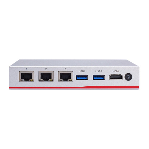
1.5.1 Front Panel.................................................................................................. 6
1.5.2 Rear Panel .................................................................................................. 8
Section 2 Hardware and Installation .................... 9
2.1 Check List............................................................................................9
2.2 Board Layout.....................................................................................10
2.3 Jumper Settings................................................................................12
2.3.1 RTC/CMOS Clear Jumper (JP1)............................................................... 13
2.3.2 TACT SW1 Function Selection Jumper (JP3/Lower Button)..................... 13
2.3.3 LAN Bypass Control Jumper (JP6/JP7/JP9)............................................. 14
2.3.4 Case open (JP8) ....................................................................................... 14
2.3.5 CRT always on (JP10) .............................................................................. 15
2.3.6 Auto Power Button Model Jumper (JP12)................................................. 15
2.4 Connectors........................................................................................16
2.4.1 ATX 2*4 pin +12V CPU Power Connector (ATX1).................................... 17
2.4.2 ATX 2*2 pin +12V Power Connector (ATX2)............................................. 17
2.4.3 Serial Port2 Connector (COM2) Co-lay CN6 ............................................ 17
2.4.4 ATX 24 pin Power Connector (CN1) ......................................................... 18
2.4.5 Nano SIM card slot (CN2)......................................................................... 18
2.4.6 M.2 E-key 2230 (CN3) .............................................................................. 19
2.4.7 M.2 B-key 2242 (CN4) .............................................................................. 20
2.4.8 Mini Card Connector (CN5)....................................................................... 21
2.4.9 LCM Connector (CN6) .............................................................................. 22
2.4.10 1X2 SFP Connector (CN7)........................................................................ 22
2.4.11 USB3.0 and console Connector (CN9)..................................................... 23
2.4.12 2*4 RJ45 Connector (CN10) ..................................................................... 23
2.4.13 Front Panel Bezel Connector (CN11)........................................................ 24
2.4.14 Digital input/output Connector (DIO1)....................................................... 25
