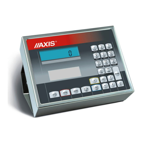
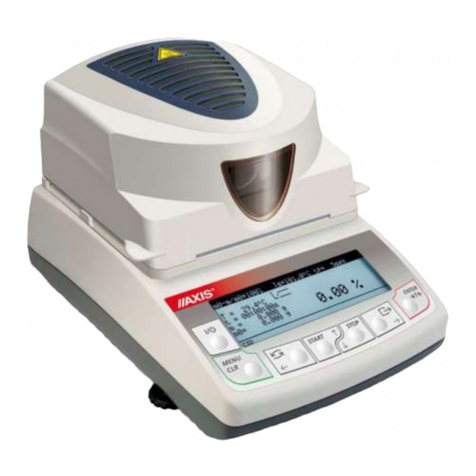
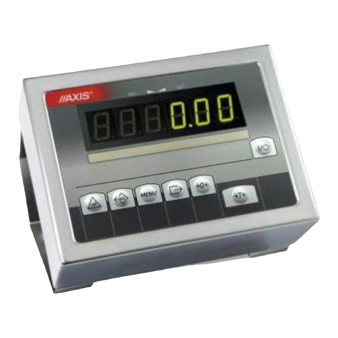
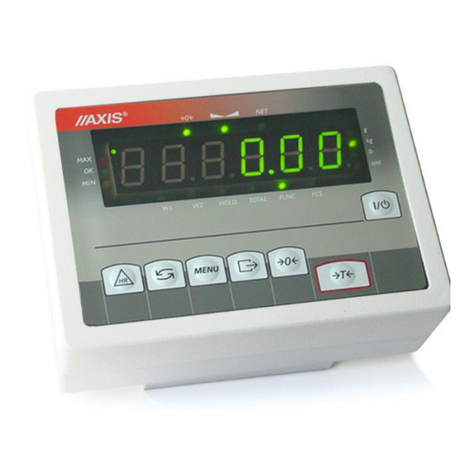
Axis ME-01 Operator's manual

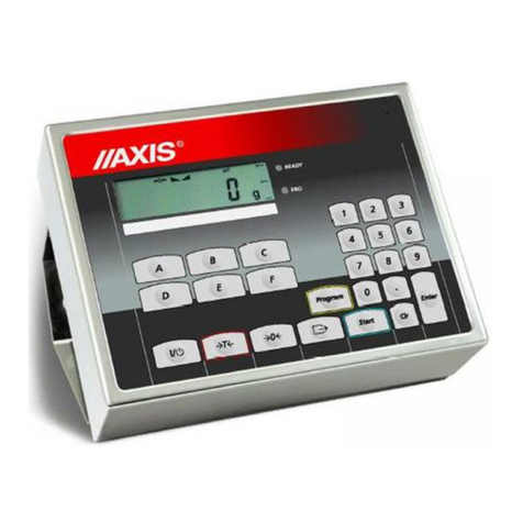
ME-01 INDICATOR
Engineering documentation
File: 2011-04 DTR-ME01A-146 bC0050 GB

2
ENGINEERING DOCEMENTATION
_____________________________________________________________________________________________________________________
Content:
1. General information .......................................................................................................................... 3
2. Completeness .................................................................................................................................. 3
3. Technical data .................................................................................................................................. 4
4. Keys and indicators .......................................................................................................................... 6
5. Security rules .................................................................................................................................... 7
6. ules proceeding with used up scales ............................................................................................. 7
7. Assembly and connecting external devices ...................................................................................... 8
7.1 Communication interfaces ..................................................................................................... 9
7.2 External key connection ....................................................................................................... 11
7.3 4-20m connection ................................................................................................................. 12
8. Scale start ...................................................................................................................................... 13
9. Operating rules ............................................................................................................................... 14
10. Scale verification ............................................................................................................................ 15
11. Adjusting the scale ......................................................................................................................... 15
12. Accumulator change (option) .......................................................................................................... 15
13. Connection with computer or printer (option) .................................................................................. 16
14. Basic scale functions ...................................................................................................................... 19
14.1 Common weighing .......................................................................................................................... 19
14.2 Weighing with tare .......................................................................................................................... 20
14.3 Balance resolution increasing ......................................................................................................... 20
15. Special functions ............................................................................................................................ 21
15.1. Customization of special functions menu (ACtIV and dEFAULt) .................................................... 23
15.2. Autozeroing function (AutotAr) ....................................................................................................... 24
15.3. Pieces counting function (PCS) ...................................................................................................... 25
15.4. Function for changing mass unit (UnIt) ........................................................................................... 26
15.5. Percent calculation functions (PErCEnt) ......................................................................................... 27
15.6. Function for summing recipe ingredients (rECIPE)......................................................................... 28
15.7. Function for calibration with external weight (CALIbr) .................................................................... 29
15.8. Label choosing function (LAbEL) .................................................................................................... 30
15.9. Function for setting serial interface parameter (Port-1 and 2) ........................................................ 31
15.10. Printout configuration (PrInt) ........................................................................................................... 32
15.11. Animal weighting function (LOC) .................................................................................................... 33
15.12. Memorizing tare function (tArE) ...................................................................................................... 34
15.13. Maximum value indication function (UP) ........................................................................................ 35
15.14. Force measuring function (nEWton) ............................................................................................... 36
15.15. Anty-disturbance filter option (FILtEr) ............................................................................................. 36
15.16. Setting backlight function (b_LIGHt) ................................................................................................. 37
15.17. Function for choosing reading unit (rESOLUt) ................................................................................. 37
15.18. Statistical calculations function (StAt) .............................................................................................. 38
15.19. Basis weight of paper counting function (PAPEr) ............................................................................ 41
15.20. Charging accumulators function (bAttErY)- option .......................................................................... 42
15.21. Automatic switching off function (Auto OFF) ................................................................................... 43
15.22. Total weight function (totAL) ............................................................................................................ 44
15.23. Date and time setting (dAtE) ........................................................................................................... 46
15.24. Function of comparing with preset threshold values (trESh) ............................................................ 47
16. Troubleshooting and maintenance ........................................................................................................ 50
ENGINEERING DOCUMENTATION
3
_____________________________________________________________________________________________________________________
1. General information
The ME-01 meter is ready subassembly, designed for single- or double-range
balances, using the extensometer force sensors.
Meter ersions:
- ME-01/A/LED – aluminium housing lacquer., LED18mm displays,
- ME-01/N/LCD – aluminium housing lacquer., LCD18mm display,
- ME-01/N/LED – stainless steel housings, LED18mm display,
- ME-01/N/LCD – stainless steel housings, LCD18mm display,
- ME-01/N/25 – stainless steel housings, LED25mm display,
As a standard ME-01 meter is a subassembly of platform and o errun balances
produced by AXIS.
Each meter has the set of special functions: automatic zeroing, pieces counting,
comparing with threshold alues, etc., which may be a ailable for the user or not –
according to the order.
In the further manual part the ME-01 meter operation is described, as the part of
complete balance.
2. Completeness
A standard set consists of:
1. ME-01 meter
2. Ferrit TN/20/10/7-3C90– 1 pcs.
3. Engineering documentation

4
ENGINEERING DOCEMENTATION
_____________________________________________________________________________________________________________________
3. Technical data
Parameter ME-01/A ME-01/N ME-01/N/25
Desti atio
to II class scales
o e, two a d three-ra ged
with verificatio u its umber ≤ 6000
a d to III class scales
o e, two a d three-ra ged
with verificatio u its umber ≤ 3000
Max verificatio u its umber
6000
I ter al resolutio
1:16 777 216
Power supply
AC:
230V
50Hz
DC: 12V
or accumulator 6V ÷ 12 V
Keyboard
Fu ctio butto s ( from 5 to 128 pcs.)
Or touch pa el (touchpad)
Display
LED, LCD (al
pha umeric or graphical)
Tra sducer supply voltage
DC: 5V or 5V keyi g (choper)
Voltage measureme t ra ge
-
10 mV
÷ 10 mV
or 0 mV
÷ 10 mV
Maximal voltage sig al for stable loadi g
+
10 mV
Mi imal voltage sig al for stable loadi g
-
10 mV or 0 mV
M
i imal allowable i put sig al correspo di g
to verificatio u it e
0,3 µV
Se sor impeda ce ra ge
40÷4000
Ω
Work temperature ra ge
- 10
°
C ÷ +40
°
C
Part of limiti g error
0,5
Se sor co ecti g
4 or 6 co ductor system
Maximal cable le gth
75 m/mm
2
Primary measureme t module fu ctio s
-
gross a d et mass i dicatio
- automatic a d semi-automatic zeroi g
- semi-automatic tare,
- co ectio with computer (RS232C, RS485,
Ether et, USB, radio)
- a alogue output
- tech ological process steeri g
- a d others
E closure type
OSA
OSN
ODN
Security level
IP40
IP65
Dime sio s
190x140x70mm
200x146x77mm
238x182x77mm
Weight
1,8kg
2,3kg
2,3kg
The metrological parameters of the balance are indicated on the rating plate.

ENGINEERING DOCUMENTATION
5
_____________________________________________________________________________________________________________________
Assembly ME-01/A ME-01/N ME-01/N/25
Assembly system
Mou ti g
2
Ф5 holes,
spaci g 59mm
2 holes
Ф5,
spaci g 160mm
2 holes
Ф5,
spaci g 203mm

6
ENGINEERING DOCEMENTATION
_____________________________________________________________________________________________________________________
4. Keys and indicators
Inscribing numerical values using menu function:
→0← - increasing inscribed digit alue,
- decimal spot,
→
T
←
- next digit,
MEN -end of inscribing.
key
I/
- Switch on / switch off(standby),
"
→
T
←
- tare (inscribing housing Wright subtracted),
" B/G - gross weight indication,
"
→
0
←
- zeroing,
" MEN - special functions menu,
"
- result printout,
" HR - higher resolution scale indications,
Indicator
→
0
←
- zeroing indication (unbiased scale),
" - weight result stabilization indication,
" NET - net mass (after using
→
T
←
key),
"
- signals acti ity one of the special functions,
Version with LCD display:
Indicator MODE - special function on indication,
" bar
indicator
- balance load indicator (0-100%).
" OFF - switching off the scale with key (standby),
" B/G - gross weight (after using B/G key),
" pcs - indication in pieces
Weight
result
metrological
data
zero
indicator
scale
buttons
stabilization
indicator
nett mass
indicator
special functions
indicator

ENGINEERING DOCUMENTATION
7
_____________________________________________________________________________________________________________________
5. Security rules
To a oid electrical shock, scale or other connected
peripheral de ices damage, it is necessary to follow the
security rules below.
• To supply the scale use power outlet with protecti e contact (not for
scales with external feeder).
• Repairs and essential scale regulations can be made only by authorized
personnel.
• To a oid fire risk use a feeder of an appropriate type (supplied with a
scale). Pay attention that supply oltage is compatible with specified
technical data.
• Do not use a scale when its co er is opened.
• Do not use a scale in explosi e conditions.
• Do not use a scale in high humidity.
• If a scale seems not to operate properly, plug it out of the mains and do
not use it until checked by authorized ser ice.
6. ules proceeding with used up scales
According to obligatory rules concerning en ironment
protection used electronic de ices should not be put in
a container with normal waste.
• After exploitation used scale should be gi en to special units authorized to
collect used electronic equipment or to the place where the de ice was
bought.

8
ENGINEERING DOCEMENTATION
_____________________________________________________________________________________________________________________
7. Assembly and connecting external devices
1. To build a scale basing on ME-01 indicator contact authorized manufacturer
ser ice point or use Installation Guide deli ered with the indicator (other
brochure).
2. The manufacturer gi es a full guaranty for ME-01 indicator only when the
indicator was mounted by AXIS Sp. z o.o. In other cases the guaranty obligation
is taken o er by the final contractor of the weighing de ice.
To comply CE marking requirements, for connecting the wires use filtering core
φ20mm.
The core should be placed within 30mm from the place of its connection.
Single strain gauge scheme inside ME-01:
When 6-wires connection of strain gauge transducers is used (REF+ and REF)
jumpers shown on the picture abo e should be soldered out from the main board
Before connecting the sensors to the indicator unplug the device from the
mains to avoid damaging the indicator.

ENGINEERING DOCUMENTATION
9
_____________________________________________________________________________________________________________________
3. Connect the external de ices cables to the meter sockets.
Diagram of common wires and shields in the platform balances:
Caution: The gal anic connection of sensors and adder housing is necessary.
7.1 Communication interfaces
In ME-01/A meter interface is placed on meter housing. In ME-01/N meter interface is placed on conductor.
All devices should be powered from the same line (phase) 230V.
1
6
2
7
3
8
4
9
5
RxD (odbiór)
TxD (nadawanie)
masa
+5V(opcja)
obudowa
RS232C
1
6
2
7
3
8
4
9
5
RS485
AA
A
WY
B
WE
B
obudowa
RxD (read)
TxD (transmit)
Ground
5V
(option)
IN
OUT
housing housing

10
ENGINEERING DOCEMENTATION
_____________________________________________________________________________________________________________________
Transmitter connection
P1-P3 (THRESHOLDS) outputs are used to connect dosing or signalling (option)
de ices. There are opto-isolators of an open collector type with 100mA / 24V
maximum load. They can be connected directly to transmitters inputs or to
MS3K/P board offered by AXIS separately or in ST 3K/P control box (3
transmitters, own power supply).
In ME-01/A connection THRESHOLD is placed on indicator’s housing. In
ME-01/N meter connection is placed on conductor.
Optional indicators outer wires ha e digital markers.
Marker
No.
Signal Wire color*
1 P1 (I threshold) Green
2 P2 (II threshold) White
3 P3 (zero) brown
10 GND (indicator ground) black or yellow
* colors might change
Diagram for direct connect a transmitter to THRESHOLD output:
* i optio without a i terface – 10 is i the place of 8
ekran
P (próg I)
P2 (próg II)
P3 (zero) masa
1
6
2
7
3
8
4
9
5
P1 (thresho d 1)
P2 (thresho d 2)
P3 (thresho d 3)
mass
screen

ENGINEERING DOCUMENTATION
11
_____________________________________________________________________________________________________________________
Outputs are adapted for direct connection RM96P transmitter of DC24V input
oltage and AC250V 8A output. Transmitter’s coil has to be secured with diode
e.g. 1N4148.
It is recommended to use MS 3K/P electronic board (3 transmitters of RM96P
type – max. load of 3A/250V) or complete ST 3K/P control box (feeder, 3
transmitters like abo e).
The way THRESHOLD outputs work is described in the separate document
(Special functions description).
7.2 External key connection
The input of external keys allows to place (make double) selected scale keys into
control box or operator’s workstation. As a standard the input is taken out with a
wire for direct connect to a control panel. ME-01 indicators can be equipped with
external key interfaces (as an option on demand).
Marker numbers and outer wires colors indicators:
Marker
No.
External keys inputs Wire color*
12
Yellow
13 MENU Brown
15
→
0
←
Green
18
→
T
←
White
20 +24V Pink
21
I
/
Blue
22 HR Red
23 B/G iolet
* colors might change
External key connecting is shown below. It is crucial to use external supply (24V)
in order to make current flow through scale transoptor input. This way of
connection pro ides gal anic separation of the scale from automatics system
which increases resistance to external interference and increases reliability.

12
ENGINEERING DOCEMENTATION
_____________________________________________________________________________________________________________________
External keys connecting:
Standard Option with interface
Scale Exter al keys Scale Exter al keys
+24V
B/G
MENU
2
3
23
20
transoptor
7.3 4-20m connection
Way of connecting analogue output 4-20mA (0-20mA, 0-10V):
Scale Exter al device
Attention: Rwe<510Ω
+24V
DC
T
MENU
0
HR
B/G
1
6
2
7
3
8
4
9
5
1
6
2
7
3
8
4
9
5
R
WE
+4-20mA
-4-20mA

ENGINEERING DOCUMENTATION
13
_____________________________________________________________________________________________________________________
8. Scale start
Connect the feeder to supply socket and the while the pan is unbiased connect
feeder’s pins to scale’s 12V socket.
This will cause following sequence of actions:
Display test.
Base electronic components test
signalized by: C-1, C-2, ...,C-4 .
Program ersion display.
Weighing readiness.
Attention:
Displaying program ersion means
positi e result of all tests.

14
ENGINEERING DOCEMENTATION
_____________________________________________________________________________________________________________________
9. Operating rules
1. Before each measurement make sure that zero indicator is displayed. If zero
indicator does not displayed or “----“ communicate appears, press →0← key
and wait until zero indication and zero indicator appears
2. The scale is equipped with tare equal to its measurement range. To tare the scale
press →T← key. In order to make mass control on pan easier and a oiding
o erflowing measurement range, scales with LCD display ha e load indicator
scaled 0÷100%.
3. Weight result should be read out while indicator is displayed (this indicator
means that the measurement is stable).
4. When there is no need to weight and only stand by mode is necessary , the scale
can be turned off using I/ key. This will switch off scale reading out system
and turns the scale to readiness state signalized by OFF indicator(scales with
LCD display). Turning on the scale is made by pressing I/ key. After autotests
the scale is ready to work with full precision.
5. Weighed sample should be placed in the centre of the platform.
6. The scale should be protected from dust, aggressi e pollens and fluids. To clean
it, it is ad ised to use a wet rag with soap and afterwards dry it.
7. The scale is equipped with accumulators (option), automatically charged while
normal work with connected power supply. Charging control take place thanks
to special function bAtterY. This function enables readout of charging state of
accumulators and also it can turn off the charging in case using batteries instead
of power supply. Discharged accumulator is displayed by BAT indicator on
LCD display, and then after about 1 hour work, the scale switches off
automatically (it switches off before the accumulator discharges underneath
oltage threshold alue).
After discharging indication appears, accumulator should be quickly connected
to external power supply. Charging is more efficient when the scale is turned off
by I/
key, charging time takes then about 10 hours.
Do not drop weighed objects on pan. To avoid this, it is
recommended to place the scale on a platform.
Do not overload the balance above 20% of maximal load (Max .
Complete discharging can damage the accumulator.

ENGINEERING DOCUMENTATION
15
_____________________________________________________________________________________________________________________
10. Scale verification
While scale exploitation, in order to check balance efficiency, before and after
measurement series it is ad ised to check weighing precision by putting on an
object with well known mass.
To check legalized scale a special actual standard of mass should be used. If the
measurement error is bigger than allowable legalized scale error, contact
authorized ser ice in order to adjust the scale.
11. Adjusting the scale
Adjusting (calibration) scale should be made if the scale precision is
not sufficient. A standard of mass should be used with Max alue taken
from scale technical data table. In case of legalized scales with
inaccessible calibration (secure seal) a contact with ser ice is
recommended.
12. Accumulator change (option)
1. Remo e screws 11
holding plate 12, remo e the
plate.
2. Take out container with
accumulators 13 and place
4 AA format accumulators.
The way of packing
accumulators into the
container is shown on the
figure on the left and is also
shown on the container.
12
11
13
RS232C
Tensometr
12V 850mA
Extensometer

16
ENGINEERING DOCEMENTATION
_____________________________________________________________________________________________________________________
13. Connection with computer or printer (option)
In order to send data to external de ices the scale is equipped with RS232C or
RS485 (option) connection.
The scale sends weighing result when initial signal form computer appears or
key of the scale is pressed.
During cooperation with printer data is sent automatically after a sample is put on
and scale indication becomes stable. Next transmission is possible after sample is
taken off. Successi e measurement number and weighing result (look at setting
serial port parameters) are sent.
In special execution the scale can be equipped with second connection. Additional
connection can be used for continuous data transmission of measurement results to
additional display.
To cooperate with scale computer must ha e a processing data from scale
programme. This types of programmes are a ailable from producer.
The description of data transmission protocol in standard mode (Long protocol
Transmission parameters: 8 bits, 1 stop bit, no parity, baud rate 4800bps,
Data exchange method:
Readout scale indication (equi alent of using key on scale):
Computer→Scale: S I CR LF (53h 49h 0Dh 0Ah) – initialization signal,
Scale→Computer: the scale sends 16 data bytes according to table:
Byte
1
-
sign „-”or space
Byte
2
-
space
Byte
3
÷
4
-
digit or space
Byte
5÷
9
-
digit, decimal point or space
Byte
10
-
digit
Byte
11
-
space
Byte
12
-
k, l, c, p, o, m, g, d or space
Byte
13
-
g, b, t, c, z, g, r, w or %
Byte
14
-
t or space
Byte
15
-
CR
Byte
16
-
LF

ENGINEERING DOCUMENTATION
17
_____________________________________________________________________________________________________________________
Note:
Network number different than zero (F..-rS / nr function) changes scale working
mode: communication with a computer is possible after logging the scale in with
02h scale_number command. To log the scale out use 03h command.
When using joint RS test programme a ailable on www.axis.pl /en/ programy
komputerowe , for example $0201 should be inscribed for scale nr 1 and then SI,
log off: $03.
Scale tare (equi alent of using →T← key on scale):
Computer→Scale: S T CR LF (53h 54h 0Dh 0Ah),
Scale→Computer: no response,
Scale zeroing (equi alent of using →0← key on scale):
Computer→Scale: S Z CR LF (53h 5Ah 0Dh 0Ah),
Scale→Computer: no response,
Turn on/off (equi alent of
I/
key):
Computer→Scale: S S CR LF (53h 53h 0Dh 0Ah),
Scale→Computer: no response,
MENU displaying (equi alent of MEN key):
Computer→Scale: S F CR LF (53h 46h 0Dh 0Ah),
Scale→Computer: no response,
Setting threshold 1 (option):
Computer→Scale: S L D1...DN CR LF (53h 4Ch D1...DN 0Dh 0Ah)
where: D1...DN –threshold alues, maximally 8 signs,
Scale→Computer: no response,
Example:
⋅ in order to set low threshold 1000g in scale B1.5 (d=0.5g) the following order
should be sent:
S L 1 0 0 0 . 0 CR LF (53h 4Ch 31h 30h 30h 30h 2Eh 30h 0Dh 0Ah),
⋅ in order to set low threshold 100kg in scale B150 (d=50g) the following order
should be sent:
S L 1 0 0 . 0 0 CR LF (53h 4Ch 31h 30h 30h 2Eh 30h 30h 0Dh 0Ah),
Setting threshold alue 2 (option):
Computer→Scale: S H D1...DN CR LF (53h 48h D1...DN 0Dh 0Ah),
where: D1...DN –threshold alue, maximally 8 signs,
Scale→Computer: no response.

18
ENGINEERING DOCEMENTATION
_____________________________________________________________________________________________________________________
Setting threshold alue 3 - zero (option):
Computer→Scale: S M D1...DN CR LF (53h 4Dh D1...DN 0Dh 0Ah),
where: D1...DN – threshold alue, maximally 8 signs,
Scale→Computer: no response.
Connecting cable WK-1 (scale – computer / 9-pin):
Sca e
Computer
Connecting cable WD-1 (scale – AXIS printer):
Sca e
Printer
Internal switches settings of AXIS printer:
SW-1 SW-2 SW-3 SW-4
SW-5
SW-6
SW-7
SW-8
on off on off off on off off

ENGINEERING DOCUMENTATION
19
_____________________________________________________________________________________________________________________
14. Basic scale functions
Meaning of graphic symbols used in further instructions:
- load on the pan
- load remo ed
- press the button during displaying
indication on the left
- forced change
- automatic change
14.1 Common weighing
The
→0←
key operates only with
unloaded pan, and zeroes the balance
indication.
The weighing result should be read
when the " " indicator is on.
2.30
T
0.00
2.31
0
2.32
12.32

20
ENGINEERING DOCEMENTATION
_____________________________________________________________________________________________________________________
14.2 Weighing with tare
The balance enables tare setting in
the whole measuring range.
.
The B/G button allows for reading
gross weight.
Caution:
Repressing the B/G button switches
the scale to the net weight display.
14.3 Balance resolution increasing
The HR button causes the momentary
result displaying (approx. 5 seconds)
with the maximum resolution,
allowed by the balance processor.
That button is especially useful in the
legalized balances with d=e reading
graduation.
The increased resolution result is the
auxiliary information, and may not be
printed or sent to the computer with
the button.
- - - - - -
2.30
0.00
40.00
42.30
T
NET
NET
2.30
2.29
2.30
Other manuals for ME-01
2
Table of contents
Other Axis Measuring Instrument manuals

Axis
Axis Companion Recorder 8CH 2TB User manual

Axis
Axis ME-01/P User manual

Axis
Axis ME-02/N/LCD User manual

Axis
Axis S1132 User manual

Axis
Axis FA Series User manual

Axis
Axis S3016 User manual

Axis
Axis Camera Station S1116 Racked Recorder User manual

Axis
Axis F9111 User manual

Axis
Axis S1148 User manual

Axis
Axis SE-03/N/LCD Operator's manual

Axis
Axis 01618-001 User manual

Axis
Axis F9114 User manual

Axis
Axis ADF Web HD67316-U-D1 User manual

Axis
Axis S3016 User manual

Axis
Axis ME-03 User manual

Axis
Axis ME-01 Installation instructions manual

Axis
Axis S10 Series User manual

Axis
Axis DV426 User manual

Axis
Axis ME-01 Operator's manual

Axis
Axis ATS60 User manual