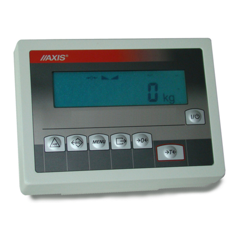
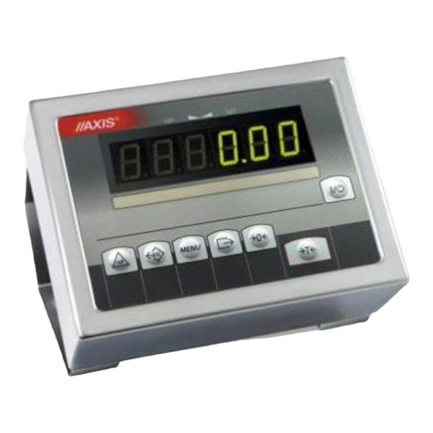
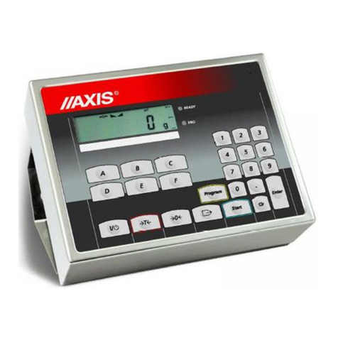
Axis ME-01 Operator's manual

ME-01 METER
Engineering documentation
FILE: 2016-04-19 DTR-ME-01-146 bC0109 GB
AXIS, 80-125 Gdańsk, ul.Kartuska 375B, www.axis.pl

2USER MANUAL ME-01
Content:
1. General information................................................................................................................................................................................. 3
2. Completeness ......................................................................................................................................................................................... 5
3. Technical data......................................................................................................................................................................................... 6
4. Assembly................................................................................................................................................................................................. 7
5. Keys and indicators................................................................................................................................................................................. 8
6. Security rules ........................................................................................................................................................................................ 10
7. Rules proceeding with used up scales.................................................................................................................................................. 10
8. Assembly and connecting external devices .......................................................................................................................................... 11
9. Meter external outputs .......................................................................................................................................................................... 13
9.1 Transmitter connection .................................................................................................................................................. 15
9.2 External key connection................................................................................................................................................. 16
9.3 4-20m connection........................................................................................................................................................... 17
9.4 Connecting a computer, printer or label printer............................................................................................................ 18
9.5 Detailed LonG protocol description............................................................................................................................... 19
9.6 Detailed EPL protocol description................................................................................................................................. 21
10. Accumulator change in aluminium meters ....................................................................................................................................................... 22
11. General rules of using scale............................................................................................................................................................................. 23
12. Balance checking and adjustment.................................................................................................................................................................... 24
13. Start-up............................................................................................................................................................................................................. 25
14. Weighing with tare............................................................................................................................................................................................ 26
15. Scale menu....................................................................................................................................................................................................... 27
16. Menu navigation rules ...................................................................................................................................................................................... 28
17. Scale setup (SEtUP)......................................................................................................................................................................................... 33
17.1 Scale calibration (CALIb)................................................................................................................................................................................ 35
17.2 Autozeroing function (AutoZEr) ..................................................................................................................................................................... 36
17.3 Weight unit selection (UnIt) ............................................................................................................................................................................ 37
17.4 Serial port parameters setting (SErIAL) ........................................................................................................................................................ 38
17.5 Printout configuration (PrInt) ........................................................................................................................................................................ 39
17.6 Setting backlight function (b_LIGHt)............................................................................................................................................................... 41
17.7 Analog out configuration (AnALoG)................................................................................................................................................................ 42
17.8 Entering reference zero value (ZErO) ............................................................................................................................................................ 43
18. Special functions description............................................................................................................................................................................ 44
18.1 Products and users database (Prod i USEr) .................................................................................................................................................. 45
18.2 Pieces counting function (PCS)..................................................................................................................................................................... 49
18.3 Percentage weighing function (PErC) ........................................................................................................................................................... 50
18.4 Label choosing function (LAbEL) ................................................................................................................................................................... 51
18.5 Weighing animals function (LOC)................................................................................................................................................................... 52
18.6 Maximum value indication function (UP)........................................................................................................................................................ 53
18.7 Force measuring function (nEWton).............................................................................................................................................................. 54
18.8 Total weight function (totAL)........................................................................................................................................................................... 55
18.9 Checkweighing function (thr).......................................................................................................................................................................... 57
18.10 Setting date and time function (dAtE)........................................................................................................................................................... 60
18.11 Radio communication channel choice function (rF CHn) ............................................................................................................................. 61
18.12 Charging accumulators function (bAttErY)- option....................................................................................................................................... 62
18.13 Automatic switching off the scale function (AutoOFF) ................................................................................................................................. 63
18.14 Statistical calculations function (StAt) .......................................................................................................................................................... 64
18.15 Paperweight calculation (PAP).................................................................................................................................................................... 67
19. Troubleshooting and maintenance ................................................................................................................................................................... 68
Declaration of Conformity CE.......................................................................................................................................................................... 69
USER MANUAL ME-01 3
1. General information
The ME-01 meter is ready subassembly, designed for single- or double-range
balances, using the extensometer force sensors.
Meter versions:
ME-01/A/18 (LED)
–housing made of
painted aluminum,
–LED18mm display,
ME-01/A/LCD
–housing made of
painted aluminum,
–LCD18mm display,

4USER MANUAL ME-01
ME-01/N/18 (LED)
–housing made of
stainless steel,
–LED18mm display,
ME-01/N/LCD
–housing made of
stainless steel,
–LCD18mm display,
ME-01/N/25 (LED)
–housing made of
stainless steel,
–wyświetlacz LED25mm,

USER MANUAL ME-01 5
As a standard ME-01 meter is a subassembly of platform and overrun balances
produced by AXIS.
Each meter has the set of special functions: automatic zeroing, pieces counting,
comparing with threshold values, etc., which may be available for the user or not –
according to the order.
In the further manual part the ME-01 meter operation is described, as the part of
complete balance.
2. Completeness
A standard set consists of:
1. ME-01 meter
2. Ferrit TN/20/10/7-3C90–1 pcs.
3. Engineering documentation

6USER MANUAL ME-01
3. Technical data
Parameter
ME-01/A
ME-01/N
ME-01/N/25
Destination
to III class scales
one and two-ranged
with verification units number n 6000
Max verification units number
6000
Internal resolution
1:16 777 216
Power supply
AC: 230V 50Hz DC: 12V or
accumulator 6V ÷ 12 V
AC: 230V 50Hz
DC: 12V
Keyboard
Function buttons ( from 5 to 128 pcs.)
Or touch panel (touchpad)
Display
LED, LCD (alphanumeric or graphical)
Transducer supply voltage
DC: 5V or 5V keying (choper)
Voltage measurement range
-10 mV ÷ 10 mV or 0 mV ÷ 10 mV
Maximal voltage signal for stable loading
+ 10 mV
Minimal voltage signal for stable loading
- 10 mV or 0 mV
Minimal allowable input signal corresponding
to verification unit e
0,3 μV
Sensor impedance range
40÷4000
Work temperature range
- 10 C ÷ +40 C
Part of limiting error
0,5
Sensor connecting
4 or 6 conductor system
Maximal cable length
75 m/mm2
Primary measurement module functions
- gross and net mass indication
- automatic and semi-automatic zeroing
- semi-automatic tare,
- connection with computer (RS232C, RS485,
Ethernet, USB, radio)
- analogue output
- technological process steering
- and others
Enclosure type
OSA
OSN
ODN
Security level
IP40
IP65
Dimensions
190x140x70mm
200x146x77mm
238x182x77mm
Weight
1,8kg
2,3kg
2,3kg
The metrological parameters of the balance are indicated on the rating plate.

USER MANUAL ME-01 7
4. Assembly
Assembly
ME-01/A
ME-01/N
ME-01/N/25
Meter grip
assembly
3 ways to mount
the meter to wall
Mounting to wall or
desktop
2 holes Ф5,
spacing 59mm
2 holes Ф5,
spacing 160mm
2 holes Ф5, spacing
203mm

8USER MANUAL ME-01
5. Keys and indicators
LCD display version:
Keys:
I/
-switch-on / switch-off (standby),
"
T
-tare, menu position confirmation, next digit (when inscribing),
"
0
-zeroing, scrolling menu, increasing digit (when inscribing),
"
-result printout, decimal point (when inscribing),
"
MENU
-menu,
"
-function switch: special function/weighing,
"
HR
-temporary high resolution indication,
Indicators:
0
-zero indicator (unloaded scale),
"
-result stabilization indicator,
"
NET
-net weight (after using Tkey),
"
MODE
-special function menu turning on indicator
"
B/G
-gross weight (after using TARE and
key)
"
AUT
-autotare function on,
"
T
-tare memory function on,
"
TOTAL, FILTER, SUM
-special functions indicators,
"
%, ct, n, g/m2, lb,mg
-unit indicators,
"
pcs
-pieces counting indicator,
"
n
-measurements quantity indicator (total function),
"
OFF
-scale turned off (standby)
"
MIN
-weighing result under threshold I (thr function),
"
OK
-weighing result between threshold I and II,
"
MAX
-weighing result above threshold II,
BAT
-battery discharge indicator,
, O
-ACtIV function indicator,
bar
indicator
-scale load indicator (0-100%)
0
kg
scale
keys
weighing
result
bar
indicator
metrological
data
zero
indicatorstabilization
indicator net weight
indicator
Max= d=

USER MANUAL ME-01 9
LED display version:
klawisz
I/
-switch-on / switch-off (standby),
"
T
-tare, menu position confirmation, next digit (when inscribing),
"
0
-zeroing, scrolling menu, increasing digit (when inscribing),
"
-result printout, decimal point (when inscribing),
"
MENU
-menu,
"
-function switch: special function/weighing,
"
HR
-temporary high resolution indication,
wskaźnik
0
-zero indicator (unloaded scale),
"
-result stabilization indicator,
"
NET
-net weight (after using Tkey),
"
W1
-first range on in two-range scale,
"
W2
-second range on in two-range scale,
"
HOLD
-indication „locked” (concerns LOC and UP functions),
"
FUNC
-special function turned on,
"
PCS
-pieces counting,
"
g, kg, lb, unit
-weight unit (g-gram, kg-kilogram, lb-pound, unit –other),
"
MIN
-weighing result under threshold I (thr function),
"
OK
-weighing result between threshold I and II,
"
MAX
-weighing result above threshold II,
During inscribing numerical values needed during using special functions keys have special functions.
scale
keys
weight
result metrological
data
zero
indicatorstabilization
indicator net weight
indicator
Max= d=

10 USER MANUAL ME-01
6. Security rules
To avoid electrical shock, scale or other connected
peripheral devices damage, it is necessary to follow the
security rules below.
To supply the scale use power outlet with protective contact (not for
scales with external feeder).
Repairs and essential scale regulations can be made only by authorized
personnel.
To avoid fire risk use a feeder of an appropriate type (supplied with a
scale). Pay attention that supply voltage is compatible with specified
technical data.
Do not use a scale when its cover is opened.
Do not use a scale in explosive conditions.
Do not use a scale in high humidity.
If a scale seems not to operate properly, plug it out of the mains and do
not use it until checked by authorized service.
7. Rules proceeding with used up scales
According to obligatory rules concerning environment
protection used electronic devices should not be put in
a container with normal waste.
After exploitation used scale should be given to special units authorized to
collect used electronic equipment or to the place where the device was
bought.

USER MANUAL ME-01 11
8. Assembly and connecting external devices
1. To build a scale basing on ME-01 indicator contact authorized manufacturer
service point or use Installation Guide delivered with the indicator (other
brochure).
2. The manufacturer gives a full guaranty for ME-01 indicator only when the
indicator was mounted by AXIS Sp. z o.o. In other cases the guaranty obligation
is taken over by the final contractor of the weighing device.
To comply CE marking requirements, for connecting the wires use filtering core
20mm.
The core should be placed within 30mm from the place of its connection.
Single strain gauge scheme inside ME-01:
When 6-wires connection of strain gauge transducers is used (REF+ and REF)
jumpers shown on the picture above should be soldered out from the main board
(load cell wires are connected EXC+, EXC-, IN+,IN- and additionally REF+ and
REF-).
Commonly used wire colors:
EXC+ red
Before connecting the sensors to the indicator unplug the device from the
mains to avoid damaging the indicator.

12 USER MANUAL ME-01
EXC- black
IN+ green
IN- white
REF+ brown
REF- yellow
3. Connect the external devices cables to the meter sockets.
Diagram of common wires and shields in the platform balances:
Caution: The galvanic connection of sensors and adder housing is necessary.
All devices should be powered from the same line (phase) 230V.

USER MANUAL ME-01 13
9. Meter external outputs
ME-01 meter in aluminium housing:
RS232C WY Extensometer
12V 1,2A
RxD (receive)
TxD (transmission)
mass
housing
RS232C
1
2
3
4
5
6
7
8
9
P2 (threshold 2)
P1 (threshold I)
P3 (threshold )
ground
housing
WY (option)
1
2
3
4
5
6
7
8
9
Feeder

14 USER MANUAL ME-01
ME-01 meter in stainless steel housing:
Separate ground connection (scales in stainless steel version) must be connected using additional
conductor.
Extensometers are connected permanently.
RS232C Extensometer
Power unit 12V
Feeder
USB
Ground
RxD (receive)
ground
housing
RS232C
1234 5
67 8 9

USER MANUAL ME-01 15
9.1 Transmitter connection
P1-P3 (THRESHOLDS) outputs are used to connect dosing or signalling (option)
devices. There are opto-isolators of an open collector type with 100mA / 24V
maximum load. They can be connected directly to transmitters inputs or to
MS3K/P board offered by AXIS separately or in ST 3K/P control box (3
transmitters, own power supply).
In ME-01/A connection THRESHOLD is placed on indicator’s housing. In
ME-01/N meter connection is placed on conductor.
Optional indicators outer wires have digital markers.
Marker
No.
Signal
Wire color*
1
P1 (I threshold)
Green
2
P2 (II threshold)
White
3
P3 (zero)
brown
10
GND (indicator ground)
black or yellow
* colors might change
Diagram for direct connect a transmitter to THRESHOLD output:
* in option without an interface –10 is in the place of 8
ekran
P1 (próg I)
P2 (próg II)
P3 (zero) masa
1
6
2
7
3
8
4
9
5
P1 (threshold 1)
P2 (threshold 2)
P3 (threshold 3)
mass
screen

16 USER MANUAL ME-01
Outputs are adapted for direct connection RM96P transmitter of DC24V input
voltage and AC250V 8A output. Transmitter’s coil has to be secured with diode
e.g. 1N4148.
It is recommended to use MS 3K/P electronic board (3 transmitters of RM96P
type –max. load of 3A/250V) or complete ST 3K/P control box (feeder, 3
transmitters like above).
The way THRESHOLD outputs work is described in the separate document
(Special functions description).
9.2 External key connection
The input of external keys allows to place (make double) selected scale keys into
control box or operator’s workstation. As a standard the input is taken out with a
wire for direct connect to a control panel. ME-01 indicators can be equipped with
external key interfaces (as an option on demand).
Marker numbers and outer wires colors indicators:
Marker
No.
External keys inputs
Wire color*
12
Yellow
13
MENU
Brown
15
0
Green
18
T
White
20
+24V
Pink
21
I/
Blue
22
HR
Red
23
B/G
violet
* colors might change
External key connecting is shown below. It is crucial to use external supply (24V)
in order to make current flow through scale transoptor input. This way of
connection provides galvanic separation of the scale from automatics system
which increases resistance to external interference and increases reliability.

USER MANUAL ME-01 17
External keys connecting:
Standard Option with interface
Scale External keys Scale External keys
+24V
B/G
MENU
12
13
23
20
transoptor
9.3 4-20m connection
Way of connecting analogue output 4-20mA (0-20mA, 0-10V):
Scale External device
Attention: Rwe<510Ω
+24V
DC
T
MENU
0
HR
B/G
1
6
2
7
3
8
4
9
5
1
6
2
7
3
8
4
9
5
RWE
+4-20mA
-4-20mA

18 USER MANUAL ME-01
9.4 Connecting a computer, printer or label printer
The scale is equipped with RS232C, which can be used to connect external devices such as computer or
a printer.
When cooperating with computer, the scale sends weighing result after initialize signal from computer or
after pressing key on the scale.
When cooperating with a printer data is send automatically after result stabilisation, but next transmission is
possible after removing previously weighted sample.
When cooperating with label printer after pressing key, the scale sends instructions set for the label
printer. Label number 0001, hour, data (if the clock is installed and on) and nett weight. During transmission
LabEL communicate is displayed.
The way of sending data and transmission parameters is set using SErIAL special function.
Set of send data is set using special function PrInt.
The following data can be send:
-Header (scale type, Max, d, e, serial number),
-Operator identification number,
-Successive printout number (measurement),
-Identification number or product bar code,
-Number of pcs (PCS function only),
-Single detail mass (PCS function only),
-Nett weight,
-Tare (package mass),
-Gross weight,
-Total mass (Total function only).
If the scale is equipped with two serial joints Print function is set independently for both interfaces.
Computer must have a special program for cooperation with data from a scale.
Dedicated programs are also offered by AXIS.
Except RS232C joint, the scale can be equipped with USB or Wi-Fi interface.
Needed controllers and instruction can be found on a CD supplied with Axis scales.

USER MANUAL ME-01 19
9.5 Detailed LonG protocol description
Standard communication parameters: 8 bits, 1 stop bit, no parity, baud rate 9600bps,
After using key, measurement data is send together with text description (NET, TARE, GROSS) –all
set by using Print option. If Print isn’t set then only scale indication is send (as below).
Data exchange (communication):
Readout of scale indication
ComputerScale: S I CR LF (53h 49h 0Dh 0Ah),
ScaleComputer: scale response according to description below (16 bytes):
Byte
1
-
sign „-” or space
Byte
2
-
space
Byte
34
-
digit or space
Byte
5÷9
-
digit, decimal point or space
Byte
10
-
digit
Byte
11
-
space
Byte
12
-
k, l, c, p or space
Byte
13
-
g, b, t, c or %
Byte
14
-
space
Byte
15
-
CR
Byte
16
-
LF
Attention:
Network number different than zero (SErIAL / nr function) changes scale working mode: communication
with a computer is possible after logging the scale in with 02h scale number command. To log the scale out
use 03h command.
For example: Using a program to test RS232 interface ( program is available in www.axis.pl / programy
komputerowe ) for scale number 1 please write: $0201 to log in, then SI, and write: $03 to close
communication.
Asking about scale presence in system (testing scale connection with computer):
ComputerScale: S J CR LF (53h 4Ah 0Dh 0Ah),
ScaleComputer: M J CR LF (4Dh 4Ah 0Dh 0Ah),
Displaying a inscription on scale’s display (text communicate from computer):
ComputerScale: S N n n X X X X X X CR LF, nn-displaying time in seconds; XXXXXX-6 signs to
display
ScaleComputer: M N CR LF (4Dh 4Eh 0Dh 0Ah),
Scale tarring (calling
T
key press) :
ComputerScale: S T CR LF (53h 54h 0Dh 0Ah),
ScaleComputer: without response,
Scale zeroing (calling
0
key press):
ComputerScale: S Z CR LF (53h 5Ah 0Dh 0Ah),
Scale Computer: without response,
Scale turning on / off (calling I/ key press):
ComputerScale: S S CR LF (53h 53h 0Dh 0Ah),
Scale Computer: without response,

20 USER MANUAL ME-01
Entering to special function menu (calling MENU key press):
ComputerScale: S F CR LF (53h 46h 0Dh 0Ah),
Scale Computer: without response,
Setting threshold 1 value (option):
ComputerScale: S L D1...DN CR LF (53h 4Ch D1...DN 0Dh 0Ah)
D1...DN –threshold value, maximum 8 characters („-” –negative value, digits, dot –decimal
separator), number of digits after dot should be the same as on scale display,
Scale Computer: without response,
Example:
in order to set low threshold 1000g in scale B1.5 (d=0.5g) the following order should be sent:
S L 1 0 0 0 . 0 CR LF (53h 4Ch 31h 30h 30h 30h 2Eh 30h 0Dh 0Ah),
in order to set low threshold 100kg in scale B150 (d=50g) the following order should be sent:
S L 1 0 0 . 0 0 CR LF (53h 4Ch 31h 30h 30h 2Eh 30h 30h 0Dh 0Ah),),
Setting threshold 2 value (option):
ComputerScale: S H D1...DN CR LF (53h 48h D1...DN 0Dh 0Ah),
D1...DN –threshold value, maximum 8 characters
Scale Computer: without response.
Setting threshold 3 value (option):
KomputerWaga: SMD1...DN CR LF (53h 4Dh D1...DN 0Dh 0Ah),
gdzie: D1...DN –threshold value, maximum 8 characters
WagaKomputer: without response.
Connecting cable WK-1 (scale –computer / 9-pin interface):
Connection cable WD-1 (connects scale with AXIS printer):
Setting of internal switches of AXIS printer:
SW-1
SW-2
SW-3
SW-4
SW-5
SW-6
SW-7
SW-8
on
off
on
off
off
on
off
off
SCALE
KAFKA PRINTER
SCALE
COMPUTER
Other manuals for ME-01
2
This manual suits for next models
5
Table of contents
Other Axis Measuring Instrument manuals

Axis
Axis AGS200/T250 User manual

Axis
Axis S1132 User manual

Axis
Axis ME-01 Operator's manual

Axis
Axis 01618-001 User manual

Axis
Axis ADF Web HD67316-U-D1 User manual

Axis
Axis S3016 User manual

Axis
Axis SE-01 Operator's manual

Axis
Axis Companion Recorder User manual

Axis
Axis ME-01/P User manual

Axis
Axis ME-02/N/LCD User manual
Popular Measuring Instrument manuals by other brands

Qiagen
Qiagen QIAxcel Connect quick start guide

AKO
AKO AKO-59811 instructions

PCB Piezotronics
PCB Piezotronics WJ356B11/NC Installation and operating manual

Tempo Communications
Tempo Communications CableScout CS90B user manual

ModMAG
ModMAG M-Series M3000 user manual

VOLTCRAFT
VOLTCRAFT AM-72X72 operating instructions