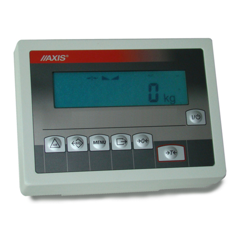
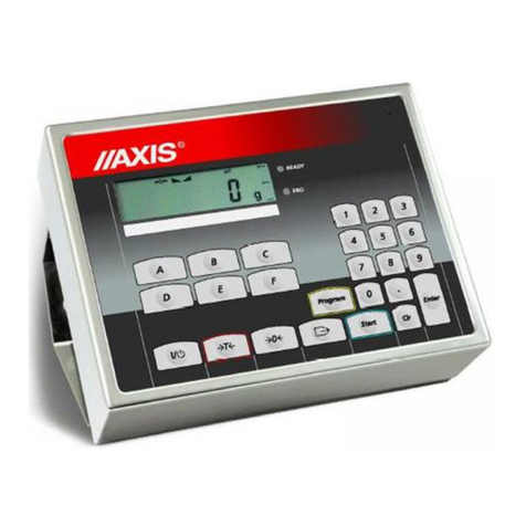
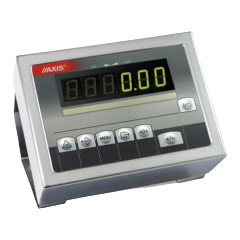
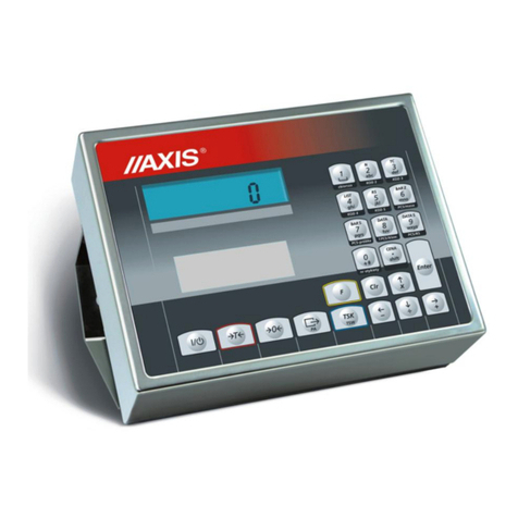
Axis ME-01 Installation instructions manual

MOUNTING GUIDE
ME-01 indicator
File: 2014-10-01 ME-01_mounting bE_bC0100 GB

MOUNTING GUIDE
2
Content:
1. Introduction ________________________________________________________________3
2. Connecting load cells _________________________________________________________4
3. General description of scale’s firmware __________________________________________8
3.1 Keys and meter indicators _________________________________________________________11
3.2 Scale programming sequence_______________________________________________________12
3.3 General rules during scale programming_____________________________________________12
4. Service menu description _____________________________________________________13
4.1 Options connected with work mode (ModE) __________________________________________13
4.2 Special functions (On_F) __________________________________________________________14
4.3 Functions connected with scale adjusting (CALIb) _____________________________________14
4.4 Working mode changing standard / service (StAn)_____________________________________14
5. Basic programming operations ________________________________________________14
5.1 Entering a service catalogue –scale decoding (should be necessarily done first) _______________________ 15
5.2 Scale monitoring ________________________________________________________________________ 15
5.3 Scale type selection ______________________________________________________________________ 15
5.4 Sensitivity calibration ____________________________________________________________________ 18
5.4.1. Calibration with incomplete (part) load ____________________________________________________ 18
5.5 Enter first zero value (reference zero) ________________________________________________________ 19
5.6 Temperature compensation ________________________________________________________________ 19
5.7 Linearity calibration _____________________________________________________________________ 20
5.8 RS232 interface installation _______________________________________________________________ 21
5.9 Digital filters setting (connected with indication dynamics) _______________________________________ 21
5.9.1 Setting initial filter AvEr_A and proper filter AvEr_b__________________________________________ 21
5.9.1.1 Proper filter options rAt_A, rAt _b ___________________________________________________________ 21
5.9.2 rAt_Stb option __________________________________________________________________________ 22
5.9.3 dEL_A, dEL_b, dEL_Stb option ______________________________________________________________ 22
5.9.4 MEdIA option___________________________________________________________________________ 22
5.10 User function choice ____________________________________________________________________ 22
5.11 Out from service catalog- scale coding (crucial after repairing the scale!!) __________________________ 22
6. Special functions ___________________________________________________________ 23
7. Mechanics description _______________________________________________________ 24
7.1 Load cell mounting _______________________________________________________________24
7.2 Limiters adjusting ________________________________________________________________25
7.3 Disassembly and assembly of scale housing___________________________________________26
7.4 Centricity checking and regulation __________________________________________________27
8. Common scale failures_______________________________________________________28
8.1 Messages about errors and faults ___________________________________________________28
8.2 Most frequent faults ______________________________________________________________29

MOUNTING GUIDE
3
1. Introduction
This manual describes AXIS meters:
-ME-01/A/LED
-ME-01/A/LCD
-ME-01/N/LED
-ME-01/N/LCD
-ME-01/N/25 (LED)
- ME-01/P/LCD
- ME-01/P/25
with bE0100 (LED version) and bC0199 (LCD version) firmware or later.
Detailed description of meters and scales based on the meters way of working can be found in user manual of specific
type of meter. User manuals can be used by scale’s operators.
Mounting manual consists:
-Load cells mounting recommendations
-Supply and grounding way of connection
-Sensor parameters selection to built specific scale type
-Scale calibration
-Service menu
-Setup option –user menu
-Mechanical mounting recommendations
-Securing the sensor
-Error communicates

MOUNTING GUIDE
4
2. Connecting load cells
2.1 Sensor selection
General requirements for tensometric sensors (load cells):
Max quantity of sensors
8 pcs
Total impedance (all sensors)
40÷4000
Connecting sensors
4 or 6 wire system
Maximal cable lenght to cable diameter
75 m/mm2
Sensor supply
5V (choper)
Select sensors according to rules below:
1. When 1 sensor is used scale measurement range (Max) mustn’t exceed 40-80% of sensor’s range (Emax)
2. When many sensors are used scale measurement range (Max) mustn’t exceed 15-45% sum of all sensors
range (n*Emax). If uneven weight load is possible provide at least 25% of safety margin of each sensor.
2.2 Connecting sensors to main board
To comply CE marking requirements, for connecting the wires use filtering core 20mm.
The core should be placed within 30mm from the place of its connection.
Commonly used wire colors:
EXC+ red
EXC- black
IN+ green
IN- white
REF+ brown
REF- yellow
Before connecting the sensors to the indicator unplug the device from the mains to avoid damaging
the indicator.

MOUNTING GUIDE
5
ME-01/A … 4 wire connection scheme:
When 6-wires connection of strain gauge transducers is used (REF+ and REF) cramps shown on the picture above
should be soldered out from the main board (load cell wires are connected EXC+, EXC-, IN+,IN- and additionally
REF+ and REF-).

MOUNTING GUIDE
6
2.3 Sensors check
To check if tensometric sensors (load cells) are ok use Calib/Zero option. In zero option scale displays result in
internal resolution (results directly from A/D converter).
Input voltage range: 0Umax
A/D result range: 0 ~160 000 internal division (on chart 160 000 is 100% of A/D range)
Default Umax value is 10mV and can be changed to 20, 40 or 80mV. Option CALIb / AdC / RanGE is used for that.
If negative input signal values are needed, turn on option CALIb / AdC / bIPOL.
Inpit voltage values: –Umax +Umax
Results range: 0 ~160 000 internal division (as above)
A/D
U
U
0
10% (16 000)
80% (128 000)
100% (160 000)
WE
max
Work
range
empty pan
Max load
A/D
U
U-U 0
10% (16 000)
80% (128 000)
100% (160 000)
WE
maxmax
working
range
empty pan
Max load

MOUNTING GUIDE
7
2.4 GND connection
Connection between GND of different scale parts is crucial for disturbance low level on measurement input and
moreover lack of the connection can cause permanent damage to meter’s internal units, where CMOS transistors
work –sensitive to surges.
Caution: The galvanic connection of sensors and adder housing is necessary.
To make GND connection use sensor’s factory GND connection or one of the wires that extend factory connection or
additional wire. Stainless steel housing meters have special external GND clip. The connection should be made with
thick wire. As a model look at AXIS constructions.
2.5 Connecting external devices
All devices connected with scale must be supplied from the same line (phase) 230V.

MOUNTING GUIDE
8
3. General description of scale’s firmware
The firmware consists part for USER (normal weighing, special functions) and for SERVICE (service menu
functions).
Service menu diagram:
ModE SCALE
SErIAL
AvErAG
OPtionS
bA-... ( -2,-3,-3500,-400,-50,-6,-10,-15, out)
bAY-... ( -3,-6,-12,-30,-60,-120, out)
SEt
other
out
Port-1
Port-2
out
MEdIA
AvEr_A
AvEr_b
rAt_A
rAt_B
rAt_St
dEL_A
dEL_b
dEL_St
out
AutoTA
ZEroin
unLOAD
dELtA
LAtch
FASt_t
ZEro-S
out
(Scale type)
tYP LEG
rANGE
(Serial ports parameters)
LEG OFF
LEG on
out
nLEGAL
LEGAL
out
SEt-H
LAST
out
GrAM
HGrAM
out 1-rAnG
2-rAnG
out
1-rAnG
2-rAnG
out
MAX
...
out SEt-d
...
out YES
nO
bAud
bItS
ParItY
SEnd
nr
Prot
WI-FI
out
(as above)
-
- transmission speed (bps)
- bits quantity (7 or 8)
- parity control
- transmission mode
- scale number in network
- transmission protocol
- Wi-Fi module on/off
- number of results taken to digital filter (median)
- number of results taken to initial averaging (filter A)
- allowed results difference for A filter
-
-
- automatic holding zero value after start
- turning on key and indication
- start zero error signalization
- result creeping stop
- latching result (not used)
- fast taring
- zeroing off after start
- out
other options
- signalling H threshold (Max+9e)
- hiding last digit of indication
- number of results taken to main averaging (filter B)
allowed results difference for B filter
allowed results difference for stability
- A filter delay
- B filter delay
- stability delay
- out
BE_BC0069 bE0069 (bC0069) service menu Ark. 1/2Rys.
-
-
- set scales (special)
- not legalised
- legalised
- g unit indication
- kg unit indication
- 1-range scale
- 2-range scale
- Max range (inscribing)
- actual Max value
- actual d value
- confirmation
- exit without changes
BA series scales
BA/Y series scales
- (calibration available)
- (calibration not available )
- out
-
-
- out
- d plot (inscribing)
not legalised scale
legalised scale
1-range scale
double-range scale
, d=e
0

MOUNTING GUIDE
9
on_F
CALIb
StAn
CodE
out
ZEro
LINEAr
COMP.
ErASE
CAL dd
CAL Pt
CELL
AdC
SEr no
out
StAn-0
StAn-1
Prn_EE
Prn_CM
Prn_LI
out
CodE-0
CodE-1
out
- initial load value inscribing (starting zero)
- out
- zero value inscribing
- linearization of scale’s characteristic
- temperature compensation
- data memory erasing (EEPROM)
- calibration correction by a certain quantity of plots
- calibration with incomplete load
- calibration by inscribing load cell parameters (Max and sensitivity)
- readout directly from A/C
- inscribing scale serial (factory) number
- scale in service mode
- scale in standard mode
- EPROM printout
- cache memory printout
- linearity parameters printout
- out
- scale uncode (acces to service menu)
- code scale
- out
- out
ZEro
out
Ark. 2/2Rys. BE_BC0069 bE0069(bC0069) service menu
Prt-rF
out
rF-868
rF-915
rF-433
out
- band 868MHz turned on
- band 915MHz turned on
- out
- band 433MHz turned on

MOUNTING GUIDE
10
In further chapters of the manual, mainly service options are described. User options are described in user manual.
Working mode settings and storing parameters can be performed by selection (activation) of proper functions in
service menu. The settings are stored in internal memory (EEPROM). The process will be called scale programming
(setting).
In order to get access to service menu enter 6-digit code:
781213
Secure code should be inserted once more in order to secure the scale.
In legalized scales access to calibration and programming is blocked (Pr-off communicate) additionally by jumper
inside the meter (LCD version):
Access to calibration jumper. On the picture access is open (Pr-on communicate).

MOUNTING GUIDE
11
3.1 Keys and meter indicators
Version with LED display:
key
I/
-ON/OFF switch (standby),
key
T
-tare set (entering package weight, subtracted from weighed mass),
key
0
-zeroing,
key
MENU
-access to special functions menu,
key
-result print (data transmission),
key
HR
-high resolution,
key
-switch: special function / weighing
indicator
0
-zero indicator,
indicator
-signals weighing result stabilization,
indicator
NET
-net weight indicator (indication with subtracted tare),
indicator
W1
-two-range scale first range on
indicator
W2
-two-range scale second range on
indicator
HOLD
-hold indication (LOC and UP function)
indicator
FUNC
-special function on,
indicator
PCS
-indications in pieces,
indicator
g, kg,
lb, unit
-mass indications in chosen units,
indicator
MAX
-mass indications exceeded the II threshold,
indicator
OK
-mass indications between I and II threshold,
indicator
MIN
-mass indications under I threshold.
weighing
result
metrological
data
zero
indicator
MAX
W1
0 NET
W2 HOLD TOTAL FUNC PCS
g
kg
lb
unit
MIN
scale
keys
stabilization
indicator
netto
mass
indicator
Max= d=

MOUNTING GUIDE
12
3.2 Scale programming sequence
After mechanical and electronic assembly to program the scale follow the sequence below. Information necessary for
mechanical and electronic installation is described in chapter 2 and 3 and in DTR manual (delivered with the scale).
1. Enter the Service Menu
2. Set scale type
3. Set working mode (if necessary)
4. Register primary zero value
5. Sensitivity calibration
6. Check temperature sensor (monitoring) and proceed with the temperature compensation (if necessary)
7. Check linearity characteristics and proceed with the linearity correction if necessary
8. Check balance sensitivity and enter sensitivity correction if necessary
9. In case any additional facilities enable necessary user functions
10. Code the moisture analyser.
Some of the actions can be bypassed, if we state that the scale doesn’t need them. Particularly temperaturę
compensation can be omitted after repairing feeder, display or other main board part.
3.3 General rules during scale programming
MENU key recalls option set. The abbreviations of option names appear on the display successively.
To choose (accept) needed option press Tkey while abbreviation of desired option is displayed,
some options need to choose 0or 1; choose 0to resign and return to the previous step or 1to activate the option,
if ”o” sign (or a point in the upper left corner in LED version) lights by the option name, the displayed option is
enabled,
Due to failures that sometimes apppear (in production or service process) if a "-CODE-" (the scale is not coded)
communicate appears after each scale switching on, user can bypass the communicate by using MENU key,
After each turning on the scale autotests start (C-1, ..., C-4).

MOUNTING GUIDE
13
4. Service menu description
Service menu (not available for user) consists options and functions set that decide about scale working mode.
Service menu consists of following option catalogs:
ModE –options connected with scale working mode
On-F –user special functions
CALIb –functions connected with scale adjusting
StAn –user mode selection (standard) or service mode, EPROM content printout
CodE –service menu access coding
4.1 Options connected with work mode (ModE)
This options decide about principal metrology parameters of scale:
SCALE –choose of range and type of scale
SErIAL (Port-1 and Port-2) –setting first and second serial port:
-bAUd –transmission speed setting (bps),
-bitS –number of bits (in byte),
-Parity –parity control,
-Send –transmission modes (after pressing ):
OFF - transmission key off,
StAb –transmission after stabilization,
No_StAb –transmission without stabilization,
Auto –automatic transmission after putting on load,
Cont. –continuous transmission,
rEMOV –transmission after taking off load.
-nr –scale number in network,
-Prot –transmission protocol:
Long –Scale standard protocol,
ELTROn –label print protocol,
PEN-01 –pendrive protocol.
- WI-FI –Wi-Fi module turning on
AvErAG –dynamic parameters of scale (averaging options)
OPtIon –taring options, zeroing options, control of starting zero, measurement filters.

MOUNTING GUIDE
14
rF –options for radio communication
4.2 Special functions (On_F)
ZErO option is used to inscribe starting zero value (primary zero). Using this function is essential when additional
construction elements are put on the pan e.g. container. Without inscribing correct value of start load „unLOAd”
communicate appears.
4.3 Functions connected with scale adjusting (CALIb)
Calibration parameters menu:
ZEro –set a reference zero value (after start scale compares indications with this value)
LInEAr –linearity of scale characteristics (load up)
COPMPt –temperature compensation (not used in standard)
ErASE –erase entries: CAL-calibration, LIn-linearity, ALL- all
CAL dd –change scale sensitivity with selected division value (+/- divisions)
CAL Pt –calibration with not maximal load
CELL –calibration by inscribing load cel parameters (Max and sensivity)
AdC –setting AdC transducer (not used in standard situatuin)
SEr no –inscribing serial (factory) number.
4.4 Working mode changing standard / service (StAn)
This menu allow to set service or standard mode and print reports:
StAn-0 –service mode (many unnecessary functions during repair/setting are deactivated eg. special functions)
Stan-1–standard mode (user mode)
Prn-EE –printout all contents of EEPROM
Prn-CM –printout of cache memory
Prn- LIn–printout of linearity
5. Basic programming operations
The first operation should be entering the service catalogue.
Only sensitivity calibration is possible without entering service catalog.
During reparations it is advised to follow programming sequence described in this chapter.

MOUNTING GUIDE
15
5.1 Entering a service catalogue –scale decoding (should be necessarily done first)
press MENU key.
Choose SEtuP and SErVICE
Enter 6 digit access code by using keys:
- 0- changes value of displayed digit.
- T- shifts digit to left,
press MENU key after entering code number,
NOTE:
When scale is decoded entering service catalog doesn’t require access code.
enter CodE-0 by pressing Tkey,
select StAn and StAn -0 option,
perform scheduled activities in service catalog or press MENU key to switch to weighting operation.
5.2 Scale monitoring
press MENU key.
choose SEtuP and SErVICE by pressing Tkey,
select CALIb and ZEro option,
read direct A/D transducer indication; there should be:
Scale type
A/D indication
A/C division difference beetwen
Max and 0 load
0 load
Max load
...
from 100 divisions
Up to 160 000
divisions
At least 30 000 divisions
In case of clearly unstable or different values, check limit switches setting, supply voltages, reference A/D
transducer or exchange strain gauge.
press MENU key to exit from function.
5.3 Scale type selection
Scale type selection has crucial role in programming scale. Weighing range and readout unit is automatically set
when the scale type is selected. Moreover other factory options are set and initial calibration (very inaccurate but
ensures the scale cooperates with typical load cell).
Actions sequence:
press MENU key,
choose SEtuP and SErVICE by pressing Tkey,
781213

MOUNTING GUIDE
16
select ModE and SCALE option,
select proper scale type:
- initial selection –according to letter type –ex. for B2D scale (=BA2D) choose „bA-”
- further selection –according to successive digits –ex. for B2D scale (=BA2D) choose „2”
- final selection –according to successive digits –ex. for B2D scale (=BA2D) choose „2d”
Available scale types:
Menu
Initial
selection
Further
selection
Final
selection
Metrological type of
scale
Max
d
e
trYb / SCALE
-bA...
- 2...
- 2d
scale BA2D
2000g
1g
1g
- 2
- ” - BA2
2000,0g
0,1g
1g
B 200
- ” - BA200
200,00kg
0,01kg
0,1kg
B 200L
- ” - BA200L
200,00kg
0,1kg
0,1kg
B 2000
- ” - 4BA2000
2000kg
1kg
1kg
- 3...
- 0,3d
- “ -BA0.3D
300g
0,1g
0,1g
- 0,3
- “ -BA0.3
300g
0,01g
0,01g
- 3d
- ” - BA3D
3000g
1g
1g
- 3
- ” - BA3
3000g
0,1g
1g
- 30
- ” - BA30
30,00kg
0,01kg
0,01kg
- 300
- ” - BA300
300kg
0,1kg
0,1kg
- 3000
- ” - 4AB3000
3000kg
1kg
1kg
- 3500
- ” - BA3500
3500,0kg
0,1kg
1kg
- 400
- ” - 4BA400
400,0kg
0,2kg
0,2kg
- 50
- ” - BA50P
50,00kg
0,02kg
0,02kg
- 6...
- 0.6d
- ” - BA0.6D
600,0g
0,2g
0,2g
- 0.6
- ” - BA0.6
600,00g
0,02g
0,2g
- 6d
- ” - BA6D
6000g
2g
2g
- 6
- ” - BA6
6000g
0,2g
2g
- 60
- ” - BA60
60,00kg
0,02kg
0,02kg
- 600
- ” - 4BA600
600kg
0,2kg
0,2kg
- 6000
- ” - 4BA6000
6000kg
2kg
2kg
- 10...
- 10
- ” - BA10
10 000g
1g
5g
- 1000
- ” - 4BA1000
1000,0kg
0,5kg
0,5kg
- 15...
- 1.5d
- ” - BA1.5D
1500g
5g
5g
- 1.5
- ” - BA1.5
1500,00g
0,05g
0,5g
- 15d
- ” - BA15D
15000g
5g
5g
- 15
- ” - BA15
15000g
1g
5g
B 150
- ” - BA150
150,00kg
0,05kg
0,05kg
B 1500
- ” - 4BA1500
1500,0kg
0,5kg
0,5kg
-2.5
-bAY...
- 3
- ” - BA6Y
3000g
0,5g
0,5g
- 6
- ” - BA6Y
6000g
1g
1g
- 12
- ” - BA12Y
12000g
2g
2g
- 25
- 30
- ” - BA30Y
30,00kg
0,005kg
0,005kg
- 60
- ” - B60Y
60,00kg
0,01kg
0,01kg
- 120
- ” - BA120Y
120,00g
0,02kg
0,02kg

MOUNTING GUIDE
17
choose (activate) legalized scale type (if needed) - tYP_LEG
Not legal scale (nLEGAL)
-displaying last digit
-0key turned off
During normal work (switch in standard position ) and during service work (switch in service position) in calibration
option all sub-options are available. Access to calibration is possible through SEtuP (User menu) or through service
menu.
Legalized scale (LEGAL)
-Displaying last digit,
-AutotAr option turned on (auto-zeroing),
-0key turned on
During normal work (switch in standard position) calibration isn’t available (besides printing status), during service
work (switch in service position) all calibration options are available.
Scale for trade (trAdE)
-Last digit hidden (e = d),
-AutotAr option turned on (auto-zeroing),
-0key turned on
During normal work (switch in standard position) calibration isn’t available (besides printing status), during service
work (switch in service position) all calibration options are available.
If You need other scale parameters:
SEt - detailed settings option (dedicated for services)
Before setting it’s recommended to inscribe needed values in format displayed on the scale (when StAn-0):
-Max –scale range (SEt-h) - ......................... (inscribe)
-Quantity of points after comma (Point) - 0, 1, 2, 3, 4, .... (choose)
-d –elementary scale plot (SEt-d) - 1, 2, 5, 10, 20 (choose)
-e –verification plot (SET-e) - 1e, 2e, 5e, 10e (choose)
-last digit deactivation (LASt) - 0 (no) / 1 (yes) (choose)
-mass unit (Unit) - GrAM (g) / HGrAM (kg) (choose)
-Max+9e –overload threshold H (SEt-H) - (inscribe if the standard value Max+9e is
not enough)
SEt-h - inscribe measurement range of the scale (Max) in internal format corresponding to internal scale
resolution –resolution displayed when StAn-0 (internal resolution can’t exceed 150 000 plots, profitable is the
biggest possible value ):
-“current Max value” –choose using Tand insert new value using keys:
0, , Ti MENU,
-Exit without change –MENU key .
E.g. for scale with range of 600kg and reading unit of 200g (0,2kg) enter: 600.00 (last digit will not be
displayed)
Set-H - entering limit for signaling H overweight (according to Max+9e standard) in format as above,
-“current H value” – entering new value using keys as above,
-Out-H –leave without changes,
E.g. for scale with range of 600kg enter: 601.80

MOUNTING GUIDE
18
Set-E - entering verification unit (e) in format as above,
-“current E value” – entering new value using keys as above,
-Out-E –leave without changes,
E.g. for scale with verification unit of 0,2kg enter: 0.2
Set-d - select scale result rounding: 0(1), 2, 5,10 or 20,
E.g. for scale with reading unit of 0,2kg enter: 2
LASt –cover last digit of internal scale format (see LASt option):
-0 (display all digits)
-1 (hide last digit),
E.g. for scale with range of 600kg and reading unit of 0,2kg enter: 1, scale will display only one digit after
decimal point, e.g. 100,2kg
Point –the position of comma shown in scale indication (if Max was written in format with decimal point, the
option is set automatically): 0 (no point), 1, 2, 3 or 4,
In example above decimal point does not have to be used or enter 2.
Unit- - select mass unit: 0 (kg) or 1 (g).
In example above enter 0
Uwaga:
Using SEt option remember about dIodA activation (nett mass and zero signalization) for legalized scales with
d=e.
5.4 Sensitivity calibration
(scale in StAn-0)
Zero the scale using Tkey,
Press MENU key and using Tchoose CALIbr and CAL on,
After LOAD put Max weight on pan and wait for indication of this value.
In not verified scales function CALIbr should be activated in SEtuP/Menu . It causes easy access to this function by
MENU key.
5.4.1. Calibration with incomplete (part) load
CAL-Pt function is used (CALIb option) to calibrate scale with standard of mass smaller than scale’s Max value.
After entering CAL-Pt function press MENU key,
Choose Pt StP, scale will display “SEtCAL”,
Inscribe standard of mass value and confirm by pressing T,
Scale will display “-CAL-“ and then “PrESS MEnu”. Press MENU key and wait for “LOAd”. Put load on
pan, “PrESS MEnu” will appear, press MENU key, during calibration scale indicates “CCCCCC” sign and
then starts to work.
CAL-Pt function can be recalled many times using MENU key, it enables to calibrate scale, when total weight of
used standards of mass is smaller than scale’s Max range.
To fully load the scale in few steps replace each standard of mass with equal portion of product (used as ballast).
Procedure:

MOUNTING GUIDE
19
- enter CAL-Pt and perform calibration with available quantity of calibratin standards of mass,
- observe scale indication and replace standard of mass with product (ballast) with the same weight, again put on
standards of mass. Having now bigger weight on scale use CAL-Pt function, etc. until You obtain weight equal to
scale’s Max.
5.5 Enter first zero value (reference zero)
After turning encoded scale off, the scale checks if zero value of scale is differ more than 10% from original value
recorded in EEPROM memory. In case of improper zero value of scale, “unLOAd” massage will appear on the
display.
You should perform the following actions in case of force transducer repair, memory format or other activities that
change original zero value:
Press MENU key.
Select SEtuP and SErVICE
Choose catalog CALIb and option ZEro,
Wait unitl result is stable and indications from ADC transducer will show up.
press 0key and wait.
5.6 Temperature compensation
Apply only for chosen types of scales.
press MENU key,
choose SEtuP and SErVICE,
choose CALIb and COMPt option,
put turned off scale in temperature (152 oC),
turn on the scale for 2 hours,
turn off and on the scale using I/ key, press and hold MENU key,
during displaying C-2, after hearing sound signal release MENU key,
choose options catalog CALIb and COMPt option, wait until the scale is stable and program version
disappears,
Choose LO-15oC(Tkey)and inscribe into memory displayed A/C transducer value using key ,
Put on Max weight,
Choose HI-15oCand inscribe to memory using key ,
Remove the load, increase environment temperature of the scale to II (352 oC) and leave tuned off for about 2
hours.
Turn on the scale for about 2 hours,

MOUNTING GUIDE
20
Turn on and off the scale using I/ key, press and hold MENU,
During C-2 display, after the sound signal release MENU key,
choose options catalog CALIb and COMPt option, wait until the scale is stable and program version
disappears.
Choose LO-35oC(Tkey)and inscribe into memory displayed A/C transducer value using key
Put on Max,
Choose HI-35oCand insert to memory using key ,
Attention:
1. tEMPEr option is used to check temperature indications of internal scale thermometer.
2. Dot 5-7 displayed before LO and HI informs that the parameters where inscribed earlier.
3. Choosing LO-15oCand HI-15oCwhen the temperatures differ from each other more than 150 thermometer plots
is impossible (communicate Err- 7 shows up). Similar with LO-35oCand HI-35oC.
4. C-8 sign showing up after turning on the scale informs that the temperature calibration hasn’t been made yet
(memory entry hasn’t been made).
5. Err-6 sign shows up, when improper key was pressed depending on pan load.
In case any failures during turning on the scale, erase EEPROM memory using CLEAr function and repeat
compensation.
5.7 Linearity calibration
Use this option to correct non-linear weighing characteristics.
press MENU key,
choose SEtuP and SErVICE,
choose CALIb menu and LIn option, wait for zero indication and letter A,
insert characteristics (A) zero point (pan is not loaded) to scale memory using ,
put 1/5 of Max load on the pan and insert next characteristics point (B) by using ,
put 2/5 of Max load on the pan and insert next characteristics point (C) by using ,
put 3/5 of Max load on the pan and insert next characteristics point (D) by using ,
put 4/5 of Max load on the pan and insert next characteristics point (E) by using ,
put 5/5 of Max load on the pan and insert last characteristics point (F) by using ,
remove the load,
choose SAVE.
Other manuals for ME-01
2
Table of contents
Other Axis Measuring Instrument manuals

Axis
Axis ADF Web HD67316-U-D1 User manual

Axis
Axis DV426 User manual

Axis
Axis ME-01 Operator's manual

Axis
Axis ME-02/N/LCD User manual

Axis
Axis Companion Recorder 8CH 2TB User manual

Axis
Axis S10 Series User manual

Axis
Axis S1148 User manual

Axis
Axis ME-01 Operator's manual

Axis
Axis AGS200/T250 User manual

Axis
Axis S3016 User manual
Popular Measuring Instrument manuals by other brands

Elditest
Elditest GE2500 Series manual

Watts
Watts HF scientific CLX-Ex2 Series Operation and maintenance manual

Tektronix
Tektronix RSA5100B series Help guide

CESVA
CESVA CB011 quick guide

YOKOGAWA
YOKOGAWA Power Series Plus instruction manual

PCB Piezotronics
PCB Piezotronics IMI SENSORS EX608A11 Installation and operating manual