Axis 291 1U User manual

ENGLISH DEUTSCH ITALIANO ESPAÑOL
INSTALLATION GUIDE
FRAN
Ç
AIS
吤雬
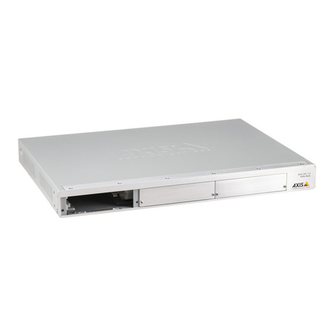
AXIS 291 1U Video Server Rack

AXIS Video Server Rack Installation Guide Page 3
ENGLISH
Axis Rack Mounted Video Server Solution
This installation guide describes the hardware installation of the AXIS 291 1U Video Server Rack,
which can hold up to 3 Axis blade video servers. To install the Axis video server on the network,
please see the video server’s own installation guide.
Hardware Inventory
Please contact your dealer if anything is missing or damaged.
Power cord plug variants
Mounting kit
Please contact your dealer if anything is missing or damaged.
Qty Item Models/variants/notes
1 Video server rack AXIS 291 1U Video Server Rack
2 Cover plates Front panel cover 1U
1 AC power cord • Europe
•UK
• US, Canada, Japan
• Australia
•Switzerland
•Denmark
•Southkorea
1 Warranty Document
1 Mounting kit See separate inventory below
Country Europe UK US,
Canada,
Japan
Australia Switzerland Denmark South
Korea
Power
cord plug
Qty Item Models/variants/notes
4 Rubber foot For placement on flat surfaces
1 Mounting bracket (side) Left
1 Mounting bracket (side) Right
8 M3x8 screw (recessed) For attachment of side brackets
4 M6x20 screw For mounting AXIS Video Server
Rack in equipment rack
3 Terminal connector
block
12-pin, green
The 2 mounting brackets included
in the mounting kit are slightly
different. See the label on each
bracket.
Note:

Page 4 AXIS Video Server Rack Installation Guide
AXIS 291 1U Video Server Rack - Overview
Read the following information to familiarize yourself with the AXIS 291 1U Video Server Rack,
making note of where the connectors and indicators are located.
Power Connector - Input power: 100-240V AC, 50-60 Hz, 1.9A
I/O Terminal Connector(s) - provides the physical interface to the functions supported by the Axis
blade video server. For more information see page 8.
Power & Network LEDs - The 10/100 LED flashes red for 10 Mbit, and flashes green for 100 Mbit.
The 1000 LED flashes green for 1 Gbit. The power LED shows steady green when the rack is
powered.
Network Connector - Axis blade video servers are designed for 10/100/1000 Mbps networks and
are connected via a standard RJ-45 connector.
Placement requirements
The location the AXIS 291 1U Video Server Rack is used in must meet the following requirements:
• Ambient temperature: 0° to +45°C (32° to 113°F)
• Relative humidity: 20-80%
• Power source within 1.8 meters
• Minimum 5cm free space on each side, to ensure adequate ventilation
• No excessive dust
Placement on a shelf/table
1. Attach the 4 rubber feet to the underside of the
unit, as illustrated here.
2. Place on a flat surface. Note that the AXIS Video
Server Rack with cables weighs up to 6kg. Check
that the surface can support this weight.
Power
Connector
Power & Network
LEDs
I/O Terminal
Connector 3 Network
Connector
I/O Terminal
Connector 2
I/O Terminal
Connector 1

AXIS Video Server Rack Installation Guide Page 5
ENGLISH
Installation in a 19” equipment rack
Requirements
• Pozidriv screwdriver #1
• Pozidriv screwdriver #3
• The rack must be braced and bolted to the floor.
• The AXIS Video Server Rack must be grounded to the same ground as the equipment
rack.
When mounting the AXIS Video Server Rack in a rack, never stack other units directly on top - the
mounting brackets are not designed to support more than 1 unit. Each unit in the rack must be
secured with appropriate brackets. Place the heaviest units at the bottom of the rack.
Attaching the brackets
The 2 mounting brackets are slightly different. To tell these apart, see the label on each bracket. See
also the illustration on page 3.
1. Remove the screw shown here from
each side of the unit. These will be
replaced by the screws used to fasten
the bracket.
2. Using the recessed M3X8 screws,
fasten the bracket to the side of
the unit. Do not use the screw that
was removed in step 1.
3. Slide the AXIS Video Server Rack
into the equipment rack. Insert the
M6X20 screws and tighten.

Page 6 AXIS Video Server Rack Installation Guide
Connect power
The AXIS Video Server Rack has no On/Off switch or button and will power up as soon as the power
cord is connected. Detaching the cord is the only way to remove power, so it is important to locate
the unit so that the power cord is easily accessible. Please ensure that the correct AC power cord for
your country is used.
Note also the following requirements and restrictions:
• To prevent the risk of electrical shock when in contact with the unit casing, only earthed/
grounded power cords should be used to power the AXIS Video Server Rack.
• Protection against overcurrents, short circuits and earth faults should be provided in the build-
ing installation.
• The AXIS Video Server Rack is intended for indoor use only, and only for TN and IT power sys-
tems.
• The AXIS 291 Video Server Rack is designed for use with Axis Blade Video Servers only.
• If a foreign object is accidently dropped into the Video Server Rack, always disconnect power
before attempting to remove the object.
Power specifications
• Input voltage 100-240V AC, at 50/60Hz
• Input current: 1.9A
• Power consumption with 3 x AXIS 243Q: Max 80W

AXIS Video Server Rack Installation Guide Page 7
ENGLISH
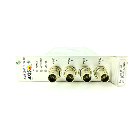
AXIS blade video servers
S/N - (serial number) is identical to the unit’s MAC/Ethernet address,
e.g. 00408C1A2B3C = 00-40-8C-1A-2B-3C.
P/N - is the product’s model number.
Bus Connector - This is the physical interface to the I/O terminal connector on the rack.
DIP Switches (4-port models) - Each video input has a corresponding line termination DIP switch.
Axis blade video servers are supplied with the line termination enabled for each input; i.e. with the
DIP switches set to ON (down position). To connect the video server in parallel with other
equipment, disable the input termination by setting the corresponding DIP switch to OFF (up
position). Failure to do so may affect the image quality negatively.
DIP Switches (1-port models) - These models can accommodate either composite or Y/C video.
The type to use is determined by the DIP switch settings. 1-port AXIS blade video servers are
supplied configured for composite video input, as shown in the table below.
Switch 1 2 3 4
Description 75 ohm video in
termination
75 ohm video out
termination
Connects video in
and video out
Not used
Composite video
input
on off on n/a
Y/C video input on on off n/a
Bus
Connector
DIP Switches
S/N & P/N label
4 Video inputs

Page 8 AXIS Video Server Rack Installation Guide
Mounting AXIS blade video servers
The AXIS Video Server Rack can accommodate 3 Axis blade video servers. The slots for these are
numbered 1-3 from left to right, as seen from the front. The I/O connectors for each slot on the rear
panel are also numbered.
1. Remove a front panel cover from the slot in which the video server will be mounted. This is
done by unfastening the screw on each side of the cover.
2. Slide the video server into place, using the guides as an aid. The dip switch for setting the line
termination should be visible on the top edge.
3. Fix the video server in place, using the screws from the front panel cover.
Note: Leaving an empty slot on the AXIS Video Server Rack open is not permitted. Front panel covers must
be used on all empty slots.
The I/O Terminal connector
The AXIS Video Server Rack server provides an I/O terminal connector for each Axis blade video
server (see illustration on page 4). This is used for connecting external equipment, in applications
for e.g. motion detection, event triggering, time lapse recording, alarm notification via email, image
storage to FTP locations, etc.

AXIS Video Server Rack Installation Guide Page 9
ENGLISH
Connector interfaces
The interfaces available via the 12-pin I/O terminal connector are as follows:
•4 Digital inputs - used for e.g. a pushbutton. If the button is pressed, the state changes
and the input will be active (shown under Event Configuration > Port Status). (AXIS
241Q Blade, AXIS 241S Blade, AXIS 243Q, AXIS 240Q)
•4 Transistor outputs - for e.g. alarm devices that can be activated from Output buttons
on the Live View page, or as an action to an Event Type. The output will show as active
(in Event Configuration > Port Status) if the device is activated.
• 10 configurable I/O connectors (AXIS Q7406)
•RS-485 interface, for e.g. Pan/Tilt/Zoom devices (see www.axis.com for drivers)
• Auxiliary power
Connector pinout
To connect input/output devices to the I/O terminal connector:
1. Referring to the table above, loosen the corresponding screw on top of the pin on the green
connector block.
2. Push the cable into the connector block and secure it by fastening the screw.
3. Once all devices are connected, push the connector block into the terminal connector on the
rear panel of the AXIS Video Server Rack.
For compatible replacement connectors, contact http://www.phoenixcontact.com, quoting: MC1.5/
12-ST-3.81 (art no 1803675).
Pin AXIS Q7406 AXIS 243Q AXIS 241Q Blade,
AXIS 241S Blade, AXIS 240Q
1 +12V out, 100mA +12V out, 100mA +12V out, 100mA
2 GND GND GND
3 Channel 1, Configurable I/O 1 Channel 1, Input 1 Input1
4 Channel 2, Configurable I/O 1 Channel 2, Input 1 Input 2
5 Channel 3, Configurable I/O 1 Channel 3, Input 1 Input 3
6 Channel 4, Configurable I/O 1 Channel 4, Input 1 Input 4
7 Channel 5, Configurable I/O 1 Channel 1, Input 1 Output1
8 Channel 6, Configurable I/O 2 Channel 2, Input 1 Output2
9 Channel 1, Configurable I/O 2 Channel 3, Input 1 Output3
10 Channel 2, Configurable I/O 2 Channel 4, Input 1 Output4
11 Channel 1, RS485A Channel 1, RS485A RS485A
12 Channel 1, RS485B Channel 1, RS485B RS485B
AXIS 291 1U Installation Guide v2.3 June 2009
Copyright © Axis Communications AB, 2007-2009 Part No. 35857
POWERPOWER
1
2
3
4
5
6
Assembly of multi-channel video server
Serial numbers for each blade video server affixed here
Other manuals for 291 1U
3
Table of contents
Other Axis Server manuals

Axis
Axis 282 User manual

Axis
Axis 241Q Blade User manual

Axis
Axis Audio Manager Pro C7050 Mk III User manual

Axis
Axis 700 User manual

Axis
Axis Q7900 Rack User manual

Axis
Axis AXIS 243Q Blade User manual

Axis
Axis 241Q Blade User manual

Axis
Axis C7050 User manual

Axis
Axis 7000 User manual

Axis
Axis 240Q Blade User manual