Ayra TDC Flower Power User manual

TDC Flower Power
LED Flower Light Effect
User Manual
The information in this user manual is subject to change at any time without notice.
Version: 1.0 Date of creation and author's initials: 07-10-2019 RV Revision date and author's initials: -
Introduction
Thank you for purchasing the Ayra TDC Flower Power. This versatile light effect is fitted with a colour-filled
light source and specially designed, rotating optics capable of throwing hundreds of light bea s across the
roo . This anual provides all the infor ation you need to know about the product before you start using it.
We advise that you read this user anual in its entirety before unpacking the contents of the box, so that you
are fa iliar with all of the functionality that this product has to offer. Please ake sure to check that all of the
parts and accessories listed below under 'Box Contents' are included in the package. In the event that the
TDC Flower Power does not function properly, or if you have any issues while operating it, please re ove
the plug fro the power socket and contact your retailer for assistance.
Box Contents:
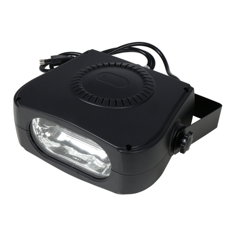
- Ayra TDC Flower Power Fixture
- Suspension bracket
- Hardware (2x tightening knobs, 2x rubber rings)
- Connection cable fro IEC C13 to Schuko, 1.5 ²
Please inspect the de ice and included accessories
Should you discover that either the device or one or ore of the included parts have been da aged or
rendered defective while in transit, please contact your dealer directly.
Please note that the pictures in this user manual serve illustrative purposes only and may differ from the
actual product.
The information in this user manual is subject to change at any time without notice.
Version: 1.0 Date of creation and author's initials: 07-10-2019 RV Revision date and author's initials: -

Safety Instructions
Everyone involved with the installation, operation and aintenance of this device ust:
- Be qualified.
- Be skilled.
- Have read the instructions included in this user anual.
- Be sure that neither the device nor the included accessories are da aged. Should the device or the
included accessories be da aged, please contact your retailer for ore infor ation.
- Ensure that the device is in good working condition and is safe to operate. Please follow the advice and
instructions as they are described in this user anual.
Da age caused by isuse and/or odifications ade to the device are not covered by the warranty.
This device does not contain any parts that can be repaired or replaced by the user. Should aintenance or
repairs be necessary, they ust be handled by a qualified technician.
The light source of this device is not replaceable. If the light source no longer functions, the entire device
needs to be replaced.
Important information regarding health and safety:
- Do not re ove any labels or stickers fro this device.
- Do not leave any cables lying around.
- The device should not be opened up and any hardware or software that ay be present should not be
odified.
- To achieve opti al perfor ance, any inputs on the device should not be fed with a signal higher than
necessary.
- The device should only be used indoors; contact with water, rain and oisture should always be avoided.
Do not place any objects containing liquid on top of the device.
The information in this user manual is subject to change at any time without notice.
Version: 1.0 Date of creation and author's initials: 07-10-2019 RV Revision date and author's initials: -
WARNING!
Keep this de ice away from moisture, water and rain to a oid the chance of electric shocks!
WARNING!
Only connect this de ice to a suitable power socket. This de ice functions on a specific power
oltage. If it is plugged into a power socket with a different oltage, it could result in permanent
damage and e en dangerous situations such as fire or electric shocks.
WARNING!
Be careful when operating this de ice. Touching the wires that are connected to the mains,
inside or outside the de ice, could result in electric shocks!

- Re ove the device fro any nearby fla es or heat sources; do not place it near fla able fluids, gasses
or objects.
- Disconnect this device fro a power source if it is not being used for a long period of ti e; if aintenance is
necessary, or if it needs to be cleaned.
– Do not pull or tug on the cable to re ove a connector as this ay cause da age.
- Do not use any cables other than the ones described in this anual. Do not use defective cables. Please
contact your retailer if the included or necessary cables do not function properly with this device.
- Only use this device with a stable AC power supply.
- Only use this device with power fro a grounded power source.
- In the event that the device is exposed to extre e te perature changes (e.g. transported fro a cold
outdoor environ ent into a war indoor environ ent), it should not be turned on until it has reached roo
te perature. This is necessary to prevent oisture (condensation) fro for ing inside the device, which
could lead to electric shocks.
Guidelines and operation of this de ice:
- This device is intended for use by professionals on stage, in theatres, in clubs and in si ilar entertain ent
locations.
- This device is not suitable for use by children and should always be operated by an adult.
- This device is designed to create light effects for entertain ent purposes. It is not suitable for household
illu ination.
- This device ay only be used in a suitable environ ent where no da age to the device can occur. Do not
use the device in oist or dusty environ ents such as:
- indoor swi ing pools where chlorine is used
- beaches or any location where sand and/or salt is present
- outdoors
- indoors in spaces where intense heat sources are present, or where it can reach te perature levels
that would be considered unco fortable for a person
- Avoid i pact and collisions during use and transport. Do not ove or transport the device while it is in use.
Avoid using excessive force when installing and operating the device.
- Any user ust beco e fa iliar with the functions of this device before using it.
- Should the device not be used in the anner described in this user anual, da ages or even injuries could
occur. Ayra cannot be held responsible for any injuries or da ages that occur as a result of i proper use of
this product.
Storage and transport:
- This product was designed for obile use. Please only transport the device in the original packaging, or in
a flight case with a suitable foa inlay.
- This device was not designed for per anent (24/7) use. The expected lifespan of the device will not be
affected by occasionally turning the device off. Disconnect the device or turn off the power when it is not
actively in use.
- If the device is not in use for a long period of ti e, it should be disconnected and stored in a dust-free
environ ent.
- Do not expose the device to extre e te perature differences.
Housing:
- Inspect the device's housing frequently and always just before use. Avoid operating the device if there are
any large dents or cracks, or if screws are issing. Do not use the device if the housing is not in good
condition.
Contact your dealer or a qualified technician if you are unsure about the state of the device.
- Check the device and the screws for corrosion. Corrosion ust not be present on this device. Contact your
dealer or a qualified technician if you find any corrosion on the screws.
Every power and signal connector should be securely attached. Do not use the device if the connectors are
not secure.
- Avoid dust and dirt build-up. Clean the device once a onth by disconnecting it fro the power supply and
wiping it down with a dry or slightly oist cloth. If the device is used frequently, the cleaning intervals should
increase.
The information in this user manual is subject to change at any time without notice.
Version: 1.0 Date of creation and author's initials: 07-10-2019 RV Revision date and author's initials: -
Symbol Explanation:
WEEE: Ensure that this device is disposed of properly. This product falls under the WEEE
(Waste Electrical and Electronic Equip ent) directive. The require ents of this directive apply
to all anufacturers and producers of electronic devices in the EU. Do not throw this product
away with regular rubbish. Please contact your local authority for ore infor ation about how
to recycle and dispose of these products in your region. By recycling this product in the proper
anner, we can work together to ensure that we can continue to enjoy these kinds of
products and still protect the environ ent as uch as possible fro pollution.
CE: The CE logo indicates that this product eets the European nor s and require ents to
which it ust legally confor .
Suitable for indoor use only: this product was only designed for indoor use. The axi u
environ ental te perature ust not exceed 40 degrees Celsius (104 degrees Fahrenheit).
Contact:
Ayra professional lighting products
Verrijn Stuartweg 18
4462 GE Goes
The Netherlands
Please do not send any products to this correspondence address.
Should you wish to send in a product for repairs or for a refund, please contact your dealer for an RMA
re uest (Return Merchandise Authorisation).
The information in this user manual is subject to change at any time without notice.
Version: 1.0 Date of creation and author's initials: 07-10-2019 RV Revision date and author's initials: -
Operation Guidelines for this De ice
1. Light Output
2. Suspension bracket
3. LED Display with Menu buttons
4. DMX input via 3-pin XLR
5. DMX output via 3-pin XLR
6. Power input with fuse co part ent
The information in this user manual is subject to change at any time without notice.
Version: 1.0 Date of creation and author's initials: 07-10-2019 RV Revision date and author's initials: -
25
6
1
3
4

Operation and Mounting
To activate the device, plug it into a ains socket. Once it's connected to an active power source, it will turn
on auto atically.
The device cannot be operated while it is still starting up and the Menu screen displays ‘rST’. Once the
device has fully started up, it will auto atically ju p to the last ode and setting. Operation odes and other
settings shown on the display can now be adjusted or changed via the enu buttons.
If a DMX signal is detected, the device shall auto atically switch to DMX ode and the DMX address that
was last used. For a new device, this is usually DMX address 001. The DMX address can of course be
changed via the display and enu buttons.
The functions, odes and settings can be changed by using the display and enu buttons. Push ‘Enter’ to
select a function or to confir a change. Push ‘Up’ and ‘Down’ to change any values and push the ‘Menu’
button to return to the ain enu. A few seconds after confir ing a setting by pressing ‘Enter’, the device
shall auto atically return to the ain enu and perfor the set actions. This can be sped up by holding the
‘Menu’ button down for 2 seconds after confir ing a setting by pressing ‘Enter’. This is usually done after
adjusting the working ode or DMX address.
The Menu includes the following options and fuctions:
Display Mode Function
ADDR / A001 DMX Address Configuration Address A001 … A512
CHND Channel Mode Selection 10CH
SLND Slave Mode Master
Slave
SHND Select Built-in Shows Show ode AU0-8
SOUND Sound-Controlled Mode Mode: ON / OFF
SENS Sound Sensitivity 0 - 100: Sensitivity in %
DNST DMX Signal Loss Mode Selection NAST - Master- odus
LAST – Last signal received
BLND – Blackout ode
LED LED Display Off / On when not in
use
ON/OFF
DISP Display Inversion Display Invert, disp - dslp
REST Reset Function Restart the device
TEMP Te perature Display Displayed in Degrees Celsius
F HS Duration of use 0000 – 9999 Hours of use
VER Fir ware Version Displays current version of fir ware installed.
This cannot be adjusted or changed
The information in this user manual is subject to change at any time without notice.
Version: 1.0 Date of creation and author's initials: 07-10-2019 RV Revision date and author's initials: -
An explanation of all a ailable functions can be found below:
ADDR: With this function, you can deter ine the DMX start address of the device. Set it channel 001, and
the device will respond to DMX channel 1. Set it to channel 003, then the device will respond to DMX
channel 3 and so on.
CHND: This device has a single 10-channel DMX ode in which it can be fully operated via 10 channels,
each controlling a different function.
SLND: Using the Master / Slave Mode, it’s possible to connect several devices of the sa e type with one
another, via DMX 3-pin XLR cables so that they perfor exactly the sa e ove ents and functions at the
sa e ti e. Therefore, single devices do not respond individually (or chaotically) and this results in a
co pletely coordinated show. In the Master / Slave function, the first device in the circuit is set as the Master
and does not receive DMX signal.
PLEASE NOTE: When Slave ode is activated, the device shall wait for a signal fro the designated Master
device. Selecting an auto atic or sound-controlled ode is then not possible! To cancel the Slave ode,
enter the ‘SLND’ enu and select ‘NAST’. This then sets the device to Master ode and the stand-alone
functions can then be activated once ore.
SHND: In this ode, one of the 8 built-in show progra es can be selected. These can be sound reactive
and synchonise to usic if the icrophone has been activated. If the icrophone is switched off, the speed
of each progra e can be anually adjusted.
SOUN: Here, the in-built icrophone can be set to On or Off.
SENS: This ode allows you to set the sensitivity of the in-built icrophone. The further the device is
installed fro the sound-source, the higher the sensitivity of the icrophone needs to be so that the sound is
registered and the device responds accordingly and in ti e to the usic. The icrophone is able to
withstand high sound pressure. However, if the sound is loud and the sensitivity is high, the icrophone will
find it ore difficult to register the beat. Experi ent with the sensitivity and distance fro the positioning of
the device to ake sure you’re getting the best possible signal and opti u perfor ance.
DNST: Use this function to set what the device will do in the event of DMX signal drop-out or loss. When set
to Master ode, the device shall start an in-built progra e. In the LAST ode, the device re ains in the
last active DMX co and received. In the Blackout ode, all settings return to zero and that device no
longer oves or gives light.
LED: When the LED display is not in use, it can be switched off. By setting ‘LED’ to ‘Off’, this will prevent red
sy bols fro illu inating when the device is being used in dark spaces. If you press of the enu buttons,
the display shall i ediately light up and show all necessary infor ation. If the display is not used, it shall
auto atically switch off again within 30 seconds.
DISP: This function is useful when the device is suspended and the display screen is upside down. Use this
function to flip the screen so that it can be easily read when the device is suspended.
REST: When this function is activated, the device will be restarted. This has the sa e affect as turning the
power off and on again. When it is reset, the device will recalibrate, reboot and return to the last selected
operating ode or DMX signal (if detected).
TEST: When the device needs to be checked, use the ‘TEST’ function to test one or ore devices at the
sa e ti e. The device(s) shall continuously runs through a progra e within which the LEDs are tested so
that any deviations or defects can be easily detected. The device shall continue to repeat the progra e
until it is anually interrupted (when you switch the device to sound control, for exa ple).
TEMP: The in-built te perature sensor registers the internal te perature of the device. The te perature can
be checked here and is displayed in Degrees Celsius.
The information in this user manual is subject to change at any time without notice.
Version: 1.0 Date of creation and author's initials: 07-10-2019 RV Revision date and author's initials: -

HOUR: If this device is used professionally or rented, it should be regularly aintained and inspected in
between use. The HOUR function shows exactly how long the device has been in use. This a ount
accu ulates over ti e as long as the device is being used and cannot be anipulated by the user.
VER: Here, the current fir ware version is displayed. This cannot be changed or adjusted.
The information in this user manual is subject to change at any time without notice.
Version: 1.0 Date of creation and author's initials: 07-10-2019 RV Revision date and author's initials: -

Operation Modes
Please find a clear explanation of the differences between all available Operation Modes below and how they
are affected by the enu functions listed above.
Auto:
In Auto Mode, you can select one of the Operation Modes in which the device is not dependent on external
factors such as DMX signals, aster signals or sound. Here, one of the basic progra es can be selected
such as setting the alternating speed or correcting the intensity.
Sound:
The sound-controlled ode or ‘sound ode’ uses an in-built icrophone that registers the beat of usic and
a runs a progra based on this. For exa ple, the device can ove in virtual synchronisation with any usic,
providing an auto atic light-show.
When no usic is detected or only highs are present in the usic due to a break, the device will continue its
progra at a slower pace. As such, the light show does not appear to co e to a stand still. As soon as sound
is registered by the icrophone once ore, the device shall continue its progra in synchronisation with the
beat.
Sla e
In Slave Mode, it is possible to connect several devices of the sa e type with one another so that they
perfor exactly the sa e ove ents and functions at the sa e ti e. Therefore, single devices do not
respond individually (or chaotically) and this results in a co pletely coordinated show. In theory, by adding a
DMX booster, an unli ited nu ber of Slave devices can be linked to one Master device. Initially, no proble
would occur if 4 devices were linked and no DMX booster were added.
Please note: If you link devices of a different type or brand (even if they appear to have the sa e function),
chaotic or strange behaviour can occur. This is often because certain functions are linked to the incorrect
channels. This applies to DMX lighting of all types and brands.
DMX
The DMX Mode is the ost co prehensive ode for opti u control over all functions of this device. Via
DMX, it is possible to control either a li ited or large a ount of functions via a DMX controller or DMX
software.
The device can be set to different channel odes so the channel layout (included below) is in align ent with
the layout of your DMX circuit and with the functions you want to use.
8CH mode:
CH Function Value
1 Master Di er 0-100% 000-255
2 Stroboscope Speed 000-255 Fast to slow
3 Rotation 000-200 Indexing
201-230 Clockwise rotation
231-255 Anti-clockwise rotation
4 Rotation Speed 000-255 Slow to fast
5 Red 0-100% 000-255
6 Green 0-100% 000-255
7 Blue 0-100% 000-255
The information in this user manual is subject to change at any time without notice.
Version: 1.0 Date of creation and author's initials: 07-10-2019 RV Revision date and author's initials: -

8 White 0-100% 000-255
The information in this user manual is subject to change at any time without notice.
Version: 1.0 Date of creation and author's initials: 07-10-2019 RV Revision date and author's initials: -

Installation and Connection Instructions
Now you know how the TDC Flower Power works. So that the device is used in the correct and safest way,
please ake sure to follow the installation and connection instructions.
Make sure that children do not have access to the device or any connecting cables. If there are children
present, ake sure that they are supervised. Since the device can be placed upright or be suspended, it is
possible for children to pull on any connecting cables and cause the device to fall. To prevent any accidents
or injury, this ust be taken into account whenever the device is being positioned and/or installed.
Upright use
When you want to place the TDC Flower Power in an upright position, ake sure that the device is placed on
a stable surface such as a table, DJ booth or bar. The TDC Flower Power is not fitted with rubber feet to grip
the ground and stabilise the device. As such, always ake sure that the light is positioned on a stable
surface and that any cabling is secured so that no one can trip and knock or pull the device over.
The best thing to use for stand-alone, upright use of this device is a ‘Floor Cross’. This floor stand is
designed for spot lighting fixtures and effects. This way, you are sure that the device is aways kept stable.
Suspended use (brackets)
Should you want to suspend the TDC Flower Power, use the suspension brackets, tightening knobs and
rubber rings included.
Place the rubber rings between the bracket and the fixture. Then tighten the knobs on both sides to ake
sure that the bracket is secure.
If you want to suspend the device with a half-coupler or G-hook, this can be done by using the pre-drilled
holes in the bracket. Standard hooks and/or brackets for 35 or 50 tubes (trusses or light stands) are
available fro your local retailer.
Hardware for ounting the TDC Flower Power to the wall, ceiling, or bea is not included. Contact a
specialist if you're not sure what hardware is required for your situation. A wooden bea and stone wall
require different ounting ethods.
When the TDC Flower Power is suspended, you will need to attach a safety cable to the fixture. This is not
included but is available at your local retailer. The device is fitted with an attach ent point for hooking a
safety cable. Once hooked on, the cable can be wrapped around the truss or light stand and attached once
ore to the sa e hook. This ensures the device is secure and prevents it fro falling, even if one or both of
the brackets should co e loose and fail.
Ensure that the safety cable has a load capacity of 10x the weight of the ar ature and that the device can
not fall farther than 30c . You can wrap the safety cable around the truss or light stand several ti es to
ensure the fall is as short as possible. The shorter the fall, the less chance of da age or injury.
Light source
The TDC Flower Power uses powerful LED odules that are ade even ore powerful by a special lens
that co bines and focuses these bea s, uch like a agnifying glass. Since the hu an eye cannot adjust
quickly enough to sudden and intense exposure to the level of brightness this device produces, never look
directly into the lens at close range. While it won't result in per anent da age, it can cause te porary blind
spots which ay cause disorientation and disco fort.
Cooling
The TDC Flower Power is cooled by a ventilation fan fitted in the housing. This fan activates when the device
is switched on. Make sure the fans and vents are not blocked and regularly check that they are functioning
nor ally. Be aware that should the fans beco es clogged with substances like dust, s oke and oisture,
this ay i pair operation and shorten the life-span of the device.
The information in this user manual is subject to change at any time without notice.
Version: 1.0 Date of creation and author's initials: 07-10-2019 RV Revision date and author's initials: -

Parts and repairs
This product does not include spare parts and can not be repaired by the user. Any inspections and overall
aintenance should be carried out by a specialist only.
Cleaning and maintenance
Clean the exterior of this device on a onthly basis with a dry, or slightly da p icrofibre cloth. Ensure that
the device is unplugged before cleaning it.
Check that all screws are intact and secured and tighten or replace the where needed. Check all etal
parts of the device for any signs of corrosion. If corrosion is found, the device needs to be checked
thoroughly.
DMX terminator
When using the device in DMX ode, it is co on for a ‘ter inator’ to be used at the end of the DMX
circuit. A DMX ter inator is a ter inal resistor, consisting of a 120 Oh resistor placed between the second
and third pins to eli inate any data reflections. Data reflections can cause strange behaviour in DMX
controlled devices.
DMX-ter inators are sold read- ade but it is possible to solder a 120 Oh resistor between the second and
third pins of a standard, ale XLR connector.
The information in this user manual is subject to change at any time without notice.
Version: 1.0 Date of creation and author's initials: 07-10-2019 RV Revision date and author's initials: -

DMX Lighting Troubleshooting
If you have a proble with your DMX light effect, please consult the troubleshooting section for possible
solutions. If, after consulting this section, the proble re ains unresolved, please contact your retailer for
ore infor ation and/or help.
This troubleshooting section contains infor ation on how to solve the ost co on DMX light effect
proble s, but it does not and cannot cover every eventuality.
Problem Possible Cause Solution
The device can not be turned on The fuse is blown Check the fuse to rule out if it is
blown or not. If it is blown, replace
it with a new fuse of the sa e type
and class.
Power cable not plugged in Check if the power cable is
properly connected to the device
and plugged into an active power
socket.
The device is not reacting to DMX
signals
Incorrect DMX start address Check if the device has been set
to the correct DMX start address
DMX controller is set to ‘Blackout’ Make sure the ‘Blackout’ function
on the DMX controller is not
activated
Make sure the polarity switch on
the DMX controller is set correctly
Try to reverse the DMX polarity
switch on the DMX controller.
The device is not reacting, there is
no DMX signal indication
Make sure the XLR cables are
connected properly and are not
defective. Replace if necessary.
The device does not react to
sound/ usic
Incorrect operation ode Make sure the sound-activated
ode has been selected.
The internal icrophone sensitivity
is too low
Check the icrophone sensitivity
level and increase it if necessary.
The speaker is too far away, or is
not producing enough low tones
Place the light effect closer to a
speaker (or vice versa) and/or
increase the low-frequency level.
The built-in icrophone is not
triggered by high tones.
The a ount of projected light is
ini al
Dirty or dusty optics Clean the lens and/or other optics.
Di er is not co pletely open Check if the di ers on the
spotlights the selves and/or if the
aster di er is co pletely open.
Also, check the colour balance
settings.
The DMX signal appears to be
interrupted and so e devices are
flashing or behaving strangely
Da aged/defective cables Check and replace the DMX
cables if necessary.
Power interference on the DMX
signal
Avoid connecting signal cables
parallel to power cables.
DMX ter inator issing Close the DMX circuit with a DMX
ter inator
The information in this user manual is subject to change at any time without notice.
Version: 1.0 Date of creation and author's initials: 07-10-2019 RV Revision date and author's initials: -

Signal loss or interference in the
DMX circuit
Close the DMX circuit with a
ter inator or connect a booster
after axi u 32 fixtures.
The device is not reacting properly
to DMX co ands
Incorrect DMX channel ode Check that the correct DMX
channel ode is set
The operation ode can not be
changed
The device is in Slave ode If the device is in Slave ode, it
will wait for a aster signal unless
there is a DMX signal present. Set
the device to Master to activate the
sound-controlled or auto ated
operation odes.
The information in this user manual is subject to change at any time without notice.
Version: 1.0 Date of creation and author's initials: 07-10-2019 RV Revision date and author's initials: -

Technical Specifications
Features:
- LED Flower Power light effect
- Rotating optics for special light rays
- 25W RGBW LED light source
- LED Display with Menu buttons
- Diverse operation odes
- Auto atic odes
- Sound / Music-Controlled ode with adjustable sensitivity
- Master / Slave function
- DMX controlled via 8 channels
- Operation odes: Auto atic, Sound / Music-Controlled, Master / Slave, DMX
- DMX connection via 3-pin XLR input and output
Technical Details:
- Power supply: 100-240V AC, 50/60 Hz
- Maxi u power consu ption: 30 Watt
- Power factor: 0.6
- Fuse: F3AL250V
- Light source: 1x 25W RGBW ultichip LED
- Maxi u functioning te perature: 0°C to 40°C
- Maxi u housing te perature when in nor al use: 55°C
- Di ensions: 210 x 90 x 130
- Weight: 1.6kg
Projection Data:
- Bea angle: 120 Degrees
- Red projection: 125-145 Lux at 1
- Green projection : 230-260 Lux at 1
- Blue projection: 55-65 Lux at 1
- White: 330-360 Lux at 1
The information in this user manual is subject to change at any time without notice.
Version: 1.0 Date of creation and author's initials: 07-10-2019 RV Revision date and author's initials: -
This manual suits for next models
1
Table of contents
Other Ayra Light Fixture manuals

Ayra
Ayra IntenZ CB700 User manual

Ayra
Ayra ERO 3108 User manual

Ayra
Ayra Armageddon 648 RGB LED User manual

Ayra
Ayra Ero Minibeam 12 User manual

Ayra
Ayra ERO 030 User manual

Ayra
Ayra ITA COMPACT series User manual

Ayra
Ayra TDC Diamond Scan User manual

Ayra
Ayra ERO L90 User manual

Ayra
Ayra Armageddon 648 W LED User manual

Ayra
Ayra Compar Kit Jr. User manual
Popular Light Fixture manuals by other brands

LED World
LED World FA60M50-5M-24V-RGB Important instructions

Dals
Dals MSLWALL-CC installation guide

Polarlite
Polarlite 1646407 operating instructions

StudioDesk
StudioDesk LED02 Assembly manual

ADJ
ADJ Mega GO Bar 50 RGBA User instructions

Larson Electronics
Larson Electronics LED T Series instruction manual