Ayrton DREAMPANEL TWIN User manual

USER MANUAL V.1
ENGLISH VERSION
12 22 2015


USER MANUAL _ 3
SUMMARY
Introduction
Safety instructions
Conditions of use
Presentation and features
Dimensions
Description
Installation instructions
Installation method using truss hooks
Artnet connection
The DreamPanel Twin DMX address setting
Control Panel
DreamPanel Twin control panel menu– option details
Master/Slave Mode settings
Led mapping
DMX Chart
Error Messages
Care and maintenance
Technical Specifications
Warranty
4
4
4
5
6
7
7
8
8
8
8
9
12
13
14
16
16
17
18

USER MANUAL _ 4
INTRODUCTION
Thank you for selecting the AYRTON DREAMPANEL TWIN luminaire.
WARNING !
This product is not suitable for household use.
You now own a professional lighting unit that offers endless possibilities.
Before installing, make sure that no damage was done to your luminaire
during transport. If this is the case, do not use the product and immediately
contact your authorized AYRTON dealer.
For your own safety and that of others, please read this instruction manual
carefully before installing the unit.
Anyone involved in installing, operating or servicing the DREAMPANEL
TWIN must:
• Be a qualified, authorized professional
• Strictly follow the instructions in this user manual.
Please take the time to read this manual carefully and thoroughly before
installing and operating the luminaire. You should have a good knowledge
of its operating conditions and all pertinent product information.
After you have become familiar with this manual, we recommend that
you keep a copy for future use. All the information found in this manual
is subject to change without notice. AYRTON reserves the right to modify
and upgrade its range of products, with no obligation to integrate these
changes into products already sold.
SAFETY INSTRUCTIONS
Please read the safety instructions and warnings in this manual carefully
before installing and operating the DREAMPANEL TWIN.
WARNING!
Risk of electric shock.
Use caution when handling. This luminaire requires high voltage,
which can result in electric shock.
The DREAMPANEL TWIN left our factory in perfect working condition.
However, if you notice a defect, immediately contact your authorized
AYRTON dealer before use. The manufacturer cannot be held responsible
for damages caused by a failure to follow the safety, installation or
assembly instructions contained herein, or by any modification made to
the luminaire.
Failure to observe the safety, installation or assembly instructions
contained herein, or any modification made to the DREAMPANEL TWIN
luminaire will render the warranty null and void.
Check that the supply voltage does not exceed the maximum authorized
limit. Check that your electrical installation complies with current
standards.
In all cases, make sure that the power cables attached to your
DREAMPANEL TWIN have not been damaged due to cuts and splices or
crushed in any way. Handle these cables with extreme caution while they
are connected to a power source.
Your DREAMPANEL TWIN conforms to Class 1 safety standards. The
unit must be grounded electrically. Make sure that the power source
connected to your DREAMPANEL TWIN is switched off before attempting
any work on it.
Installation and connection to an electrical source must be performed
by an authorized installer. AYRTON declines all responsibility should this
luminaire be installed by an unqualified person.
Never disconnect your DREAMPANEL TWIN by pulling on the power cable!
First unlock the connector lock ring on the power cable until it is fully
disengaged, and then gently pull on the connector to disconnect the cable.
Do not connect or disconnect the power cable of your DREAMPANEL TWIN
with wet hands.
At first use, your DREAMPANEL TWIN may give off an odor. This is a
normal occurrence that should dissipate after a few minutes of operation.
WARNING!
Do not connect or disconnect the power cable at your DREAMPANEL
TWIN if the cable is energized! This could cause arcing and damage
your DREAMPANEL TWIN, requiring repair.
Be careful to power off your DREAMPANEL TWIN by removing the power
plug from the source, before connecting or disconnecting the luminaire.
WARNING!
This unit contains Class 2 LED emitters (EN60625-1): 1994)
This luminaire uses multiple high-power (Class 2) LED-type (Light Emitting
Diode) lamps. Never look directly into the lamps if lit or stand directly in
line with the luminaire if close by.
Installation, removal or replacement of the unit must be performed with
power off to prevent any risk of glare and eye injury.
WARNING!
The fixture quickly becomes very hot during operation.
To avoid risk of burn, never handle or adjust the luminaire while it is
energized and after it has been lit for more than 10 consecutive minutes.
Some parts of the luminaire can reach a high temperature, particularly the
body/radiator. Turn off the luminaire and wait for it to cool before handling.
CONDITIONS OF USE
Your DREAMPANEL TWIN is a moving-head luminaire equipped with
multiple LEDs intended for professional use (e.g., architectural, stage,
television, theater, or museum lighting).

USER MANUAL _ 5
The DREAMPANEL TWIN luminaire has an IP20 protection rating.
It is intended strictly for indoor use. It must never be partially or fully
submerged, even temporarily.
Condensation may form on your DREAMPANEL TWIN in the following
cases:
• Immediately after turning on the heating
• In places with fog or a high level of humidity
• When the luminaire is suddenly moved from a cold to a warm
environment, or vice versa.
In such cases, you must wait until the luminaire readjusts to the ambient
temperature of the room where it will be installed for operation.
Do not shake the DREAMPANEL TWIN while installing or handling.
Do not pull the DREAMPANEL TWIN by one of its cables to move it. Lift the
luminaire by its handles.
Choosing the appropriate place to install the DREAMPANEL TWIN is
essential. The following points should be observed:
• Do not expose it to a heat source.
• Do not install it near flammable materials.
• Be sure that dust or miscellaneous debris cannot clump around the
body of the luminaire as this may interfere with its optimal cooling and
proper operation.
• The DREAMPANEL TWIN must be installed out of reach of the public
and all persons not authorized to operate the luminaire.
We recommend a minimum distance of 20 cm between the outside
surface of the light and the illuminated object. The color mixture of the
DREAMPANEL TWIN can be improved if the illuminated surface is very
close to the luminaire (up to about 50 cm).
Due to the nature of its cooling principle, you should never prevent air
from circulating around the body of the luminaire. You must provide a
minimum clearance of 20 cm around your DREAMPANEL TWIN to allow
for cooling.
The DREAMPANEL TWIN can be installed in a ground pit or any other
confined enclosure only under certain conditions. With this kind of
installation, a system of forced ventilation should be used up to allow
air to circulate freely around the luminaire(s). The air must be constantly
renewed because the luminaire cannot be operated in closed system.
Failure to comply with these requirements may destroy or prematurely
wear the DREAMPANEL TWIN, and AYRTON cannot be held responsible.
Please consult your AYRTON dealer for more information on this type of
installation.
No load should be placed on the DREAMPANEL TWIN. The fixture must
not be installed in such a way as to allow a person, vehicle or any object
to run over or park on it.
Never lay or drop any hard, heavy, or blunt, objects on the DREAMPANEL
TWIN. This includes items made of glass or porcelain (e.g., bottles,
dishware, or glass beads). The luminaire is made of materials such as
plastic and extruded aluminum, making it resistant but not unbreakable.
Objects made of hard materials such as steel or glass that fall on the unit
may cause breakage of the plastic parts or the body. AYRTON cannot be
held responsible for the luminaire’s broken plastic parts or body, which are
not covered under warranty.
The temperature of the room where the DREAMPANEL TWIN is installed
must never exceed 45°C (Ta = 45°C).
The DREAMPANEL TWIN luminaire requires a 110-240 VAC supply
voltage. Check that your luminaires have been installed for an application
that is compatible with this information.
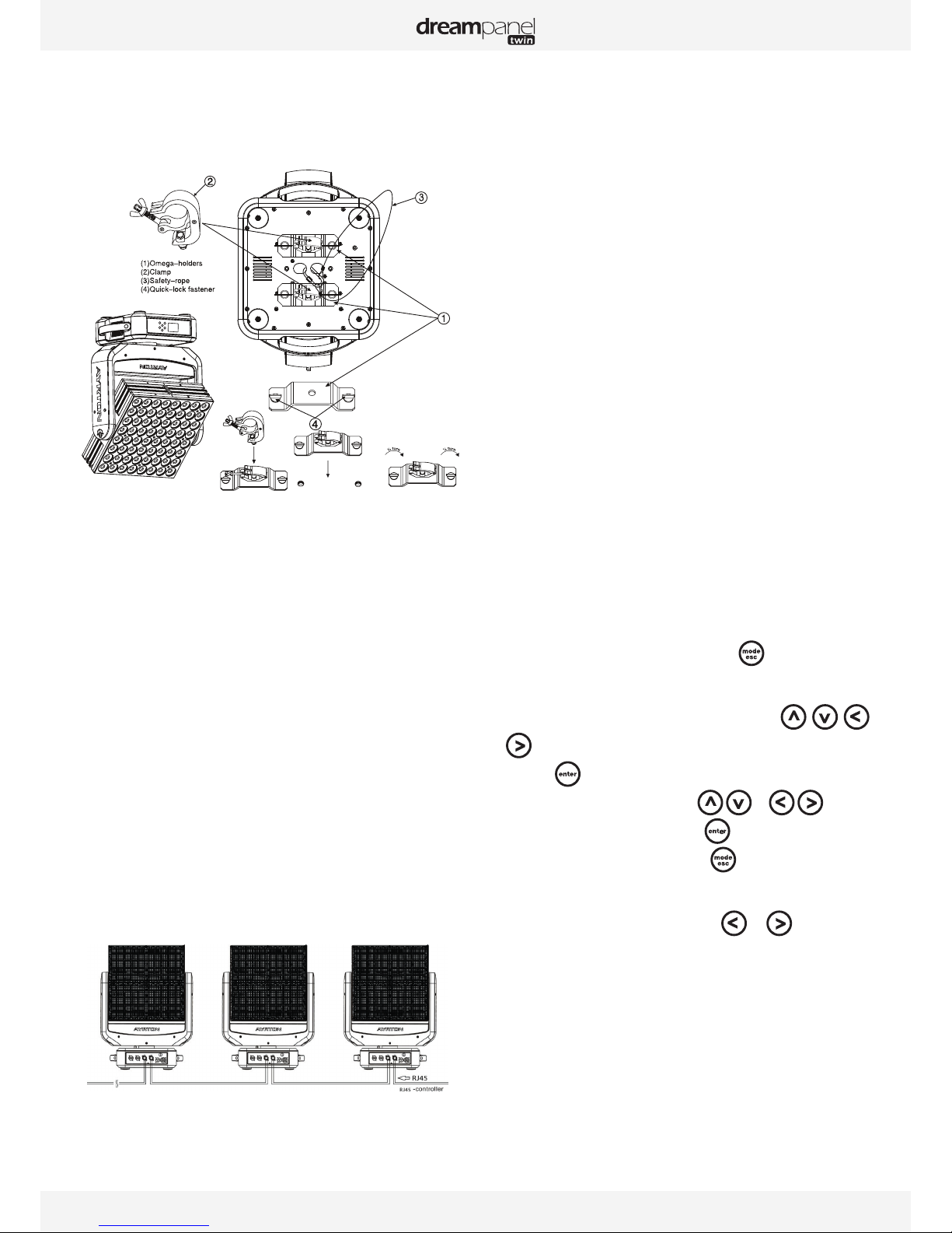
Check that the brackets on which you hang or attach your DREAMPANEL
TWIN can sustain the weight of the luminaire (25kg), taking into
consideration all necessary safety factors.
Do not use your DREAMPANEL TWIN before being familiar with these
recommendations and do not allow unqualified personnel to handle the
product.
To transport your DREAMPANEL TWIN, we strongly recommend that you
use the complete original packaging, including the dense protective foam
inserts.
If your DREAMPANEL TWIN is not being used for a long period, you should
disconnect the luminaire from the power source.
Never dispose of the DREAMPANEL TWIN in a rubbish bin. Ensure that
it is recycled. Please consult the current legislation in your country on
recycling electronic equipment.
WARNING!
The number of daisy chain, or tandem, connections to the
DREAMPANEL TWIN (power input and output sockets on the
luminaires) is limited for safety reasons. The maximum authorized
number of connections is as follows, with the power line protected
by a 10A circuit breaker:
• 2 DREAMPANEL TWIN units on the same source at 230 VAC
or
• 1 DREAMPANEL TWIN units on the same source at 110 VAC.
PRESENTATION AND FEATURES
DREAMPANEL TWIN is a non-waterproof moving head wash light (IP20
protection rating) using the latest generation of high-performance of LED-
type lamps.
This luminaire can be controlled remotely by an external DMX512 signal.
The DREAMPANEL TWIN incorporates multi-chip LEDs using 4 colors:
Red, green, blue and white.
This color-light luminaire operates on the CMY additive color principle and
along with white light can potentially render a palette of 4.2 billion colors.
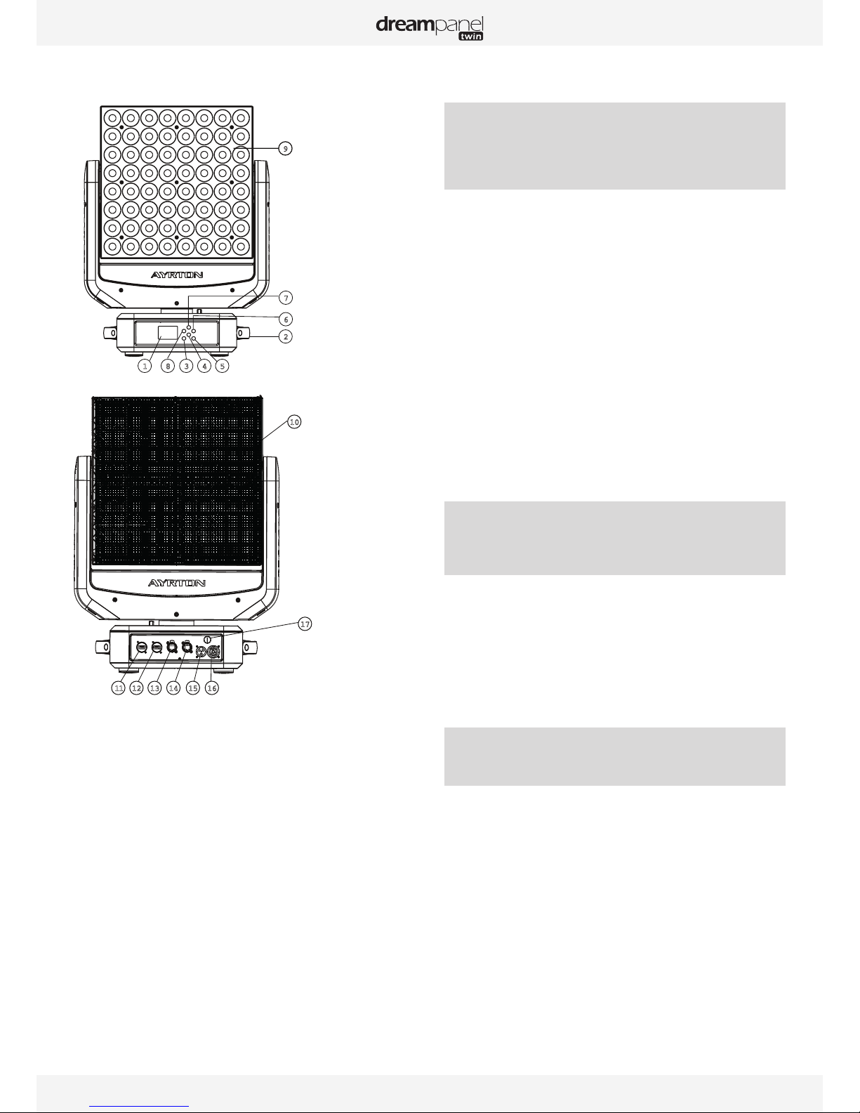
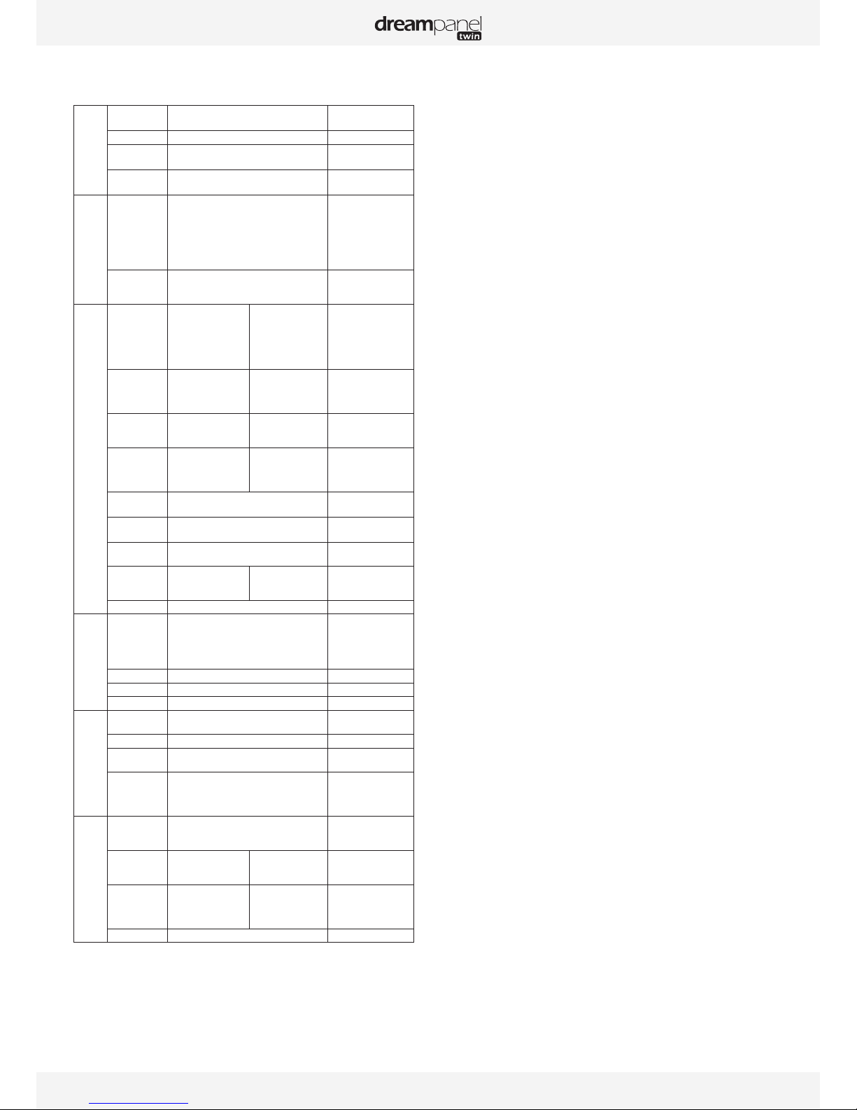
The DREAMPANEL TWIN has a total of 64 LEDs that can be controlled
independently. The luminaire requires from 18 to 272 DMX channels to be
controlled via an external command system that sends a DMX512 signal
(see below for details).
To adjust the settings on the DREAMPANEL TWIN (i.e., DMX address,
DMX operating mode and other options), a Remote Device Management

USER MANUAL _ 6
(RDM)-type via ArtNet controller may be required. The RDM protocol is a
universal, widely used standard.
The DREAMPANEL TWIN consists of a metal frame and plastic covers. The
power connectors, video and network signal connectors are on the back
of the fixture’s base.
DIMENSIONS
Bottom view
Front view
Side view

USER MANUAL _ 7
DESCRIPTION
9
2
7
6
1
11 12 13 14 15 16
17
10
8 3 4 5
1. LCD Display
2. Handle
3. MODE/ESC button
4. Down button
5. Enter button
6. Right button
7. Up button
8. Left button
9. LED Assembly
10. Video Panel
11. HDMI Output
12. HDMI Input
13. RJ45 Output connector
14. RJ45 Intput connector
15. Power source Input connector
16. Power source Output connector
17. Fuse Holder
INSTALLATION INSTRUCTIONS
During installation please observe the instructions according to
GB7000.15 / EN60598-2-17 standards and other national standards
applicable. This luminaire should be installed by a qualified
technician.
The fixture should be used in an environment with a temperature between
-5°C and +45°C. Do not operate the luminaire outside this temperature
range.
The luminaire must be hung so that the weight of this unit multiplied by
10 can be sustained for 1 hour without causing the suspension system or
the supporting structure to be deformed.
The installation must always be secured at a second attach point, e.g., by
a safety cable of the appropriate size.
Do not stand under the luminaire while it is being installed, dismantled
or serviced.
The operator must ensure that a qualified technician has approved the
installation of the luminaire for safety before it is first operated.
Installation should be inspected once a year by a qualified technician.
WARNING!
The installation of this luminaire must be validated by a qualified
technician before it is used for the first time.
Note:
The luminaire should be installed in a location where the public cannot,
touch, walk or sit on the luminaire.
Suspending the luminaire and/or installing it high up requires considerable
experience, e.g., calculating load, selecting and adapting quality fastening
materials, and periodically inspecting the entire installation. Without this
skill and knowledge, do not attempt to install this unit by yourself. Improper
installation may cause an accident resulting in personal injury or death.
WARNING!
The luminaire should be connected to an electrical source by a
qualified electrician.
Before installing the luminaire make sure that the selected installation
spot can support at least 10 times the weight of the unit. Connect the
luminaire to the power source by the power cord.

USER MANUAL _ 8
INSTALLATION METHOD USING TRUSS HOOKS
Refer to the following diagram when installing the DREAMPANEL TWIN
with truss hooks using omega bracket:
• Attach the clamp to the omega bracket using an M12 screw.
• Insert the quick-lock fasteners of the first omega bracket into the
respective holes on the base of the unit. Turn the quick fasteners fully
clockwise.
• Install the second omega bracket.
• Insert the safety cable through the holes at the bottom of the base and
the truss or a stable attachment point. Insert the end into the hole and
tighten the safety screw.
Note: The last step is very important to ensure that the luminaire does
not fall.
ARTNET CONNECTION
Connect the Ethernet input (RJ45 connector) cable of the luminaire to
the Ethernet output (RJ45 connector) of your controller. You can connect
multiple luminaires to this same line in a daisy chain.
Refer to the following diagram when connecting the DREAMPANEL TWIN
luminaires in a daisy chain:
Address 41 Address 21 Address 1
THE DREAMPANEL TWIN DMX ADDRESS SETTING
All luminaires have a DMX start address correctly set when using a DMX
signal to control them. The DMX start address is the channel from which
the luminaire “listens” to the digital control information sent by the DMX
controller.
The start address must conform to the one recorded on the DMX controller
to run the luminaire. This address is the DMX value that appears on the
luminaire’s display. You can set the same address for all the luminaires, or
some of them, but you can also set a different address for each luminaire,
as needed.
If you do set the same address for all the luminaires, they will all “listen”
from the DMX channel you have set. The instructions sent by the DMX
controller will affect all luminaires at the same time. If you set a different
address per luminaire, the DMX controller can control each independently.
If, for instance, the fixtures are preset in 20 channels DMX mode, you will
need to adjust the DMX address for the luminaires as follows: The first unit
with DMX address 001, the second with DMX address 021 (20 + 1), the
third with DMX address 41 (20 + 21), etc.
CONTROL PANEL (MENU OPTIONS)
A large number of settings are accessible from the fixture’s control panel.
A good working knowledge of it will enhance the fixture’s possibilities.
You can access the Main Menu by pressing the key until the display
flashes.
Cycling through the menus is performed by pressing the , ,
or keys, as required:
• Press the key to select the desired menu.
• Change the selection by pressing the , or , keys.
• Confirm your selection by pressing the key.
• Exit a menu at any time by pressing the key.
Notes:
You can return the display by pressing the or keys from the
basic display. If the screen fails to respond, hold the “Mode Esc” key down
for at least 3 seconds to free up the display.

USER MANUAL _ 9
The fixture’s menu functions are described in the following table:
Address
Set Dmx Addr A001~AXXX Main DMX address
setting
Set LED Addr A001~AXXX LED DMX address setting
Main Universe 00000~65535 Art-Net Universe No for
Main
LED Universe 00000~65535 Art-Net Universe No for
LED
Mode
User Mode Stand Mode
Basic Mode
Extend Mode
Extend Mode 2 universes
User Mode A
User Mode B
User Mode C
User’s mode to change
channel numbers
Edit User Max channel
PAN
:
Edit DMX profile
Options
Status Pan Reverse
Tilt Reverse
Pan Degree
Tilt Degree
Feedback
Pan/Tilt Spd
ON/OFF
ON/OFF
630/540
540/270
ON/OFF
Speed 1~ 4
Pan Reverse movement
Tilt Reverse movement
Pan Degree Select
Tilt Degree Select
Movement Feedback
Pan/Tilt Speed
Service PIN Service PIN
RDM PID
Set IP
Set Device ID
Password=XXX
xxxxxx
xxx.xxx.xxx.xxx
Set Device ID
Service Password“=050”
RDM PID Code
IP Addr
Fans Control Head Control Auto
Stage
Studio
Head Fans Speed Mode
Select
Disp.Setting Shutoff Time
Flip Display
Key Lock
Disp Flash
02~60m 05m
ON/OFF
ON/OFF
ON/OFF
Display shutoff time
Reverse 180 degree
Key Lock
No Signal Flash
Signal Select ArtNet
sACN
Art-Net
sACN
Temp. C/F Celsius
Fahrenheit
Temperature switch
between °C/°F
Initial Pos. PAN =XXX
:
Initial effect position
Trigger DMX Value Disp.
Set To Slave
Auto Program
PAN, TILT etc.
Slave1,Slave2,Slave3
Master / Alone
DMX value display
Slave setting
Auto program
Reset Default ON/OFF Restore factory sett.
Info
Time Info. Current Time
Ttl Life Hrs
Last Run Hrs
Timer PIN
Clr Last Run
XXXX(Hours)
XXXX(Hours)
XXXX(Hours)
Password=XXX
ON/OFF
Temp. Info Head Temp. XXX °C/°F
Software Ver V1.2… Software version
Network IP,Mask,Mac Network setting
Test
Home All
Pan&Tilt
Reset all motors
Reset Pan&Tilt
Test Channel PAN …… Test function
Manual Ctrl. PAN =XXX
:
Fine adjustment of
parameters
Calibration --Password--
PAN
:
Password “050”
Calbrate and adjust the
effects to standard/right
position
Preset
Select Prog. Prog. Part 1 = Program 1 ~ 10 Program 1
Prog. Part 2 = Program 1 ~ 10 Program 2
Prog. Part 3 = Program 1 ~ 10 Program 3
Select programs to be run
Edit Prog. Program 1
:
Program 10
Program Test
Step 01=SCxxx
Step 64=SCxxx
Testing program
Program in loop
Save and exit
Edit Scenes Edit Scene 001
~ Edit Scene 250
Pan,Tilt,……
--Fade Time--
--Secne Time--
Input By Outside
Save and automatically
return
manual scenes edit
Scenes Input XX~XX Automat. scenes rec
DREAMPANEL TWIN CONTROL PANEL MENU –
OPTION DETAILS
The following section provides details on the options that can be selected
through the control panel menu. Refer to the table above.
Note:You can exit this menu at any time by pressing “Mode Esc”repeatedly
until you return to the home screen.
ADDRESS
SET DMX ADDR
Allows you to change a DMX address from the fixture’s control panel.
wAccess the menu by pressing the “Mode Esc” key.
wGo to the “ADDRESS” menu and press “Enter”, then find “Set DMX
Address.”
wUse the up/down arrows to scroll through until you locate the desired
address and press “Enter” to confirm.
SET LED ADDR
Allows you to change the LED DMX address from the fixture’s control
panel.
wAccess the menu by pressing the “Mode Esc” key.
wGo to the “ADDRESS” menu and press “Enter”, then find “Set LED
Address.”
wUse the up/down arrows to scroll through until you locate the desired
address and press “Enter” to confirm.
SET MAIN UNIVERSE
Allows you to set the Main Universe address from the fixture’s control
panel.
wAccess the menu by pressing the “Mode Esc” key.
wGo to the “ADDRESS” menu and press “Enter”, then find “Set Main
Universe.”
Use the up/down arrows to scroll through until you locate the desired
Universe address and press “Enter” to confirm.
SET LED UNIVERSE
Allows you to set the LED Universe address from the fixture’s control panel.
wAccess the menu by pressing the “Mode Esc” key.
wGo to the “ADDRESS” menu and press “Enter”, then find “Set LED
Universe.”
Use the up/down arrows to scroll through until you locate the desired
Universe address and press “Enter” to confirm.
MODE
USERS MODE
Allows you to select the DMX mode from the following: “Basic Mode”
(18 DMX channels ), “Standard Mode” (20 DMX channels), “Extended
Mode” (272 DMX channels), “Extended Mode 2” (272 DMX channels – 2
universes), “User Mode A”, “User Mode B”, “User Mode C.”
wAccess the menu by pressing the “Mode Esc” key.
wUse the up/down arrow keys to reach the “MODE” menu and press
“Enter.” Then from “User Mode” choose one of the 7 modes above.
Consult the “CHART DMX”table for more information on Basic,Standard,
Extended Mode and Extended Mode 2 universes. “User Modes A”, “B”,
or “C” are user-definable.

USER MANUAL _ 10
EDIT USER A, B, C
To customize the mode, go to “MODE” and select “Edit UserMode A, B or
C” and press “Enter.” Scroll through each setting and press “Enter” to set
the desired address.
OPTIONS
STATUS
Pan Reverse
Reverses the PAN movement.
wAccess the menu by pressing the “Mode Esc” key.
wUse the up/down arrow keys to reach the “OPTION” menu and press
“Enter.” Then use the left/right arrow keys to select “Status.” Finally, use
the left/right arrow keys to select “Pan Reverse.”
wScroll through the different options using the left/right arrows and press
“Enter” to confirm.
Tilt Reverse
Reverses the direction of the TILT movement.
wAccess the menu by pressing the “Mode Esc” key.
wUse the up/down arrow keys to reach the “OPTION” menu and press
“Enter.” Then use the left/right arrow keys to select “Status.” Finally, use
the left/right arrow keys to select “Tilt Reverse.”
wScroll through the different options using the left/right arrows and press
“Enter” to confirm.
Pan Degree
Adjusts the amplitude of the PAN movement at 630° or 540°.
wAccess the menu by pressing the “Mode Esc” key.
wUse the up/down arrow keys to reach the “OPTION” menu and press
“Enter.” Then use the left/right arrow keys to select “Status.” Finally, use
the left/right arrow keys to select “Pan Degree.”
wScroll through the different options using the left/right arrows and press
“Enter” to confirm.
Tilt Degree
Adjusts the amplitude of the TILT movement at 540° or 270°.
Access the menu by pressing the “Mode Esc” key.
wUse the up/down arrow keys to reach the “OPTION” menu and press
“Enter.” Then use the left/right arrow keys to select “Status.” Finally, use
the left/right arrow keys to select “Tilt Degree.”
wScroll through the different options using the left/right arrows and press
“Enter” to confirm.
Feedback
Readjusts the PAN and TILT positions automatically in the event of
accidental shifting due to a physical shock.
wAccess the menu by pressing the “Mode Esc” key.
wUse the up/down arrow keys to reach the “OPTION” menu and press
“Enter.” Then use the left/right arrow keys to select “Status.” Finally, use
the left/right arrow keys to select “Feedback.”
wScroll through the different options using the left/right arrows and press
“Enter” to confirm.
Pan/Tilt Spd
You can choose between four movement speeds, from “Speed 1” to
“Speed 4.” The “Speed 1” setting is the fastest.
wAccess the menu by pressing the “Mode Esc” key.
wUse the up/down arrow keys to reach the “OPTION” menu and press
“Enter.” Then use the left/right arrow keys to select “Status.” Finally, use
the left/right arrow keys to select “Pan/Tilt Spd.”
wScroll through the different options using the left/right arrows and press
“Enter” to confirm.
SERVICE PIN
WARNING! For normal operation the “Service pin” menu information
should not be changed. Contact your dealer for more information.
Service PIN
Allows you to enter a password to access the advanced options such as
RDM PID, Set IP, Set Device IP, Set LED BIN and Change to bin (pwd: 50).
wAccess the menu by pressing the “Mode Esc” key.
wUse the up/down arrow keys to reach the “OPTION” menu and press
“Enter.” Finally, use the left/right arrow keys to select “Service Pin.”
wScroll up to “50” using the left/right arrows and press “Enter” to confirm.
RDM PID
Allows you to set the fixture’s IP PID address.
wAccess the menu by pressing the “Mode Esc” key.
wUse the up/down arrow keys to access the “OPTION” menu and press
“Enter.” Then use the left/right arrow keys to select “Service Pin.”
Finally, use the left/right arrow keys to select “Set IP.”
wUse the up/down arrow keys to change the value and left/right to move
from one number to the next. Press “Enter” to confirm.
Set IP
Allows you to set the fixture’s RDM PID code.
wAccess the menu by pressing the “Mode Esc” key.
wUse the up/down arrow keys to access the “OPTION” menu and press
“Enter.” Then use the left/right arrow keys to select “Service Pin.”
Finally, use the left/right arrow keys to select “RDM PID.”
wUse the up/down arrow keys to change the value and left/right to move
from one number to the next. Press “Enter” to confirm.
FAN CONTROL
Head Control
Allows you to choose the fan speed on the fixture head. The options are
AUTO, STAGE or STUDIO.
wAccess the menu by pressing the “Mode Esc” key.
wUse the up/down arrow keys to reach the “OPTION” menu and press
“Enter.” Then use the left/right arrow keys to select “Fans Control.”
wUse the left/right arrow keys to select the fan option. Press “Enter” to
confirm.
DISP.SETTING
Shut off Time
Allows the fixture’s LCD display to be turned off after a period of 2 to 59
minutes.
wAccess the menu by pressing the “Mode Esc” key.
wUse the up/down arrow keys to reach the “OPTION” menu and press
“Enter.” Then use the left/right arrow keys to select “Disp.Setting.”
Finally, use the left/right arrow keys to select “Shut off Time.”
wUse the left/right arrow keys to change the value displayed. Press
“Enter” to confirm.
Flip Display
Allows you to rotate the display by 180°. This can be highly useful when
the fixture is installed with the head facing down.
wAccess the menu by pressing the “Mode Esc” key.
wUse the up/down arrow keys to reach the “OPTION” menu and press
“Enter.” Then use the left/right arrow keys to select “Disp. Setting.”
Finally, use the left/right arrow keys to select “Flip Display.”
wUse the left/right arrow keys to select ON or OFF. Press “Enter” to
confirm.

USER MANUAL _ 11
Key Lock
Activates the automatic keypad lock. If this function is enabled, the keys
will be automatically locked 15 seconds after exiting edit mode. Hold the
MENU key down for 3 seconds to deactivate this function.
w“Mode Esc” key.
wUse the up/down arrow keys to reach the “OPTION” menu and press
“Enter.” Then use the left/right arrow keys to select “Disp. Setting.”
Finally, use the left/right arrow keys to select “Key Lock.”
wUse the left/right arrow keys to select ON or OFF. Press “Enter” to
confirm.
DispFlash
Causes the display to flash as a warning that there is no DMX signal.
wAccess the menu by pressing the “Mode Esc” key.
wUse the up/down arrow keys to reach the “OPTION” menu and press
“Enter.” Then use the left/right arrow keys to access the “Disp. Setting”
submenu. Finally, use the left/right arrow keys to select “DispFlash.”
wUse the left/right arrow keys to select ON or OFF. Press “Enter” to
confirm
SIGNAL SELECT
This menu allows you to choose what type of signal is used to control the
fixture (Art-Net or sACN).
wAccess the menu by pressing the “Mode Esc” key.
wUse the up/down arrow keys to reach the “OPTION” menu and press
“Enter.” Then use the left/right arrow keys to select “Signal Select”
submenu.
wUse the left/right arrow keys to select the signal type used. Press “Enter”
to confirm
TEMP. C/F
Allows you to select the unit of measurement for the temperature values,
in either Celsius or Fahrenheit.
wAccess the menu by pressing the “Mode Esc” key.
wUse the up/down arrow keys to reach the “OPTION” menu and press
“Enter.” Then use the left/right arrow keys to access the “Temp. C/F”
submenu.
wUse the left/right arrow keys to select the unit of measurement. Press
“Enter” to confirm.
INITIAL POS.
Controls the initial position of the fixture’s effects.
wAccess the menu by pressing the “Mode Esc” key.
wUse the up/down arrow keys to reach the “OPTION” menu and press
“Enter.” Then use the left/right arrow keys to access the “Initial Pos”
submenu.
wUse the left/right arrow keys to select the desired setting, press “Enter”,
and use the left/right arrow keys to change the value. Press “Enter” to
confirm.
TRIGGER
DMX Value Disp.
Allows you to view the DMX value received for each setting. The “ALL”
option will display only the setting being edited.
wAccess the menu by pressing the “Mode Esc” key.
wUse the up/down arrow keys to reach the “OPTION” menu and press
“Enter.” Then use the left/right arrow keys to access the “Trigger”
submenu. Use the right/left arrow keys to select “DMX value Disp.”
wUse the left/right arrow keys to select which setting to display. Press
“Enter” to confirm.
Set To Slave
Sets the fixture to SLAVE Mode for receiving instructions from a master
luminaire (see Master/Save mode settings, below).
wAccess the menu by pressing the “Mode Esc” key.
wUse the up/down arrow keys to reach the “OPTION” menu and press
“Enter.” Then use the left/right arrow keys to access the “Trigger”
submenu. Use the right/left arrow keys to select “Set To Slave.”
wUse the right/left arrow keys to define whether the fixture is Slave 1,
Slave 2 or Slave 3, accordingly. Press “Enter” to confirm.
Auto Program
Allows you to run an internal program (a sequence of scenes) by selecting
whether the fixture is operating alone or as a master.
wAccess the menu by pressing the “Mode Esc” key.
wUse the up/down arrow keys to reach the “OPTION” menu and press
“Enter.” Then use the left/right arrow keys to access the “Trigger”
submenu. Use the right/left arrow keys to select “Auto Program.”
wUse the right/left arrow keys to select whether the fixture is “Alone” or
“Master.” Press “Enter” to confirm.
Note: See “AUTO” menu to create internal programs.
RESETDEFAULT
Restores the factory default settings on the fixture.
wAccess the menu by pressing the “Mode Esc” key.
wUse the up/down arrow keys to reach the “OPTION” menu and press
“Enter.” Then use the left/right arrow keys to access the “ResetDefault”
submenu.
wUse the right/left arrow keys to select ON to perform a reset to defaults.
Press “Enter” to confirm.
INFO
TIME INFO.
Current Time
Shows the number of hours the fixture has been operating since it was
powered on.
wAccess the menu by pressing the “Mode Esc” key.
wUse the up/down arrow keys to reach the “INFO” menu and press
“Enter.” Then use the left/right arrow keys to access the “Time Info”
submenu.
wUse the left/right arrow keys to select “Current Time”, and press “Enter”
to display the value.
Ttl Life Hrs
Shows the fixture’s total number of hours of operation.
wAccess the menu by pressing the “Mode Esc” key.
wUse the up/down arrow keys to reach the “INFO” menu and press
“enter.” Then use the left/right arrow keys to access the access the
“Time Info” submenu.
wUse the left/right arrow keys to select “Tlt Life Hrs”, and press “Enter”
to display the value.
Last Run Hrs
Shows the fixture’s length of operation since the last time this counter
was reset.
wAccess the menu by pressing the “Mode Esc” key.
wUse the up/down arrow keys to reach the “INFO” menu and press
“Enter.” Then use the left/right arrow keys to access the access the
“Time Info” submenu.
wUse the left/right arrow keys to select “Tlt Life Hrs”, and press “Enter”
to display the value.

USER MANUAL _ 12
Timer PIN
The “Timer PIN” is the password required to reset the counter for “Last
Run Hrs.” The PWD is 038.
wAccess the menu by pressing the “Mode Esc” key.
wUse the up/down arrow keys to reach the “INFO” menu and press
“Enter.” Then use the left/right arrow keys to select “Time Info.” Finally,
use the left/right arrow keys to select “Timer PIN.”
wScroll through using the left/right arrows until 038 appears and press
“Enter” to confirm.
CLR LAST RUN
After entering the “Timer PIN”, you can reset the value for “Last Run Hrs”
through this menu.
wAccess the menu by pressing the “Mode Esc” key.
wUse the up/down arrow keys to reach the “INFO” menu and press
“Enter.” Then use the left/right arrow keys to access “Clr Last Run”
submenu.
wUse the left/right arrow keys to select “ON” to validate the reset.
TEMP. INFO
Head Temp.
Shows the current temperature of the fixture head.
wAccess the menu by pressing the “Mode Esc” key.
wUse the up/down arrow keys to reach the “INFO” menu and press
“Enter.” Then use the left/right arrow keys to access the “Temp.Info”
submenu.
wPress “Enter” once again to display the temperature of the head.
SOFTWARE VER
Displays the software version of the fixture.
wAccess the menu by pressing the “Mode Esc” key.
wUse the up/down arrow keys to reach the “INFO” menu and press
“Enter.” Then use the left/right arrow keys to access the “Software ver”
submenu.
wPress “Enter” once again to display the software version.
NETWORK
This menu directly displays the following network information for the
fixture: IP address, subnet mask and MAC address.
wAccess the menu by pressing the “Mode Esc” key.
wUse the up/down arrow keys to reach the “INFO” menu and press
“Enter.” Then use the left/right arrow keys to access the “Network”
submenu.
wPress “Enter” once again to display the information.
TEST
HOME
Allows you to reset the functions from a DMX controller. You can select
these functions by adjusting the channel.
wAccess the menu by pressing the “Mode Esc” key.
wUse the up/down arrow keys to reach the “TEST” menu and press
“Enter.” Then use the left/right arrow keys to access the “Home”
submenu.
wPress “Enter” once again to select “All” or “Pan&Tilt.”
TEST CHANNEL
Tests each of the fixture’s settings (e.g., PAN, TILT).
wAccess the menu by pressing the “Mode Esc” key.
wUse the up/down arrow keys to reach the “TEST” menu and press
“Enter.” Then use the left/right arrow keys to access the “Test Channel”
submenu.
wThe fixture then runs in test position. Use the left/right arrow keys to
scroll through and test each setting.
MANUAL CTRL.
Allows you to access all the fixture’s settings manually (e.g., PAN, TILT).
The shutter and the electronic dimmer are by default 100% open.
wAccess the menu by pressing the “Mode Esc” key.
wUse the up/down arrow keys to reach the “TEST” menu and press
“Enter.” Then use the left/right arrow keys to access the “Manual Ctrl”
submenu.
wUse the left/right arrow keys to scroll through and check each setting.
CALIBRATION
Calibrates certain settings such as Pan, Tilt and Zoom. The password
required to access the calibration function is 050.
wAccess the menu by pressing the “Mode Esc” key.
wUse the up/down arrow keys to reach the “TEST” menu and press
“Enter.” Then use the left/right arrow keys to access the “Calibration”
submenu.
wPress “Enter” once again to access the password (050), and press
“Enter” to confirm.
wUse the left/right arrow keys to move from one setting to another and
press “Enter” to access the calibration function of the setting. Finally,
press “Enter” to confirm the change.
PRESET
SELECT PROG.
Allows to choose the program for “Program Run.”
EDIT PROG.
Allows you to edit internal programs.
EDIT SCENES
Allows you to edit scenes within the internal programs.
SCENES INPUT
The luminaire features a DMX recorder, which can receive the scenes
programmed on your DMX controller. Set the desired number of scenes
from the control panel. Then run the scenes from your controller. They will
be automatically transmitted to the DREAMPANEL TWIN.
MASTER/SLAVE MODE SETTINGS
A MASTER fixture can send up to 3 different sets of data to a SLAVE
fixture (e.g., a MASTER fixture can control 3 different SLAVE fixtures which
will each perform 3 different programs). The MASTER fixture sends the 3
programs in a continuous loop.
The SLAVE fixture receives data from the MASTER fixture according to the
group to which the SLAVE fixture is assigned. For example, if the SLAVE
fixture has been assigned to “Slave 1” in the menu “Set to Slave”, the
MASTER fixture sends “Auto Program Part 1” to this SLAVE fixture. If it
was assigned to “Slave 2”, the SLAVE fixture would receive the program
“Auto Program Part 2” from the MASTER fixture.

USER MANUAL _ 13
To launch a program, follow this procedure:
1. Slave Settings - SLAVE fixture adjustment
Use the buttons to select “Function Mode.”
Press ENTER to confirm.
Use the buttons to select “Set slave to.”
Press ENTER to confirm.
Use the buttons to select “Slave 1”, “Slave 2” or “Slave 3.”
Press ENTER to confirm.
Press MODE/ESC to return to the main menu.
2. Automatic Program Run
Use the buttons to select “Function Mode.”
Press ENTER to confirm.
Use the buttons to select “Auto Program.”
Press ENTER to confirm.
Use the buttons to select “Master” or “Alone.” “Master” sets the fixture
as the master.
Press ENTER to confirm.
Press MODE/ESC to return to the main menu.
3. Program selection for Auto Pro Part
Use the buttons to select “Edit program.”
Press ENTER to confirm.
Use the buttons to select “Select programs.”
Press ENTER to confirm.
Select “Auto Program Part 1”, “Auto Program Part 2” or “Auto Program
Part 3”, for the Slave program to be sent. Selecting “Part 1” will cause the
SLAVE to run the same program as the MASTER fixture.
Press ENTER to confirm.
Press MODE/ESC to return to the main menu.
4. Program selection for Edit Program
Use the buttons to select “Edit program.”
Press ENTER to confirm.
Use the buttons to select “Edit program.”
Press ENTER to confirm.
Use the buttons to select the desired program.
You can edit specific scenes in a given program.
Press ENTER to confirm.
Press MODE/ESC to return to the main menu.
5. Automatic Scene Recording
Use the buttons to select “Edit program.”
Press ENTER to confirm.
Use the buttons to select “Edit scenes.”
Use the buttons to select the number of desired scenes. (maximum
amount: 250 scenes)
Press ENTER to confirm.
Press MODE/ESC to return to the main menu.
Example:
”Program 2” includes scenes: 10, 11, 12, 13.
”Program 4” includes scenes: 8, 9, 10.
”Program 6” includes scenes: 12, 13, 14, 15.
”Auto Program Part 1” is “Program 2.”
”Auto Program Part 2” is “Program 3.”
”Auto Program Part 3” is “Program 6.”
The 3 groups of SLAVE fixtures run the “Auto Program” function in the
following sequence:
Part 1:
Part 2:
Part 3:
LED MAPPING
The diagram shows the order of the LED addresses from a front view of
the luminaire and control panel, from left to right.
Scene 8
Scene 12
Scene 10
Scene 8
Scene 15
Scene 13
Scene 9
Scene 13
Scene 11
Scene 10
Scene 14
Scene 12

USER MANUAL _ 14
DMX CHART
THE following chart shows the functions and corresponding values for
each DMX channel according to mode whether Standard (St), Basic (Ba)
or Extended (Ex):
DMX channel´s functions and their values (272 DMX channels)
Mode/Channel Value Function
St Ba Ex
A1 A1 A1 PAN Movement 8bit :
0-255 Pan Movement
A2 A2 Pan Fine 16bit
0-255 Fine control of Pan movement
A3 A2 A3 TILT Movement 8bit :
0-255 Tilt Movement
A4 A4 Tilt Fine 16bit
0-255 Fine control of Tilt movement
A5 A3 A5
Speed Pan/Tilt movement:
0-225 max to min speed
226-235 blackout by movement
236-255 no function
A6 A4 A6
Pan Motor continuous rotation
0-127 no function
128-189 Forwards Pan rotation from fast to slow
190-193 No rotation
194-255 Backwards Pan rotation from slow to fast
A7 A5 A7
Tilt Motor continuous rotation
0-127 no function
128-189 Forwards Tilt rotation from fast to slow
190-193 No rotation
194-255 Backwards Tilt rotation from slow to fast
A8 A6 Red LED -all arrays :
0-255 Red ( 0-Black , 255-100% Red )
A9 A7 Green LED-all arrays :
0-255 Green ( 0-Black , 255-100% Green )
A10 A8 Blue LED -all arrays :
0-255 Blue ( 0-Black , 255-100% Blue )
A11 A9 White LED -all arrays :
0-255 White ( 0-Black , 255-100% White )
L1 Red LED -array 1 :
0-255 Red ( 0-Black , 255-100% Red )
L2 Green LED-array 1 :
0-255 Green ( 0-Black , 255-100% Green )
L3 Blue LED -array 1 :
0-255 Blue ( 0-Black , 255-100% Blue )
L4 White LED -array 1 :
0-255 White ( 0-Black , 255-100% White )
L5 Red LED -array 2 :
0-255 Red ( 0-Black , 255-100% Red )
L6 Green LED-array 2 :
0-255 Green ( 0-Black , 255-100% Green )
L7 Blue LED -array 2 :
0-255 Blue ( 0-Black , 255-100% Blue )
L8 White LED -array 2 :
0-255 White ( 0-Black , 255-100% White )
...
L253 Red LED -array 64 :
0-255 Red ( 0-Black , 255-100% Red )
DMX channel´s functions and their values (272 DMX channels)
Mode/Channel Value Function
L254 Green LED-array 64 :
0-255 Green ( 0-Black , 255-100% Green )
L255 Blue LED -array 64 :
0-255 Blue ( 0-Black , 255-100% Blue )
L256 White LED -array 64 :
0-255 White ( 0-Black , 255-100% White )
A12 A10 A8
Shutter, strobe:
0-31 Led trun off
32-63 Led turn on
64-95 Strobe effect slow to fast
96-127 Led turn on
128-159 Pulse-effect in sequences
160-191 Led turn on
192-223 Random strobe effect slow to fast
224-255 Led turn on
A13 A11 A9 Dimmer intensity:
0-255 Intensity 0 to 100%
A14 A12 A10
Color Macro:
0-7 No function
8-39 from RED to YELLOW
40-71 from YELLOW to GREEN
72-103 from GREEN to CYAN
104-135 from CYAN to BLUE
136-167 from BLUE to MAGENTA
168-199 from MAGENTA to RED
200-231 from RED to WHITE
232-255 Crossfading colours from slow to fast
A15 A13 A11
Color Presets:
0-4 No function
5--9 White2700k
10--14 White3200k
15-19 White4200k
20-24 White5600k
25-29 White6500k
30-34 White8000k
35-39 Yellow
40-44 Magenta
45-49 Cyan
50-54 Salmon
55-59 Turquoise
60-64 Light Green
65-69 Steel Blue
70-74 Orange
75-79 Straw
80-84 Pale Lavander
85-89 Pink
90-94 Red
95-99 Green
100-104 Blue
105-109 White
110-104 Rainbow1
115-119 Rainbow2
120-124 Rainbow3
125-255 Reserved

USER MANUAL _ 15
DMX channel´s functions and their values (272 DMX channels)
Mode/Channel Value Function
St Ba Ex
A19 A17 A15 Color Presets Dimmer:
0-255 Dimmer 0% to 100%
A16 A14 A12
Chase Patterns:
0--9 Led trun off
10-11 Chase 1
12-13 Chase 2
14-15 Chase 3
16-17 Chase 4
18-19 Chase 5
20-21 Chase 6
22-23 Chase 7
24-25 Chase 8
26-27 Chase 9
28-29 Chase 10
30-31 Chase 11
32-33 Chase 12
34-35 Chase 13
36-37 Chase 14
38-39 Chase 15
40-41 Chase 16
42-43 Chase 17
44-45 Chase 18
46-47 Chase 19
48-49 Chase 20
50-51 Chase 21
52-53 Chase 22
54-55 Chase 23
56-57 Chase 24
58-59 Chase 25
60-61 Chase 26
62-63 Chase 27
64-65 Chase 28
66-67 Chase 29
68-69 Chase 30
70-71 Chase 31
72-73 Chase 32
74-75 Chase 33
76-77 Chase 34
78-79 Chase 35
80-81 Chase 36
82-83 Chase 37
84-85 Chase 38
86-87 Chase 39
88-89 Chase 40
90-91 Chase 41
92-93 Chase 42
94-95 Chase 43
96-97 Chase 44
98-99 Chase 45
100-101 Chase 46
102-103 Chase 47
104-105 Chase 48
106-107 Chase 49
108-109 Chase 50
110-111 Chase 51
DMX channel´s functions and their values (272 DMX channels)
Mode/Channel Value Function
St Ba Ex
A16 A14 A12
112-113 Chase 52
114-115 Chase 53
116-117 Chase 54
118-119 Chase 55
120-121 Chase 56
122-123 Chase 57
124-125 Chase 58
126-127 Chase 59
128-129 Chase 60
130-131 Chase 61
132-133 Chase 62
134-135 Chase 63
136-137 Chase 64
138-139 Chase 65
140-141 Chase 66
142-143 Chase 67
144-145 Chase 68
146-147 Chase 69
148-149 Chase 70
150-151 Chase 71
152-153 Chase 72
154-155 Chase 73
156-157 Chase 74
158-159 Chase 75
160-161 Chase 76
162-163 Chase 77
164-165 Chase 78
166-167 Chase 79
168-169 Chase 80
170-171 Chase 81
172-173 Chase 82
174-175 Chase 83
176-177 Chase 84
178-179 Chase 85
180-181 Chase 86
182-183 Chase 87
184-185 Chase 88
186-187 Chase 89
188-189 Chase 90
190-191 Chase 91
192-193 Chase 92
194-195 Chase 93
196-197 Chase 94
198-199 Chase 95
200-201 Chase 96
202-203 Chase 97
204-205 Chase 98
206-207 Chase 99
208-209 Chase 100
210-211 Chase 101
212-213 Chase 102
214-215 Chase 103
216-217 Chase 104
218-219 Chase 105
220-221 Chase 106

USER MANUAL _ 16
DMX channel´s functions and their values (272 DMX channels)
Mode/Channel Value Function
St Ba Ex
A16 A14 A12
222-223 Chase 107
224-225 Chase 108
226-227 Chase 109
228-229 Chase 110
230-231 Chase 111
232-233 Chase 112
234-235 Chase 113
236-235 Reserved
A17 A15 A13 Chase Speed:
0-125 Fast to Slow Backward
126-130 Stop(Speed=0)
131-255 Slow to Fast Forward
A18 A16 A14 Chase Fade:
0-255 Fade Chase
A20 A18 A16 Reset, internal programs:
0-79 Normal
80-84 All motor reset
85-87 Scan motor reset
88-90 no function
91-93 no function
94-96 no function
97-99 no function
100-119 Internal program 1 (secne1~8 of EEPROM)
120-139 Internal program 2 (secne9~16 of EEPROM)
140-159 Internal program 3 (secne17~24 of EEPROM)
160-179 Internal program 4 (secne25~32 of EEPROM)
180-199 Internal program 5 (secne33~40 of EEPROM)
200-219 Internal program 6 (secne41~48 of EEPROM)
220-239 Internal program 7 (secne49~56 of EEPROM)
240-255 Internal program 8 (secne57~64 of EEPROM)
ERROR MESSAGES
When you turn on the DREAMPANEL TWIN, it will first perform an
automatic reset. The display may show “Err channel is XX” indicating there
is a problem with one or more of the channels. “XX” represents channel
1, 2, 3, 4, 5 or 6, which contain the testing sensor for positioning. For
example, the message, “Err channel is Red LED -all arrays”, indicates an
error in channel 1. If there is an error on channel 1 and channel 3 at the
same time, the following error message may appear: “Err channel is Pan
movement”, “Err channel is Tilt movement”. The system will flash twice,
and the fixture will generate a second reset. If the error message persists
after more than two resets, the channels showing errors will not work
properly but the other channels will function normally.
Please contact your authorized dealer or manufacturer for service and do
not attempt to repair the luminaire yourself.
PAN- MOVEMENT ER
(PAN-yoke movement error): This message will appear after the reset
if the yoke’s magnetic-indexing circuit malfunctions (failed sensor or
magnet missing) or the stepping-motor is defective (also caused by its
driving IC on the main PCB). The PAN- movement does not return to the
default position after the reset.
CARE AND MAINTENANCE
The care and maintenance of your DREAMPANEL TWIN should be ensured
by a qualified technician. Your DREAMPANEL TWIN requires regular
servicing. The frequency depends essentially on its operating conditions
and environment. Intensive use in a dusty environment, or a lack of
ventilation around the fixture, may disrupt operation, result in overheating
and cause damage that is not covered by the warranty.
WARNING!
Disconnect from mains before servicing.
UPDATING THE LUMINAIRE
Ayrton is continually upgrading this product line. It is therefore possible
that a new software version is available that will increase the unit’s
capabilities.
Updates are performed using Ayrton’s update box. Contact your dealer for
more information.
To display the version of your device, go into the “Info” menu and select
“Software version” (see options details under the “INFO” menu). It is
advisable to use the same software version for multiple fixtures.
CLEANING
Your DREAMPANEL TWIN requires cleaning at regular intervals. Be aware
that accumulated dust and residue on the air vents, body and glass of the
fixture may reduce efficiency and impair proper operation.
Before cleaning, disconnect the power cable from source.
Use compressed air to blow away dust particles accumulated on and
between the cooling fins at the rear of the luminaire’s optical system.
Clean the glass of the fixture with a slightly damp soft cloth. When
necessary, use a non-alcohol-based glass cleaner. Never use harsh
solvents!
WARNING!
Never use alcohol or any chemical agent to clean the optical system
of an Ayrton product.
COMPLIANCE CHECK
• Your installation should be checked regularly by certified service center.
• In addition, the following should be checked once a year by a qualified
technician:
• The fixture’s attachment system must be correctly installed and show
no sign of corrosion.
• The fixture’s mounting bracket should not be distorted in any way or
show any trace of corrosion.
• The safety cable should be attached at the appropriate spot.

USER MANUAL _ 17
center. Mechanical parts should show no sign of wear.
• The electrical cables should show no sign of wear, cuts or splices.
TECHNICAL SPECIFICATIONS
OPTICAL
• Optical efficiency: 87%
• Opening angle of the beam: 6°
LIGHT SOURCE
• 64 high-power multicolor 15-Watt LED emitters
• Brightness: up to 25000 lumens
• Estimated lifespan of LED emitters: 50,000 hours
• Guaranteed “no-flicker” effect perfectly suited for television applications
and all video recorded events
COLORS
• System of 4-color mixing (red, green, blue and white) ensuring a high
color-rendering index (CRI)
• Uniformly produced light, without shadows, and offering rich saturated
shades and pastel hues in 4.29 billion colors (8-bit resolution).
• Virtual color wheel including white light presets
• Fixed colors and reprogrammable dynamic color change
DIMMER, STROBE
• Electronic dimmer for light adjustment from 0 to 100% without color
change (16-bit)
• High-speed strobe effect in white or color at 1 to 25 flashes/second
• Pre-programmed variable strobe effects
SOFTWARE FEATURES
• Full menus for setting DMX address and advanced functions
• Compatible with the DMX/RDM (Remote Device Management) protocol
• Pre-programmed macro modes
• Information menu including: timer, temperature, software version, etc.
VIDEO SOURCE
• 4096 Multi-chip RGB LED 30mW
• Pixel resolution : 64 x 64
• Pixel pitch : 6mm
• Brightness : 2000 nit
• Estimated lifespan of LED emitters: 50,000 hours
• Guaranteed “no-flicker” effect perfectly suited for television applications
and all video recorded events
CONTROL
• USITT DMX512 via ArtNet
• Automatic features for managing your luminaire without a DMX console
• DMX RDM-compatible
• Integrated control panel with LCD display and 6 buttons
• Ethercon RJ45 input/output
• HDMI input/output connector
• Choice of 3 DMX modes (from 18 to 272 channels)
POWER SUPPLY
• Electronic power distribution with Power Factor Correction (PFC) from
110-240 VAC, 50/60 Hz
• 900 Watt maximum power
• Power supply via powerCON TRUE1 connector
• Supplied AC power cable
COOLING
• Advanced forced-air cooling system
• Self-adjusting fan for reduced noise level (in AUTO mode)
• User-selectable air-cooling modes
CONSTRUCTION
• Covers: molded PC-ABS thermoplastic, class V0 (fire retardant)
• Chassis: steel plates and aluminum
• 2 handles for transport
• Protection rating: IP20 (indoor use only)
• Finish: Carbon black
INSTALLATION
• 2 OMEGA bracket with quarter-turn locks included
• Safety cable attachment
OPERATING PARAMETERS
• Operating positions: all (on floor or attached to a support)
• Maximum authorized ambient temperature (Ta Max): 45°C (113°F)
• Minimum authorized ambient temperature (Ta Min): -10°C (14°F)
• Minimum projection distance: 0.2 m (8 inches)
DIMENSIONS
• Product: 473 mm x 641 mm x 307 mm (L x H x D)
• Protective foam: 559 mm x 662 mm x 367 mm (L x H x D)
WEIGHT
• Product: 25 kg
• Product in packaging with accessories: 32 kg
PRODUCT CODE
• 017550: DREAMPANEL TWIN AUTOMATED LUMINAIRE
FOAM FOR FLIGHT CASE
DREAMPANEL TWIN is delivered in a carton packed with a dense,
protective foam surrounding the fixture. This reusable protective shell is
intended for a flight case that can be custom built for the luminaire.
AYRTON does not offer custom flight cases for the DREAMPANEL TWIN.
This accessory is to be provided by the user.
The main dimensions of the protective shell appear in the following
diagram:

USER MANUAL _ 18
A
A
559
662
A
367
R50
WARRANTY
The AYRTON DREAMPANEL TWIN fixture is guaranteed against
manufacturing defects for the duration of one (1) year from the date of
purchase.
This warranty does not cover the unit for evidence of physical shock or
damage caused by abuse or any use not in accordance with the operating
conditions set forth in the present user manual.
In addition, cosmetic defects caused by the normal wear and tear of the
unit are not covered under the warranty.
Any modification to the fixture will void the warranty. AYRTON cannot under
any circumstances be held liable for quality and conformity regarding the
installation of this product, which is the responsibility of the installer.
Broken glass lenses on the DREAMPANEL TWIN, and any damage that
could arise thereof, are excluded from the warranty. Any possible cosmetic
defects, provided you report them to your AYRTON dealer upon unpacking
the device and before use, may be covered by the warranty.
Note:
The manufacturer is not responsible for any errors or omissions that may
occur in this document. All information contained in this manual is subject
to change without notice.

www.ayrton.eu
Table of contents
Other Ayrton Dj Equipment manuals

Ayrton
Ayrton NandoBeam S3 User manual

Ayrton
Ayrton COBRA ULTRA BEAM User manual

Ayrton
Ayrton Levante User manual

Ayrton
Ayrton easycolor 2 User manual

Ayrton
Ayrton Mistral User manual

Ayrton
Ayrton argo 6 FX User manual

Ayrton
Ayrton GHIBLI User manual

Ayrton
Ayrton KARIF User manual

Ayrton
Ayrton PERSEO S User manual
Popular Dj Equipment manuals by other brands

BoomToneDJ
BoomToneDJ Party Bar Kaleido manual

OmniSistem
OmniSistem Stinger 1 Series User's information guide

Ibiza
Ibiza LEDSPOT5-WH user manual

Scenex Lightinng
Scenex Lightinng PP16 instruction manual

VanGaa Lighting
VanGaa Lighting VG-LFL350C user manual

Cyclops Lighting
Cyclops Lighting PR-40C user manual