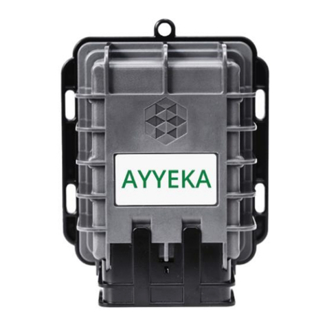
Ayyeka Wavelet User manual

QUICK START
GUIDE
BASIC
WAVELET
KIT
March 2019
P/N 0100585 RevA2
AYYEKA

3

IMPORTANT
Contact AYYEKA SUPPORTfor technical support:
support@ayyeka.com
+1(310) 876-8040 (US)
+3140 209-1001 (EMEA)
ALWAYS COORDINATEBasicWaveletKitinstallation with
the local authority before starting installation works,which
should be completed by trained and authorized personnel.
TheWARRANTY offeredbyAyyekacoversonlyAyyeka
supplied hardware and software for the duration of the
warranty period as per the warranty terms and conditions.
AYYEKAIS NOT LIABLE for damageor injury as aresult
of handling, installation, or maintenance of its supplied
systems.
DO NOT THROWAWAY the Basic WaveletKit,as itcontains
alithium battery. Pleasedisposeofproperly.
4G (LTE)/3G/2Gcellularnetwork signalis required for
proper communication.
OPERATING TEMPERATURERANGE of -40°C to
+80°C (-40°Fto+176°F).
1

SCHEMATIC
BOTTOM
Discrete Port
Cellular Antenna
Serial Port
Analog Port
17.4 cm (6.9in)
13.3cm
(5.2 in)
7.3cm
(2.8 in)
AYYEKA
2

3

GETTING STARTED
BASIC
WAVELETKIT
12
3
WaveletDevice&
Protector
M12 FieldAttachable
SensorConnectors
(optional;part WA00180,
ordered separately)
WaveletActivator
1x
1x1x
1x
1x
1x
4M8 FemaleFieldAttachable
PowerConnector
(optional;see page16)
1x
4

Other tools and/or materials maybe required (not included):
RotaryHammer Electric ScrewDriver
5Zip Ties, Screws,and
Anchors 6CellularAntenna
(REQUIRED; ordered separately)
4x2x 4x
5

NOTE: Special Installation Locations
WEAK SIGNAL LOCATIONS:
If the Waveletis installedin
an area with weakcellular
signal,activate the Wavelet
and place in the intended
installation location with
closeddoors/access hatch
(seestep3).
Login to
home.ayyeka.com to
ensure that cellular signal
has been recentlyupdated
in the last fewminutes.
UNDERGROUND/INDOOR
WAVELET INSTALLATIONS:
Before installation, initiate
the GPSoutside by
activating the Wavelet(see
step 3).
Waitfor at least 15minutes,
then log in to the user
interface at
home.ayyeka.com to
confirm updated location
on the map.
6

TURN HERE
DO NOT
TURN HERE
1Connectthe sensor cable(s)assembly withthe field
attachable connector tothe mating panel connector on the
Wavelet.Turnthe adjustable stainless steel end pieceto
securethe field attachable connector to the Wavelet.
CAUTION: Do not turn the blackplastic hood of the
connector. Turning the blackhood maycausethe wiresto
disconnect, break, and/or damage the connector pins.
SENSORCONNECTION
7

EXTERNALANTENNA CONNECTION
Connect the Cellular antennato the antenna port (ANT1).
2
AYYEKA
3Place the magnetic WaveletActivator on the embossed
Ayyekalogo on the frontofthe Waveletenclosure.Wavelet
will initiate a 15minute test mode of high frequency
sampling and transmission.The devicewill then return toits
default configuration.
8
IMPORTANT NOTE:
The antenna does not appear in the remaining depictions
in this guide, but should remain connected once properly
secured tothe appropriate panelconnectors.
Cellular Antenna
(required)

WAVELETACTIVATION
LED
Device Status
All
LEDs areoff
Not connected to network. The LED
lights do not blink when the device is
sampling.
Note: Waveletmay be powereddown(power
switchis inthe OFFposition), in
Hibernate mode,
or haveinsufficient battery power.
Green
-Red-Blue-Red-Green
LEDs
blink sequentially 5x Wavelet activated using Magnetic
Activator.
Green
LED is blinking Attempting to connect toGSM
network.
Green
LED remains on Transmission of data is in progress
via GSM; the LED will turn off when
transmission iscomplete.
Green
and Red LEDs blink 5x GSM communication error. The
device
failed totransmit.
4TheLEDlight on the back coverof the Waveletwillindicate
the devicestatus.
LED Status Indications
5Access the Ayyekauser interface at home.ayyeka.comusing
your log-in credentials. Expect data toappear
between 5 –10minutes after the test modeis initiated.
9

WAVELETACTIVATION
6Thescreendisplay should resemble the following:
If the Waveletis
transmitting properly,
you havecompleted the
installation successfullyand
canbegin collecting and
viewing your data!
If data does not transmit
properly, changethe
Waveletinstallation
location and activate again
(step3).If the problem
persists,contact Ayyekafor
assistance.
support@ayyeka.com
+1(310) 876-8040 (US)
+3140 209-1001(EMEA)
10

CAUTION: Theprotector is provided to shield the
connector from tampering or overexposure that could
result in disconnected wiring.
LowerClips
11
7After the Waveletcompletes the transmission process,place
the Waveletprotector above the connector ports andsecure
the Waveletprotector into the Waveletenclosure.
Upper Clips
a
a. Insert the two lower clips into the two lower holes of the
Waveletenclosure.
b. Snapthe upper clips into placein the two grooves above
the panel connector.
b

8Securethe Waveleton a wall,pipe, orother secure
mounting location using zipties orscrews.
OR
Wall
Mounted
Pipe
Mounted
12

YOUR BASIC WAVELET KIT
IS NOW SUCCESSFULLY
INSTALLED!
13

WAVELETPINOUT
C
onnect
or
Pin
#
Function
Description Cable Connector
Pin Assignment
1
Signal
4-20mA or 0-27.5VInput #1 Front Back
2
Common
Negative(-)
3
Supply+
Wavelet12V PowerSupply #2(+)
4
Supply+
Wavelet12V PowerSupply #1(+)
5
Signal
4-20mA or 0-27.5VInput #4
6
Signal
4-20mA or 0-27.5VInput #3
7
Signal
4-20mA or 0-27.5VInput #2
8
Common
Negative(-)
#4
14
#3
#1 #2
ANALOG –PANELCONNECTOR#1 –M12 8-PIN MALE

WAVELETPINOUT
DISCRETE–PANELCONNECTOR#3 –M12 5-PINMALE
POWER–PANELCONNECTOR#4 –M8 3-PINMALE
Connector
Pin
#
Function
Description
Cable Connector
Pin
Assignment
1
Signal
Pulse Counter/Digital Input
#0
Front Back
2
Common
Negative(-)
3
Signal
Pulse Counter/Digital Input
#1
4
Common
Negative(-)
5
Signal
Digital Input/Output (DIO)
Connector
Pin
#
Function
Description
Cable Connector
Pin
Assignment
1
Supply+
5-28VDC(+) Front Back
3
No
Signal No Connection
4
Common
Negative(-)
SERIAL–PANELCONNECTOR#2 –M12 8-PINFEMALE
Connector
Pin
#
Function
Description
Cable Connector
Pin
Assignment
1
Signal RS232 TX Front Back
2
Supply+ Wavelet12V PowerSupply #4(+)
3
Supply+ Wavelet12V PowerSupply #3(+)
4
Signal SDI-12
5
Signal RS485 B
6
Signal RS485 A
7
Signal RS232 RX
8
Common Negative(-)
15
12
34
5

M8 3-Pin Female
PowerConnector
+Installation Tool
for WireTermination
(Included)
No
Connection
POWERCONNECTOR PINOUT
If usingan external power source,refer tothe pinout below:
EXTERNAL POWER:
44
Negative (-)
16
3311
5-28VDC (+)
Wire To Connect:
Cable Wire Cross 0.14 –0.5 mm2
Selection Surface Area
Wire Gauge AWG 26-20
Cable Ø Diameter 4 –5.5 mm

NOTES
17
Other manuals for Wavelet
1
Table of contents
Other Ayyeka Measuring Instrument manuals