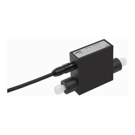
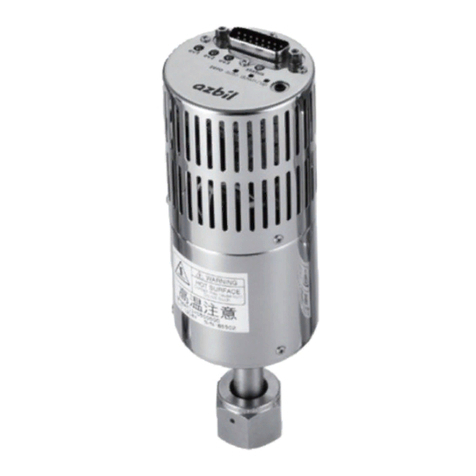
Azbil Micro Flow CMS9500 User manual

Thank you for purchasing an Azbil
Corporation product.
This manual contains information
for ensuring the correct use of this
product. It also provides necessary
information for installation, main-
tenance, and troubleshooting.
This manual should be read by
those who design and maintain
equipment that uses this product.
Be sure to keep this manual nearby
for handy reference.
Gas Mass Flow Meter
SUS/SUS316 Models
CMS9500/0002/0005/
0020/0050/0200/0500
User's Manual
No. CP-SP-1189E
TM

Please read“Terms and Conditions”from the following URL
before ordering and use.
https://www.azbil.com/products/factory/order.html
NOTICE
Be sure that the user receives this manual before the product is used.
Copying or duplicating this user’s manual in part or in whole is forbidden.
The information and specifications in this manual are subject to change
without notice.
Considerable effort has been made to ensure that this manual is free from
inaccuracies and omissions. If you should find an error or omission, please
contact the azbil Group.
In no event is Azbil Corporation liable to anyone for any indirect, special or
consequential damages as a result of using this product.
© 2006-2019 Azbil Corporation. All Rights Reserved.
µFTM, Micro FlowTM are trademarks of Azbil Corporation in Japan.

i
Conventions Used in This Manual
To prevent injury to the operator and others, and to prevent property damage, the
following types of safety precautions are indicated:
In describing the product, this manual uses the icons and conventions listed below.
Use caution when handling the product.
The indicated action is prohibited.
Be sure to follow the indicated instructions.
Handling Precautions:
Handling Precautions indicate items that the user should pay attention to
when handling the Gas Mass Flow Meter.
Note: Notes indicate information that might benefit the user.
This indicates the item or page that the user is requested to refer to.
(1), (2), (3): Numbers within parentheses indicate steps in a sequence or parts of an
explanation.
03 P07 This font is used to indicate output on the 7-segment display.
[XXXX] key: This indicates keys on the control panel.
WARNING Warnings are indicated when mishandling this product might
result in death or serious injury.
CAUTION
Cautions are indicated when mishandling this product might result
in minor injury to the user, or physical damage to the product.

ii
WARNING
When using a combustible gas, install the device upstream of the safety shutoff valve.
If air or oxygen somehow enters the piping, resulting in an explosive mixture, and the
sensor makes a spark due to some cause like a lightning strike, an explosion could
occur inside the pipe.
Never allow combustible gases (especially gases that are within explosive limits) to
pass through this device. Doing so might result in an explosion.
If a model designed for use with oxygen has been used for other gases, do not use it
again for oxygen.
Doing so could cause a serious accident.
If a model not designed for use with oxygen has been purchased, do not use it for oxy-
gen. Doing so could cause a serious accident.
CAUTION
Check the product connections and pipe connections for leakage before use.
Also, check the connections for leakage regularly after the start of use.
It is the user’s responsibility to ensure that gas leaks can be reliably detected. This is
especially important if a dangerous gas is used.
Be sure to use this device within the flow-rate range stipulated in the product specifi-
cations.
To prevent excessive flow, use a suitable means to control the supply pressure or use a
throttle valve or the like to control the flow rate. If the flow rate exceeds the high limit,
both the flow rate display and the output voltage/current may indicate considerably
lower values than the actual flow rate.
Behavior when the flow rate greatly exceeds the measurement range (P.7)
If loss or damage could result from the abnormal functioning of this device, include
appropriate redundancy in the system design.
Prevent foreign matter from entering this device.
If rust, water droplets, oil mist, dust, etc. from the pipes enters the device, measure-
ment error might occur or this device may be damaged.
If there is a possibility of foreign matter entering the device, install an upstream filter,
strainer, or mist trap capable of eliminating foreign matter 1 µm or greater in diameter.
Be sure to inspect and replace the filter at regular intervals.
If this device is used to monitor gas flow rate to a burner, design pipes and instrumen-
tation so that backfire will not damage the device.
This device is a precision instrument. Do not drop it or subject it to shock. Doing so
might damage the device.
Do not use this device outside of the operating pressure range. Also, do not subject it
to pressure beyond the rated pressure resistance range. Doing so might damage it.
When making the pipe connections, fix the flange section of the pipe connector port
in place, and turn the pipe to tighten.
Safety Precautions

iii
CAUTION
When installing, fasten firmly to prevent vibration.
If using Rc connections, take care not to coat with too much sealant. Foreign mat-
ter or burrs in the pipes may cause measurement error.
Before connecting pipes with Swagelok or VCR connections, check the instructions in
the manual provided by the connecting joint manufacturer.
When purchasing a connecting joint, use the following made by Swagelok Co., Ltd:
SS-400-1-6STSC11 1/4 Swagelok,
SS-810-1-8STSC11 1/2 Swagelok,
SS-4-VCR-1-00032SC11 1/4 VCR,
SS-8-VCR-1-8STSC11 1/2 VCR, or equivalent.
Observe the following when using this flowmeter for oxygen gas:
• Piping work should be done by a specialist experienced in handling oxygen gas,
observing the general precautions related to oxygen gas.
• Use degreased pipes and parts.
• Be sure to remove foreign matter, burrs, etc., from the pipes before connecting
this flowmeter.
When carrying or installing this device, never hold it by the resin cover.
Doing so could damage the cover, or the device could slip and fall, causing an injury.
Mount this device horizontally.
If it is mounted vertically, drift may occur when the flow rate is zero, resulting in an
erroneous measurement.
Do not mount with the top surface facing down.
Doing so might cause measurement error or device failure.
When using a relay as the contact for totalized flow count reset input, use a relay
designed for minute currents (with gold contacts).
Failure to do so could cause faulty contact, resulting in malfunction.
If there is a risk of a power surge caused by lightning, use a surge absorber (surge pro-
tector). Failure to do so might cause fire or device failure.
Check that the wiring is correct before turning the power on.
Incorrect wiring can cause damage or malfunction.
Do not operate the control panel keys using a sharp object such as a mechanical pen-
cil or screwdriver. Doing so could cause damage.
Do not remove the resin cover and disassemble the piping connector part. Doing so
could cause damage.
Make sure that the selected analog output type matches the input type of the receiv-
ing device. The receiving device could be damaged if the analog output type selection
is incorrect.

iv
The Role of This Manual
There are two different manuals related to SUS/SUS316 models of CMS/CMF High-Flow
Mass Flow Meters. Read them as necessary for your specific requirements.
If a manual you require is not available, contact the azbil Group or its dealer.
Gas Mass Flow Meter SUS/SUS316 Models CMS 9500/0002/0005/
0020/0050/0200/0500 User's Manual
Document No. CP-UM-1189E
This manual.
This manual is supplied with the product.
Personnel in charge of the design or configuration of equipment that
incorporates this device should read this manual thoroughly.
The manual covers safety precautions, installation, wiring, troubleshoot-
ing, and primary specifications.
Gas Mass Flow Meter User's Manual for Communication
Functions Document No. CP-SP-1184E
Personnel who use this device's communications functions should
read this manual.
The manual gives an overview of communications, describes wir-
ing, transmission protocols, communications data, and trouble-
shooting, and gives communications specifications.

v
Contents
Conventions Used in This Manual
Safety Precautions
The Role of This Manual
Chapter 1. Overview
Overview..................................................1
Features...................................................1
Model selection guide......................................2
Chapter 2. Names and Functions of Parts
Chapter 3. Mounting and Wiring
Installation ................................................7
Behavior when the flow rate greatly exceeds the measurement range
. 7
Piping.....................................................8
Installing the flowmeter.................................. 11
Wiring .................................................. 13
Chapter 4. Operation
State transition .......................................... 16
Function setup .......................................... 17
Parameter setup ......................................... 21
Display OFF mode ....................................... 24
Totalized flow and reverse-totalized flow.................. 24
Memory backup for totalized flow and reverse-totalized flow
24
How to reset the totalized flow and reverse-totalized flow .. 24
Event standby ........................................... 24
Event ON-delay .......................................... 25
Zero flow rate calibration................................. 25
Chapter 5. Troubleshooting
Countermeasures for abnormal operation ................. 26
Chapter 6. Specifications
General specifications.................................... 28
Korea certification mark.................................. 33
External dimensions ..................................... 34
Pressure loss ............................................ 40


1
Overview
SUS/SUS316 models of CMS 9500/0002/0005/0020/0050/0200/0500
Gas Mass Flow Meters measure mass flow by means of a Micro Flow
thermal mass flow sensor (hereafter, μF sensor) developed by Azbil
Corporation
Integrating the µF sensor with advanced channel design technology
has achieved high accuracy and high rangeability.
Features
• The CMS incorporates μF sensors made with silicon micromachin-
ing and thin-film technology.
The µF sensor is a highly sensitive flow speed sensor with fast
response. Each of its sides is only 1.7 mm long, and it is just 0.5 mm
thick.
• Because the CMS is a mass flowmeter, its measurements are not
affected by temperature or pressure.
• Provides high accuracy (±3 % rdg.*) and high rangeability (100:1).
Model Measurement range
CMS9500 5–500 mL/min (standard)
CMS0002 0.02–2 L/min (standard)
CMS0005 0.05–5 L/min (standard)
CMS0020 0.2–20 L/min (standard)
CMS0050 0.5–50 L/min (standard)
CMS0200 2–200 L/min (standard)
CMS0500 5–500 L/min (standard)
* "Rdg." (reading ) is the value indicated by the device.
Chapter 6. Specifications (P. 28).
• To meet a variety of requirements, the CMS's functions include
analog output, event output, totalized/reverse-totalized flow display,
output scaling, gas type selection, totalizer pulse output, external
contact input (totalized flow count reset input), serial data output,
etc.
• Straight pipe sections are not required before and after this device
(if the device and the pipes have the same pipe size).
Chapter 1. Overview

2
Chapter 1. Overview
Model selection guide
zSUS model Example: CMS9500BSRN200000
Basic
model
No.
Flow
rate
range
Model
Gas-con-
tacting
material
Con-
nection
method
Gas
type
Out-
put
Option
1
Option
2
Option
3
Option
4
Appended
No.
Description
CMS Gas mass ow meter
9500 0–500 mL/min (standard)*1*4
0002 0–2 L/min (standard)*1*4
0005 0–5 L/min (standard)*1 *4
0020 0–20 L/min (standard)*1*4
0050 0–50 L/min (standard)*1*4
0200 0–200 L/min (standard)*1*4
0500 0–500 L/min (standard)*1*4
B With display (ow direction: left to right)
R With display (ow direction: right to left)
S SUS303
R
Rc connection (for short face-to-face dimension),
CMS0200/0500: Rc 1/2,
CMS9500/0002/0005/0020/0050: Rc 1/4
N Air/nitrogen*2
S Oxygen*3*5
2 0–5 V DC / 1–5 V DC / 4–20 mA
0 No optional functions
1 Degreasing for gas-contacting parts*5
0 No optional functions
D With inspection report
Y With traceability certicate
0 Product version
*1. mL/m in (standard) and L/min (standard) indicate the volumetric ow rate per minute converted to conditions of 20 °C and
101.325 kPa (1 atm).
The reference temperature can be changed in a range from 0 to 35 °C (in 1 °C increments).
*2. The model is set for air/nitrogen use before shipment.
The gas type can be changed to argon, carbon dioxide (CO2), fuel gas 13A (LNG, either 45 or 46 MJ/m3), 100 % propane, 100 %
methane, or 100 % butane.
*3. The model is set for oxygen use before shipment.
The gas type can be changed to air/nitrogen, argon, carbon dioxide (CO2), fuel gas 13A (LNG, either 45 or 46 MJ/m3), 100 %
propane, 100 % methane, or 100 % butane.
Never change the setting back to oxygen if the CMS has been used even once for any other gas.
*4. The ow rate ranges shown in the above table are for air.
The measurable ow rate range varies depending on the gas type.
For details, see Maximum measurable ow rate and output voltage for various gas types (P. 32).
*5. If oxygen is selected as the gas type, “1” (degreasing for gas-contacting parts) must be selected for option 3.

3
Chapter 1. Overview
zSUS 316 model
Basic
model
No.
Flow
rate
range
Model
Gas-con-
tacting
material
Con-
nection
method
Gas
type
Out-
put
Op-
tion 1
Op-
tion 2
Op-
tion 3
Op-
tion 4
Ap-
pend-
ed No.
Description
CMS Gas mass ow meter
9500 0–500 mL/min (standard)*1*4
0002 0–2 L/min (standard)*1*4
0005 0–5 L/min (standard)*1*4
0020 0–20 L/min (standard)*1*4
0050 0–50 L/min (standard)*1*4
0200 0–200 L/min (standard)*1*4
0500 0–500 L/min (standard)*1*4
B With display (ow direction: left to right)
R With display (ow direction: right to left)
T SUS316
UUNF connection, CMS0200/0500: 3/4-16 UNF
CMS9500/0002/0005/0020/0050: 9/16-18 UNF
T
Rc connection,
CMS0200/0500: Rc 1/2,
CMS9500/0002/0005/0020/0050: Rc 1/4
S
Swagelok connection,
CMS0200/0500: 1/2 Swagelok
CMS9500/0002/0005/0020/0050: 1/4 Swagelok
V
VCR connection,
CMS0200/0500: 1/2 VCR
CMS9500/0002/0005/0020/0050: 1/4 VCR
N Air/nitrogen*2
S Oxygen*3*5
2 Analog output: 0–5 V DC / 1–5 V DC / 4–20 mA
0 No optional functions
1 With RS-485 communications
0 No optional functions
0 No degreasing
1 Degreasing for gas-contacting parts*5
0 No optional functions
D With inspection report
Y With traceability certificate
0 Product version
*1. mL/m in (standard) and L/min (standard) indicate the volumetric ow rate per minute converted to conditions of 20 °C and
101.325 kPa (1 atm).
The reference temperature can be changed in a range from 0 to 35 °C (in 1 °C increments).
*2. The model is set for air/nitrogen use before shipment.
The gas type can be changed to argon, carbon dioxide (CO2), fuel gas 13A (LNG, either 45 or 46 MJ/m3), 100 % propane, 100 %
methane, or 100 % butane.
*3. The model is set for oxygen use before shipment.
The gas type can be changed to air/nitrogen, argon, carbon dioxide (CO2), fuel gas 13A (LNG, either 45 or 46 MJ/m3), 100 %
propane, 100 % methane, or 100 % butane.
Never change the setting back to oxygen if the CMS has been used even once for any other gas.
*4. The ow rate ranges shown in the above table are for air.
The measurable ow rate range varies depending on the gas type.
For details, see Maximum measurable ow rate and output voltage for various gas types (P. 32).
*5. If oxygen is selected as the gas type, “1” (degreasing for gas-contacting parts) must be selected for option 3.

4
Chapter 1. Overview
zOptional parts (sold separately)
Product Model No. Description
Harness with dedicated
connector (One harness is
required for one CMS unit.)
81446594-005 For non-communication models, 2 m harness (8-core)
without crimp terminals
81446594-006 For non-communication models, 5 m harness (8-core)
without crimp terminals
81446594-007 For communication models, 2 m harness (10-core)
with M3.5 spade terminals
81446594-008 For communication models, 5 m harness (10-core)
with M3.5 spade terminals
Mounting bracket 81446628-001 For CMS9500/0002/0005/0020/0050
81446721-001 For CMS0200
81446856-001 For CMS0500
AC adapter 81446957-001 Operating temperature: 0 to 40 °C
AC adapter connection harness
81446594-030 Necessary when the AC adapter is used
zReplacement parts
Product Model No. Description
Replacement ttings (for
SUS316 models only)
81446834-001 Two Rc 1/4 ttings
81446834-002 Two Rc 1/2 ttings
81446833-001 Two 1/4 Swagelok ttings
81446833-002 Two 1/2 Swagelok ttings
81446895-001 Two 1/4 VCR ttings
81446895-002 Two 1/2 VCR ttings

5
[ENT] key:
Used to save the setting.
[MODE] key:
Used to switch the mode to setup mode.
Outlet pipe connection port:
Gas ow outlet
Resin cover
Flange
Signal connector:
Connects the power
and also the output signals.
Inlet pipe connection port:
Gas ow inlet
Flow rate display:
Shows the ow rate using a 4-digit 7-segment LED.
During setup, the rst two digits and the last two
digits show the function and the setting respectively.
EV1 and EV2 indicators:
Lit when event output is generated.
Display unit
Instantaneous ow
rate indicator:
Lit when the instantaneous
ow rate is displayed.
Totalized ow indicator:
Lit while the totalized
ow is displayed.
[DISP] key:
Used to switch to a dierent display.
Mass Flow Meter
X10L
L/min
EV2
EV1
ENTMODEDISP
[ ] and [ ] keys:
Used to select modes and settings.
Chapter 2.
Names and Functions of Parts

6
WARNING
When using combustible gas, install the device upstream of the safety shutoff valve. If air somehow
enters the piping, resulting in an explosive mixture, and the sensor makes a spark due to some
cause like a lightning strike, an explosion could occur inside the pipe.
Never allow a gas that is within explosive limits to pass through this device.
Doing so might result in an explosion.
If a model designed for use with oxygen has been used for other gases, do not use it again for
oxygen. Doing so could cause a serious accident.
If a model not designed for use with oxygen has been purchased, do not use it for oxygen.
Doing so could cause a serious accident.
CAUTION
Check the product connections and pipe connections for leakage before use.
Also, check the connections for leakage regularly after the start of use.
It is the user’s responsibility to ensure that gas leaks can be reliably detected. This is especially
important if a dangerous gas is used.
Be sure to use this device within the flow-rate range stipulated in the product specifications.
To prevent excessive flow, use a suitable means to control the supply pressure or use a throttle
valve or the like to control the flow rate. If the flow rate exceeds the high limit, both the flow
rate display and the output voltage/current may indicate considerably lower values than the
actual flow rate.
"Behavior when the flow rate greatly exceeds the measurement range" (page 7)
If loss or damage could result from the abnormal functioning of this device, include appropri-
ate redundancy in the system design.
Prevent foreign matter from entering this device.
If rust, water droplets, oil mist, dust, etc. from the pipes enters the device, measurement error
might occur or this device may be damaged.
If there is a possibility of foreign matter entering the device, install an upstream filter, strainer,
or mist trap capable of eliminating foreign matter 1 µm or greater in diameter. Be sure to
inspect and replace the filter at regular intervals.
If this device is used to monitor gas flow rate to a burner, design pipes and instrumentation so
that backfire will not damage the device.
This device is a precision instrument. Do not drop it or subject it to shock. Doing so might
damage the device.
Do not use this device outside of the operating pressure range. Also, do not subject it to pres-
sure beyond the rated pressure resistance range. Doing so might damage it.
When making the pipe connections, fix the flange section of the pipe connector port in place,
and turn the pipe to tighten.
When installing, fasten firmly to prevent vibration.
If using Rc connections, take care not to coat with too much sealant. Foreign matter or burrs in
the pipes may cause measurement error.
Before connecting pipes with Swagelok or VCR connections, check the instructions in the
manual provided by the fitting manufacturer.
When purchasing a fitting, use the following or an equivalent:
1/4 Swagelok: SS-400-1-6STSC11
1/2 Swagelok: SS-810-1-8STSC11
1/4 VCR: SS-4-VCR-1-00032SC11
1/2 VCR: SS-8-VCR-1-8STSC11, or equivalent.
Chapter 3. Mounting and Wiring

7
Chapter 3. Mounting and Wiring
CAUTION
Observe the following when using this flowmeter for oxygen gas:
• Piping should be done by a specialist experienced in handling oxygen gas, observing
general precautions related to oxygen gas.
• Use degreased pipes and parts.
• Be sure to remove foreign matter, burrs, etc. from the pipes before connecting this flow-
meter.
Do not remove the resin cover and disassemble the piping connector part. Doing so could
cause damage.
When carrying or installing this device, never hold it by the resin cover.
Doing so could damage the cover, or the device could slip and fall, causing an injury.
Installation
zInstallation location
Avoid installing the device where it will be subject to conditions such
as the following.
• Ambient temperature colder than -10 ˚C or hotter than 60 °C
• Humidity higher than 90 % RH
• Sudden temperature fluctuations causing dew condensation
• Corrosive gas or flammable gas atmosphere
• Large amounts of dust, salt, iron powder or other conductive sub-
stances, water droplets, oil mist, or organic solvents
• Direct vibration or shock
• Direct sunlight
• Water or rain
• Splashing by fluids (e.g. oil, chemicals)
• Strong magnetic or electrical field
Behavior when the flow rate greatly exceeds the measurement range
If the flow rate exceeds the high limit for measurement, the cor-
rect value may not be displayed or output. Be sure to use the device
within the measurement range stated in the specifications.
If the flow rate exceeds 120 % of the high limit, the display alternately
shows the flow rate and ALH1. If the flow rate increases further, the
display does not show ALH1, but shows lower values than the actual
flow rate. Note that if the flow rate suddenly becomes excessive, ALH1
may not be displayed. Especially when this device is used for flow
control, make sure to take appropriate measures, such as controlling
the supply pressure or using a throttle valve, so that even at maxi-
mum control output (100 %), the flow rate does not exceed 120 % of
the high limit of the range.
Flow rate
Flow rate
indication Flow rate indication
Flow rate indication
High limit
120 % of high limit
Display
Flow rate
range
Flow rate and ALH 1
alternately

8
Chapter 3. Mounting and Wiring
Piping
zPrecautions for piping work
This device is a precision instrument. If even a small amount of
foreign matter like dust, moisture, or oil mist enters the device, mea-
surement error or device failure may result.
During piping work, follow the instructions below to keep foreign
matter out of the device.
(1) Before installing the device, thoroughly flush the inside of piping
that is upstream and downstream of this device to remove weld-
ing fumes and dust.
(2) Thoroughly clean the inside of piping that is directly connected to
the device.
(3) After steps (1) and (2), make sure that there are no welding fumes
and dust before installation.
Handling Precautions
• If foreign matter cannot be fully eliminated by flushing or
wiping, or if the regular presence of foreign matter can be
expected, be sure to install a filter. If dust, oil or moisture adheres
to the metallic mesh or to the Micro Flow sensor chip, measure-
ment error or device failure may result.
zFilter installation
• For a dedicated filter, contact the azbil Group.
• For applications with compressed air or propane, which regularly
contain oil mist, or applications where rust in the piping is expect-
ed, be sure to install a filter. Recommended type:
Name : MFF200NAG
Specifications: Azbil Corporation specifications sheet CP-SS-
1824E.
Restrictor
Flow direction
μF sensor
Metallic mesh
Spacers

9
Chapter 3. Mounting and Wiring
zStraight pipe length
If the flowmeter and the pipe have different internal diameters (diameters A and B
are different), a straight pipe section is required.
CMS CMS
B B
5D
A A
B B
5D 3D
3D
AA
CMS CMS
Upstream expansion Downstream reduction
Dierent diameter socket, etc. Dierent diameter socket, etc.
D represents the connecting port size.
CMS0200/0500: 12 mm
CMS9500/0002/0005/0020/0050: 6 mm
CMS CMS
5D
B
BB
5D 3D
3D
AA
BAA
CMS CMS
Upstream reduction Downstream expansion
Dierent diameter socket, etc. Dierent diameter socket, etc.
If the flowmeter and the pipe have the same internal diameter (diameters A and B
are the same), a straight pipe section is not required.
CMS CMS
A
B
B
CMS CMS
BA B A
Upstream elbow Downstream elbow
Upstream ball valve, etc.
(ow is not disturbed)
Downstream ball valve, etc.
(ow is not disturbed)
A
Handling Precautions
• If a valve like a butterfly valve disturbs the flow, provide a
straight pipe section whose length is five times the pipe
diameter between the flowmeter and the valve.

10
Chapter 3. Mounting and Wiring
zRc connection
• Coating sealant
Coat the pipe threads, except the two nearest the tip, with an appro-
priate amount of sealant.
Remove dirt or burrs from the inside of the pipe.
Right Wrong
Sealant Sealant
• Piping connection
When connecting the piping, hold the flowmeter by putting a
wrench on the flange.
Flange
Resin cover
Body
Pipe
zUNF connection
• Fitting connection
When connecting a fitting, hold the flowmeter by putting a wrench
on the flange.
Handling Precautions
• Do not grip and turn the
main part of the device.
Doing so might cause
damage or leakage.
• When connecting the pip-
ing, do not hold the flow-
meter by the resin cover.
Doing so might damage
the cover.
• Observe the specified
tightening torque.
zGas flow
Handling Precautions
• Gas must flow through the meter in the direc-
tion of the arrow on the side of the flow chan-
nel. Flow in the opposite direction cannot be
measured accurately.
Fitting
Tightening torque
CMS9500/0002/0005/0020/0050: 40 to 45 N•m
CMS0200/0500: 50 to 60 N•m
Resin cover
Flange
Body
Gas Gas

11
Chapter 3. Mounting and Wiring
Installing the flowmeter
CAUTION
Mount this device horizontally.
If it is mounted vertically, drift may occur when the flow rate is zero, resulting in an
erroneous measurement.
Do not mount with the top surface facing down.
Doing so might cause measurement error or device failure.
zMounting orientation
zInstallation
There are two methods of mounting the flowmeter:
(1) Attach the flowmeter using the mounting screw holes on the bot-
tom, working from the bottom of the device. Two or four screws
are used depending on the model.
Massflow
X10L
L/min
EV2
EV1
ENTMODEDISP
RIGHT
RIGHT
WRONG
Hole dimensions when mounted directly
Unit: mm
48
27
4.5
48
15
4.5
80
30
5.5
CMS9500/0002/0005/0020/0050
CMS0200
CMS0500

12
Chapter 3. Mounting and Wiring
(2) Mount the flowmeter on the dedicated mounting bracket, and
then attach the bracket with four screws from the top of the
bracket. Mounting bracket model number
81446628-001: For CMS9500/0002/0005/0020/0050
81446721-001: For CMS0200
81446856-001: For CMS0500
Mounting bracket
63
78
4.5
48
58
4.5
Hole dimensions when mounting bracket is used
75
80
5.5
Unit: mm
CMS9500/0002/0005/0020/0050
CMS0200
CMS0500
This manual suits for next models
6
Table of contents
Other Azbil Measuring Instrument manuals

Azbil
Azbil MCB10A User manual

Azbil
Azbil SR100 User manual

Azbil
Azbil NWA300 User manual

Azbil
Azbil AUR355 User manual

Azbil
Azbil mF CMG Series User manual

Azbil
Azbil SPG Series User manual

Azbil
Azbil CML 050 User manual

Azbil
Azbil MCF0080 User manual

Azbil
Azbil MVF Series User manual

Azbil
Azbil mF MVF Series User manual

Azbil
Azbil SR Series User manual

Azbil
Azbil mF MCF User manual

Azbil
Azbil MCW400A100 User manual

Azbil
Azbil MVC10A User manual

Azbil
Azbil MagneW Plus+ Series User manual

Azbil
Azbil MagneW Two-wire PLUS+ MTG15A User manual

Azbil
Azbil MagneW FLEX+ User manual

Azbil
Azbil 700 series User manual

Azbil
Azbil V8 User manual

Azbil
Azbil MCF Series User manual