Toc-1
IM 12E01A06-02E
<CONTENTS>
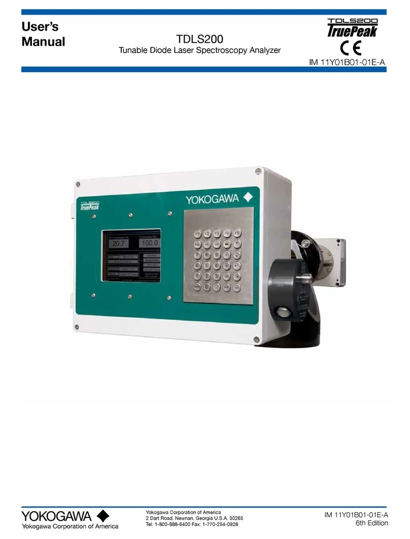
Model TB750G
Right Angle Scattered Light Turbidimeter Quick Start Manual
CONTENTS
IM 12E01A06-02E 3rd Edition
INTRODUCTION .......................................................................................................i
Symbol and Notations Used in this Manual ................................................................. i
Notice ............................................................................................................................... ii
1. OVERVIEW ................................................................................................ 1-1
1.1 Features ............................................................................................................. 1-1
1.2 Measurement Principle .................................................................................... 1-1
2. PIPING AND WIRING ................................................................................ 2-1
2.1 Piping ................................................................................................................. 2-1
2.1.1 System Using Open Head Tank and Zero Turbidity Filter ................. 2-1
2.1.2 System without Head Tank and Zero Turbidity Filter ......................... 2-2
2.2 Wiring ................................................................................................................. 2-3
2.2.1 Wiring Required for TB750G ............................................................. 2-3
2.2.2 Wiring for Detector ............................................................................. 2-4
2.2.3 Wiring for Converter........................................................................... 2-5
3. OPERATION .............................................................................................. 3-1
3.1 Preparation ........................................................................................................ 3-1
3.1.1 Outline................................................................................................ 3-1
3.1.2 Converter Operation Panel ................................................................ 3-1
3.1.3 Calibration.......................................................................................... 3-2
3.1.4 Performing Zero/span Calibration Using Filtered Water as Zero Reference
3-3
3.1.5 Performing 2-point Calibration Using Standard Solution................... 3-7
3.2 Normal Operation.............................................................................................. 3-8
3.2.1 When Sample Water Supply is Cut Off.............................................. 3-8
3.2.2 Shutdown ........................................................................................... 3-8
3.2.3 Restart................................................................................................ 3-8
4. PARAMETER SETTING............................................................................ 4-1
4.1 Outline of Operation, Setting, and Service Levels ........................................ 4-1
4.2 Operation Level................................................................................................. 4-2
4.3 Setting Level...................................................................................................... 4-3
4.4 Service Level ..................................................................................................... 4-4
4.5 Procedures for Setting Parameters ................................................................ 4-6
