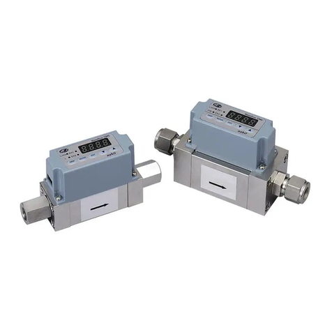
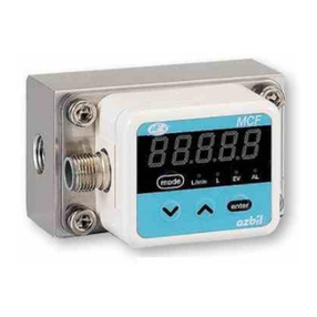
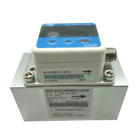
Azbil mF MCF User manual

MCF
Air Flowmeter
User's Manual
for
Communication Functions
No. CP-SP-1300E
TM
Thank you for purchasing the MCF Air
Flowmeter.
This manual contains information for
ensuring the correct use of the MCF. It
also provides necessary information for
installation, maintenance, and trou-
bleshooting.
This manual should be read by those
who design and maintain equipment
that uses the MCF. Be sure to keep this
manual nearby for handy reference.

The µFTM, Micro Flow and µF sensor are trademarks of Azbil Corporation in
Japan.
If it is necessary to change the parameters of the MCF flowmeter frequently by
communications, write the changes to RAM, not to EEPROM. EEPROM is limited to
10,000 erase/write cycles.
Note that data in RAM is cleared and replaced with data from EEPROM if the power
supply to the MCF is interrupted.
IMPORTANT
©2009-2012 Azbil Corporation All Rights Reserved.
Be sure that the user receives this manual before the product is used.
Copying or duplicating this user’s manual in part or in whole is forbid-
den. The information and specifications in this manual are subject to
change without notice.
Considerable effort has been made to ensure that this manual is free
from inaccuracies and omissions. If you should find an error or omis-
sion, please contact the azbil Group.
In no event is Azbil Corporation liable to anyone for any indirect, special
or consequential damages as a result of using this product.
NOTICE

Conventions Used in This Manual
i
■To prevent injury to the operator and others, and to prevent property damage, the following types of safety
precautions are indicated:
■In describing the product, this manual uses the icons and conventions listed below.
Use caution when handling the product.
The indicated action is prohibited.
Be sure to follow the indicated instructions.
Handling Precautions:
Handling Precautions indicate items that the user should pay attention to when
handling the MCF.
Note:Notes indicate information that might benefit the user.
:This indicates the item or page that the user is requested to refer to.
(1), (2), (3): Numbers within parentheses indicate steps in a sequence or parts of an
explanation.
>>: Indicates the result of an operation, details displayed on the personal computer or
other devices, or the state of the device after operation.
03、P-07 This indicates 7-segment indication on the setup display.
[MODE] key:This indicates a key on the setup display.
WARNING Warnings are indicated when mishandling this product might result in
death or serious injury.
CAUTION Cautions are indicated when mishandling this product might result in
minor injury to the user, or only physical damage to the product.

ii
Safety Precautions
CAUTION
Before removing, mounting, or wiring the MCF, be sure to turn off the MCF and all con-
nected devices. Failure to do so might cause electric shock.
Do not disassemble the MCF.
Doing so might cause malfunction.
Wire this device properly, according to the standards given in this document, using the
specified types of wire and connection procedures. Failure to do so could result in mal-
function.
Use this device within the operating ranges given in the specifications for temperature,
humidity, voltage, vibration, shock, mounting direction, atmosphere, etc. Failure to do
so might cause malfunction.
Do not allow wire clippings, metal shavings, water, etc. to enter the device’s case. If
they do, they could cause faulty operation or device failure.

The Role of This Manual
iii
MCF Air Flowmeter User's Manual for Communication Functions
Manual No. CP-SP-1300E
This manual.
Those using the "communication functions" of the MCF series should read
this manual.
This manual describes an outline of communications, wiring, communication
procedures, a list of MCF series communication data, how to remedy
trouble, and communication specifications.
U
ser'sM
anual
C
P-UM-0
1
2
3E
WARNING
C
AUTI
O
N
WARNING
C
AUTI
ON
MCF Air Flowmeter User's Manual for Installation
Manual No. CP-UM-5498JE
This manual is supplied with the device. Personnel in charge of design and/or
manufacture of a system using this device must thoroughly read this manual.
This manual describes the safety precautions, installation, wiring, list of
parameters, and primary specifications.
MCF Air Flowmeter User's Manual for Installation and Configuration
Manual No. CP-SP-1276E
The manual describes the hardware and all functions of this device.
Personnel in charge of design, manufacture, operation, and/or maintenance
of a system using this device must thoroughly read this manual. It describes
installation, wiring, functions and settings, operating procedures, trou-
bleshooting, and specifications.
A total of three different manuals are available for the MCF. Read them as necessary for your specific requirements.
If a manual you require is not available, contact the azbil Group or its dealer.

Organization of This User's Manual
iv
This manual is organized as follows:
Chapter 1. OVERVIEW
This chapter describes communication outline of the MCF series.
Chapter 2. WIRING
This chapter describes RS-485 wiring methods to make a communication
link between the MCF series and other instruments.
Chapter 3. SETTING
This chapter describes MCF series communication settings.
Chapter 4. COMMUNICATION PROCEDURE
This chapter describes communication procedures, message configuration,
data read/write and signal timing operations.
Chapter 5. COMMUNICATION DATA TABLE
This chapter provides various data address tables for communications on
the MCF series.
Chapter 6. TROUBLESHOOTING
This chapter describes checkpoints to diagnose failures in MCF series com-
munications.
Chapter 7. SPECIFICATIONS
This chapter lists communication specifications for the MCF series.
Appendix
The appendix provides code table.

Contents
v
Conventions Used in This Manual
Safety Precautions
The Role of This Manual
Organization of This User's Manual
Chapter 1. OVERVIEW
■Features •••••••••••••••••••••••••••••••••••••••••••••••••••••••••••••••1-1
■Hardware configuration 1 ••••••••••••••••••••••••••••••••••••••••••••••1-1
■Hardware configuration 2 ••••••••••••••••••••••••••••••••••••••••••••••1-2
Chapter 2. WIRING
■Connection with 3-wire system ••••••••••••••••••••••••••••••••••••••••2-2
■Connection with 5-wire system ••••••••••••••••••••••••••••••••••••••••2-3
Chapter 3. SETTING
■Setting method•••••••••••••••••••••••••••••••••••••••••••••••••••••••••3-1
■Function settings ••••••••••••••••••••••••••••••••••••••••••••••••••••••3-2
Chapter 4. COMMUNICATION PROCEDURE
4-1 Outline of Communication Procedure and Messages••••••••••••••••••••••4-1
■Communication procedure•••••••••••••••••••••••••••••••••••••••••••••4-1
4-2 Command••••••••••••••••••••••••••••••••••••••••••••••••••••••••••••••••••4-8
■Function 0x03 (Read multiple words command) •••••••••••••••••••••••4-8
■Function 0x06, Write single register (write 1 word command) ••••••••4-10
■
Function 0x10, Write multiple registers (Write multiple words command)
4-11
4-3 Timing Specifications ••••••••••••••••••••••••••••••••••••••••••••••••••••4-14
■Timing specifications for instruction and response messages •••••••4-14
■RS-485 driver control timing specifications•••••••••••••••••••••••••••4-14
Chapter 5. COMMUNICATION DATA TABLE
5-1 Basic Communication Data Processing •••••••••••••••••••••••••••••••••••5-1
■Communication data types and formats •••••••••••••••••••••••••••••••5-1
■Communication data storage memory •••••••••••••••••••••••••••••••••5-1
■Data address •••••••••••••••••••••••••••••••••••••••••••••••••••••••••••5-2
■Number of data read / write ••••••••••••••••••••••••••••••••••••••••••••5-2
■Data unit and decimal point position•••••••••••••••••••••••••••••••••••5-2
5-2 Communication Data Table ••••••••••••••••••••••••••••••••••••••••••••••••5-3
■Device related data•••••••••••••••••••••••••••••••••••••••••••••••••••••5-3
■Operating status related data ••••••••••••••••••••••••••••••••••••••••••5-5
■Instantaneous flow rate related data •••••••••••••••••••••••••••••••••••5-6
■Integrated flow rate related data •••••••••••••••••••••••••••••••••••••••5-7
■Function setup related data ••••••••••••••••••••••••••••••••••••••••••••5-8
■Parameter setup related data •••••••••••••••••••••••••••••••••••••••••5-10
■Maintenance mode••••••••••••••••••••••••••••••••••••••••••••••••••••5-11
Chapter 6. TROUBLESHOOTING
Chapter 7. SPECIFICATIONS
■RS-485 specifications ••••••••••••••••••••••••••••••••••••••••••••••••••7-1
Appendix
■Code table ••••••••••••••••••••••••••••••••••••••••••••••••••••••••••App-1
vi

Chapter 1. OVERVIEW
The MCF series flowmeter (hereafter referred to as the MCF or the slave station) can communicate settings and
data with a host device, such as a PC or PLC (also called the master station). Users write a customized
communication program for this purpose.
■Features
The MCF has the following communications features.
•Remote data collection and parameter setting by RS-485 communications.
•Support for Modbus communications protocol (ASCII/RTU mode).
•With RS-485 communications, up to 31 slave stations can be connected to the
master station, which can read instantaneous flow rate and total flow values and
various settings from slave stations, and can also write settings to slave stations
using the user's own communications program.
•Uses “station addresses” for RS-485 communications to identify connected
•When the following procedure is completed during communication, various
data for the controller can be read or written:
(1) The master station transmits a request message to the slave station.
(2) The master station receives a response message from the slave station.
•The commands from master station to slave station are classified into two
types: read and write.
•The type of read/write data can be selected by data address.
■Hardware configuration 1
Master station
Slave station
(MCF)
Max. 31units
RS-232C / RS-485 converter
(CMC10L)
RS-485 (3-wire system)
1-1

1-2
■Hardware configuration 2
LAN (Ethernet)
Master station
Slave station
(MCF)
Max. 31units
MODBUS converter (gateway)
RS-485 (3-wire system)
Chapter 1. OVERVIEW

Chapter 2. WIRING
2-1
CAUTION
Before removing, mounting, or wiring the MCF, be sure to turn off the MCF and all connected
devices. Failure to do so might cause electric shock.
Do not disassemble the MCF.
Doing so might cause malfunction.
Wire this device properly, according to the standards given in this document, using the
specified types of wire and connection procedures. Failure to do so could result in malfunction.
Do not allow wire clippings, metal shavings, water, etc. to enter the device’s case. If they do,
they could cause faulty operation or device failure.

2-2
An example of connection methods is shown below.
■Connection with 3-wire system
Handling Precautions
•Connect terminating resistors of 150 Ω±5%, 1/2W or more to both
ends of the communication path.
•Ground the shield of shielded cable to the frame ground (FG) at one
end. Do not ground the shield at both ends.
•Azbil Corporation’s CMC10L001A000 controller can be used as a
converter for the master station.
•Be sure to connect the SG terminals to each other. Failure to do so
might cause unstable communications.
FG
Shield
FG
MCF series
(Slave station)
DA
DB
SG
DC24V
V+
1
3
2
4
Slave station
Master station
DB
DA
DB
COM
DA
SG
FG
Terminating
resistor
Internal circuit External circuit
Shield
Terminating
resistor
Chapter 2. WIRING

2-3
■Connection with 5-wire system
Handling Precautions
•Connect terminating resistors of 150 Ω±5%, 1/2W or more to both
ends of the communication path.
•Ground the shield of shielded cable to the frame ground (FG) at one
end. Do not ground the shield at both ends.
•Azbil Corporation’s CMC10L001A000 controller can be used as a
converter for the master station.
•Be sure to connect the SG terminals to each other. Failure to do so
might cause unstable communications.
FG
Shield
FG
MCF series
(Slave station)
SDA
SDB
SG
RDA
RDB
DC24V
V+
1
3
2
4
Slave station
Master station
DB
DA
DB
COM
DA
SG
FG
Internal circuit External circuit
Shield
Terminating
resistor
Terminating
resistor
Chapter 2. WIRING


Chapter 3. SETTING
3-1
Before starting communication, set the communication condition and station address of the slave station to meet
that of the master station.
■Setting method
Before starting RS-485 communications, follow the procedure below to set the
MCF’s communication parameters and station address so that they are compatible
with the master station.
(1) Push and hold the [mode] key for 2 seconds or more in the normal indication
mode.
>> The function number is displayed in the first 3 digits and the current setting
is displayed in the last 2 digits.
(2) Change the function setup to the desired item by pushing []or [], and then
press [enter].
(3) The function setup number goes out, and the only the setting (in the last 2 dig-
its) is shown.
(4) Change the setting with the []or []key, and then press [enter].
(If the [mode] key is pressed instead of the [enter] key, the MCF exits setup
mode without changing the setting.)
(5) The changed setting is now entered, and both the function number and the set-
ting are shown.
(6) Repeat steps (2) to (5) if you want to continue setup.
(7) To exit setup mode, press and hold the [mode] key for 2 seconds or more to
move to parameter setup mode, and then again press and hold the [mode] key
for 2 seconds or more to return to normal indication mode.
Indication
example
[enter] key
Function
number
Function
selection
Current
setting
[enter] key
During
setup
After
setup
[mode] key
2s or more Parameter
setup
or key

3-2
■Function settings
Handling Precautions
•About the default station address setting
The default station address setting is 00. However, this address cannot
be used because broadcasting is not supported. Instead, when first set-
ting up the MCF, The special station address 247 can be used.
Using the settings Modbus RTU, 8-bit data, even parity, 1 stop bit
(RTU), and 9600 bps, and using the station address 247, do as follows.
•Set EEPROM address 5030 (station address) to a unique address,
not used by other slave stations.
•Send “1” to address 2034 (power reset command) to reset the power
of the MCF. Before doing so, be sure to turn off the power of any
other slave stations whose station address is set to 00, so as not to
affect them.
Chapter 3. SETTING
Func Name Settings
Factory
Description
No. setting
C30 Station address 01 to 99 00 There is no communication if the address
remains set at “00.” Set an address that is not
already being used by another unit.
C31 Transmission 00: No communication 02
speed 01: 19200 bps
02: 9600 bps
03: 4800 bps
C32 Communications 00: 8-bit data, even parity, 00 For RTU, select “00,” “01,” “04,” “05,” “08,” or
format Stop bit 1 (RTU) “09” due to 8-bit data
01: 8-bit data, no parity, For ASCII, select “02,” “03,” “06,” “07,” “10,” or
Stop bit 2 (RTU) “11” due to 7-bit data
02: 7-bit data, even parity, If RTU is selected, 8-bit data processing is
Stop bit 1 (ASCII) always applied even though “02,” “03,” “06,”
03: 7-bit data, no parity, “07,” “10,” or “11” is chosen.
Stop bit 2 (ASCII)
04: 8-bit data, no parity,
Stop bit 1 (RTU)
05: 8-bit data, even parity,
Stop bit 2 (RTU)
06: 7-bit data, no parity,
Stop bit 1 (ASCII)
07: 7-bit data, even parity,
Stop bit 2 (ASCII)
08: 8-bit data, odd parity,
Stop bit 1 (RTU)
09: 8-bit data, odd parity,
Stop bit 2 (RTU)
10: 7-bit data, odd parity,
Stop bit 1 (ASCII)
11: 7-bit data, odd parity,
Stop bit 2 (ASCII)
C33 Communications 00: MODBUS (RTU) 00
type 01: MODBUS (ASCII)

Chapter 4. COMMUNICATION PROCEDURE
4 - 1
Outline of Communication Procedure and Messages
This chapter describes the outline of communication procedure and the concept behind message configuration.
■Communication procedure
The following is a simple breakdown of the communication procedure:
(1) The master station transmits an instruction message to a slave station to specify
a station for communication.
(2) The slave station processes the instruction message, and executes read and
write operations.
(3) The slave station transmits a response message according to the contents of
processing.
(4) The master station receives the response message and executes processing.
●Supported communication types and function codes
(1) Transmission Modes
Supports Modbus ASCII and Modbus RTU.
(2) Function Codes
Supports the following Modbus public function codes.
●Station address
Range: 0 to 99.
If the station address is set to 0, communications are not possible. To enable com-
munications, set the station address at a value from 1 to 99. (In the Modbus com-
munications protocol, if the station address of a device that is processing a com-
mand is set to 0, broadcasting activates the device. However, the MCF does not
support broadcasting.)
●Maximum number of words
Read : 16 data
Write : 16 data
●Modbus communications frame
The communications frame varies depending on the mode.
4-1
RTU format ASCII format
Coding 8bit binary ASCII characters: 0–9, A–F
System
Bits per 8-bit data, even parity, 1 stop bit. 7-bit data, even parity, 1 stop bit.
Bits The MCF is also compatible with 8-bit data, The MCF is also compatible with 7-bit data,
no parity, 2 stop bits. no parity, 2 stop bits.
Checking CRC (Cyclic Redundancy Checking) LRC (Longitudinal Redundancy Checking)
System
Function Description
0x03 Read Holding Registers (read multiple words)
0x06 Write Single Register (write 1 word)
0x10 Write Multiple Registers (write multiple words)

4-2
●RTU
(1) Communications frames
All messages are written in binary data.
RTU communications frame
*1 byte or more.
(2) Silent interval
In RTU mode in Modbus communications protocol, the start and end of com-
mands and responses must be marked by a time without data transmission that
is equivalent in duration to at least 3.5 characters (the time varying depending
on the baud rate).
The MCF checks for a silent interval with a timer interrupt every 200 µs.
Silent intervals are illustrated below.
Silent interval times
(3) Check code
In Modbus RTU mode, a CRC check code is applied to both commands and
responses.
•Calculation of CRC check code
Calculation of the check code is based on the section from the station address
until just before the check code location in the message. (All 8-bit character
data is included, but not start bits, stop bits, or parity bits.) The binary data in
the message is used in the calculation without any conversion.
The CRC check code (16-bit data) can be calculated by the C language func-
tion get_crc16().
In the message, the low byte precedes the high byte in the CRC check code.
This is the opposite of the treatment of other 16-bit data.
Chapter 4. COMMUNICATION PROCEDURE
Frame structure Number of bytes Description
Start > 3.5 characters 0 Silent interval
Address 1 Station address
Function 1 Refer to function code descriptions.
Data n *1Refer to function code descriptions.
CRC Check code 2 Check code
End > 3.5 characters 0 Silent interval
Transmission MCF Time equivalent of 3.5 characters (8-bit data)
speed silent interval With parity, 1 stop bit No parity, 2 stop bits
(11 bit) (11 bit)
4800 bps 7.8 to 8 ms 8.0 ms 8.0 ms
9600 bps 3.8 to 4 ms 4.0 ms 4.0 ms
19200 bps 1.8 to 2 ms 2.0 ms 2.0 ms

4-3
/*******************************************
Argument 1: Length of character string (number of bytes)
Argument 2: Pointer to beginning of character string
Function value: Calculation result
*******************************************/
UH get_crc16(INT len, UB *p)
{
UH dt_16;
UH next;
UH carry;
INT i;
dt_16 = 0xffff;
while (len > 0) {
next = (UH)*p;
dt_16 ^= next;
for (i = 0; i < 8; i++) {
carry = (UH)(dt_16 & 0x0001);
dt_16 >>= 1;
if (carry != 0) {
dt_16 ^= 0xA001;
}
}
p++;
len--;
}
return dt_16;
}
(4) Example of communications frame
Contents: station address (1), function (03), initial word (2001 [decimal]),
number of words to read (1).
●Calculation of CRC code
(1) The check code calculation is based on the section of the message from the sta-
tion address until just before the check code, and therefore includes “01 03
07D1 00 01.” In this case the result of the calculation is 47D5H.
For the method of calculation, see (3) “Check code” above.
(2) When the result of the calculation, 47D5H, is added to the message, its order is
changed so that the low byte precedes the high byte: D547H.
Chapter 4. COMMUNICATION PROCEDURE
01 01H Address
03 03H Function
07 07H Word1, 1st byte
D1 D1H Word1, 2nd byte
00 00H Word2, 1st byte
01 01H Word2, 2nd byte
D5 D5H CRC 1, 1st byte
47 47H CRC 2, 2nd byte

4-4
●ASCII
(1) Communications frame
The whole message except for delimiters is written with hexadecimal ASCII
codes. The frame differs depending on the communications type.
Note: the MCF accepts only capital letters.
ASCII commands and responses
Note: A character (char) = 2 bytes.
(2) Check code
In Modbus ASCII, an LRC code is used for both commands and responses.
•Calculation of LRC check code
Calculation of the check code is based on the section from the station address
until just before the check code location in the message. In order to compute
the check code, first convert the pairs of hexadecimal ASCII characters in the
message to binary data. Sum up all of the target data as an 8-bit number with-
out a carry bit. Then convert the two's complement of the calculated (8-bit)
value to 2 hexadecimal ASCII characters. This is the check code. In the mes-
sage, the high byte precedes the low byte.
If a received message has an odd number of bytes, a check code error will
occur. No response will be sent because the LRC check code could not be cal-
culated.
Chapter 4. COMMUNICATION PROCEDURE
Frame structure Number of characters Description
Start 1 char ‘:’ (3AH). This symbol cannot be
changed.
Address 2 chars Station address (hexadecimal ASCII)
Function 2 chars Refer to function code descriptions
(hexadecimal ASCII)
Data n-chars Refer to function code descriptions
(hexadecimal ASCII)
LRC 2 chars LRC (Check code)
CR 1 char Delimiter CR (0DH)
LF 1 char Delimiter LF (0AH)
Table of contents
Other Azbil Measuring Instrument manuals

Azbil
Azbil CY8100C1000 User manual

Azbil
Azbil CML 050 User manual

Azbil
Azbil MagneW FLEX+ User manual

Azbil
Azbil SLP-F7M User manual

Azbil
Azbil mF MVF Series User manual

Azbil
Azbil 700 series User manual

Azbil
Azbil MagneW 3000 User manual

Azbil
Azbil V8 User manual

Azbil
Azbil MagneW Neo PLUS User manual

Azbil
Azbil NWA300 User manual

Azbil
Azbil SR Series User manual

Azbil
Azbil AUR355 Use and care manual

Azbil
Azbil ACTIVAL FVY5137J User manual

Azbil
Azbil MagneW Plus+ Series User manual

Azbil
Azbil MCF0080 User manual

Azbil
Azbil AUR355 User manual

Azbil
Azbil MVC10A User manual

Azbil
Azbil SPG Series User manual

Azbil
Azbil MagneW Two-wire PLUS+ MTG15A User manual

Azbil
Azbil mF CMG Series User manual