5
• If any internal error is detected during the self-diagnosis of this
device, the status LED lights up red. If this occurs, turn off the
power and contact the azbil Group.
• Do not apply a pressure to this device that exceeds the mar-
ginal pressure. Doing so might cause device failure.
• Take appropriate measures so that no contaminant enters this de-
vice. Otherwise a measurement error or device failure might occur.
• Take appropriate measures so that no foreign matter flows into this
device. If it does, measurement error or device failure could result.
• For the pressure range characterized by molecular flow
and
intermediate flow, if the self-heating temperature of this device
is different from the temperature inside the chamber to be
measured, a minute pressure difference occurs due to thermal
transpiration. To achieve especially accurate measurement, this
must be taken into account. Factory calibration of this device as-
sumes that no temperature difference exists. For details, refer to
T. Takaishi and Y. Sensui, Trans. Faraday Soc. 59 (1963) 2503.
• Do not press the zero point adjustment buttons with excessive
force. Doing so may damage the device.
Zero point adjustment
• Adjust the zero point before using this device. Zero point adjust-
ment should be done with a sufficient vacuum (1/20,000 or less of the
selected pressure range span), 1 hour or longer after the power was
turned on, after warm-up is complete.
• For accurate measurement, periodic adjustment of the zero point is
recommended.
• When the zero point is adjusted, the bias adjustment values inside the
device are updated. The updated bias adjustment value is added to the
pressure measurement, which is then output. The factory setting for the
bias adjustment value is 0.
Adjust the zero point in either of the two ways described below.
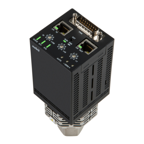
lAuto zero point adjustment
(1) Apply a vacuum with a pressure of 1/20,000 or less of the selected
pressure range.
(2) Keep the auto zero point adjustment button pressed for 3s. After
zero point adjustment:
• If the bias adjustment value is within ± 5%FS, the status LED
flashes green three times.
• If the bias adjustment value is between ±5 and ±20%FS, the sta-
tus LED flashes orange three times.
Handling Precautions
• Auto zero point adjustment cannot be done in the following
cases even if the button is pressed:
• Before warm-up is complete.
• If an error occurs.
• If the required bias adjustment value is beyond ±20%FS.
In these cases, the status LED flashes alternately red and orange
three times.
lManual zero point adjustment
(1) Apply a vacuum with a pressure of 1/20,000 or less of the selected
pressure range.
(2) The 0-10V output voltage changes when the up/down zero adjust-
ment button is pressed. Adjust the output voltage to 0.
When the button is pressed, the speed at which the 0-10V value
changes depends on how long the button is pressed. Keep it pressed for
a long time to do a quick rough adjustment. Afterwards, press it repeat-
edly for a short time to make fine adjustments.
• During adjustment using the up/down zero point button:
•
If the bias adjustment value is within ±5%FS, the status LED flashes green.
• If the bias adjustment value is between ±5 and ±20%FS, the status
LED flashes orange.
• The status LED stops flashing about 3s after the up/down zero point
adjustment button is released, and the bias adjustment value is then set.
•
Zero adjustment is restricted to the range in which the bias adjustment
value is ±20%FS. If the bias adjustment value reaches ±20%FS as the up/
down zero point adjustment button is pressed, the status LED flashes red.
Handling Precautions
• Manual zero point adjustment cannot be done in the following
cases even if the button is pressed:
• Before warm-up is complete.
• If an error occurs.
• If the pressure value exceeds the measurement range.
In these cases, the status LED flashes alternately red and orange
three times.
lResetting of bias adjustment value
To reset the bias adjustment value to its factory setting, keep the auto
zero point adjustment button pressed for 30s or longer. The zero point
is adjusted after 3s, and the bias value is reset after 30s. The status
LED then flashes alternately green and orange three times.
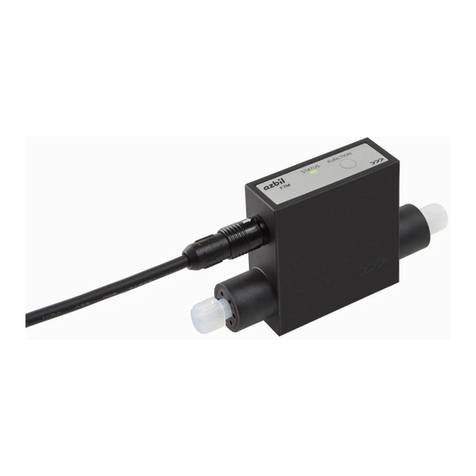
Status LED display operation
Status LED Status
Lit green Normal operation status (after warm-up)
Lit orange
Warm-up in progress (device temperature is not yet
stable)
Lit red Abnormal status (a problem with the device)
Flashing red
(0.3s,0.3s)
Abnormal status (operating environment problem,
such as excessive ambient temperature or wrong
power voltage)
3 green flashes
(0.3s,0.3s)
Automatic zero point adjustment (by pressing the
auto zero point adjustment button) is complete, and
the bias adjustment value is within ±5%FS.
3 orange flashes
(0.3s,0.3s)
Automatic zero point adjustment (by pressing the
auto zero point adjustment button) is complete. The
bias adjustment value is between ±5 and ± 20%FS.
Flashing green
(0.1s,0.1s)
The zero point is being adjusted with the up/down
zero point adjustment buttons. The bias adjustment
value is within ±5%FS.
Flashing orange
(0.1s,0.1s)
The zero point is being adjusted with the up/down
zero point adjustment buttons. The bias adjustment
value is between ±5 and ±20%FS.
Flashing red
(0.1s,0.1s)
During zero point adjustment with the up/down zero
point adjustment buttons, the bias adjustment value
reached the maximum adjustable range of ±20%FS.
Lit alternately
red and orange
3times (0.3s,0.3s)
The auto or up/down zero adjustment button
was pressed but conditions did not permit zero
adjustment.
Lit alternately
green and orange
3times (0.3s,0.3s)
The bias adjustment value has been reset.
Alternating green
and
orange with occa-
sional
red (1.9s,0.1s)
The event relay is latched.*1
Lit alternately
green and red.
(0.3s,0.3s)
Output is manually controlled.*2
Off The device is not powered up.
*1 Latching of the event relay must be set up with the Smart Loader (sold
separately).
*2 Output can be manually controlled with the Smart Loader (sold
separately).
MAINTENANCE AND TROUBLESHOOTING
Maintenance
lMaintenance and inspection
• Check that the status LED is green during operation.
• Check periodically that there are no leaks in the piping.
• Adjust the zero point periodically.
lCleaning
• Use a soft dry cloth.
• Do not use any organic solvent such as paint thinner or benzene.
lPart replacement
Do not disassemble the device or attempt to replace any of its parts.
Alarm displays and corrective actions
The following table shows the alarm displays and corrective actions to
take if there is a problem:
Status LED
Status Possible Causes Action
Flashing
red
Alarm
•
Temperature of electronic circuits
• Temperature of sensor head
• Heater temperature error
• Self-heating control error
• Wrong supply power voltage
Turn off the power and
check the power voltage,
ambient temperature, and
other operating conditions.
Lit red Failure
•
Heater wire break
•
Memory failure
•
Electronic circuit failure
Turn off the power and con-
tact the azbil Group or your
dealer, agent, or salesperson.
The device needs to be re-
paired by Azbil Corporation.
Important notice: If you send this device to Azbil Corporation for repair, fill
out the Safety Sheet on page 8 and include it with the device.
