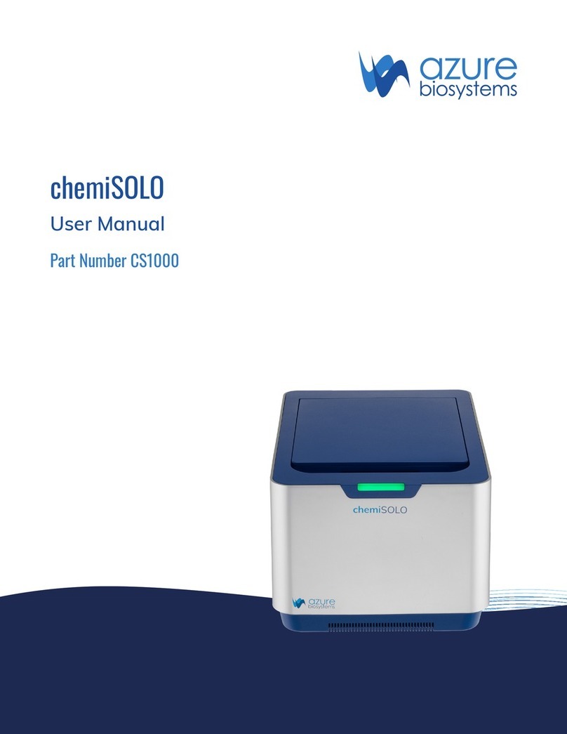
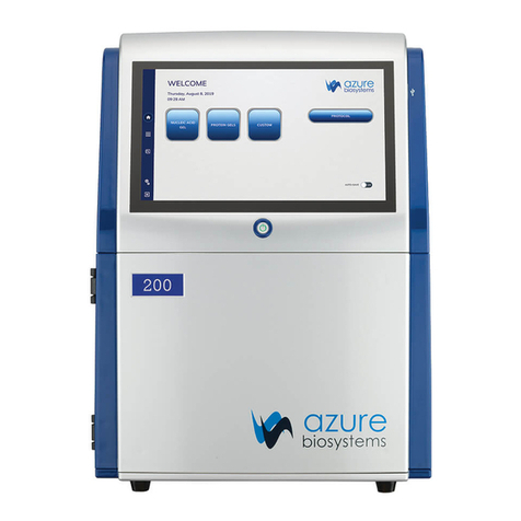
Azure Biosystems Sapphire User manual

Sapphire™ Biomolecular Imager User Manual Page 1
Sapphire™
Biomolecular Imager
User Manual
Rev 20190405

Sapphire™ Biomolecular Imager User Manual Page 1
Safety and Regulatory Compliance
Radiation
Radiation hazard prevention
The Sapphire Molecular Imager is not equipped with any radioisotope or radiation generating unit, and is
therefore not regulated by radiation hazard prevention laws. However, the Sapphire is capable of scanning
storage phosphor screens, which may be polluted by radioisotopes.
CAUTION: If radioisotope (RI) pollution occurs, stop use of the instrument immediately and follow the
instructions of your radiation administrator.
Laser Safety
WARNING: Making adjustments or carrying out procedures not specied in this manual, can result in
harmful exposure to laser radiation.
The Sapphire Biomolecular Imager is a Class I laser instrument that houses four Class IIIB lasers inside the
instrument.
Under the specied operating procedures, the instrument does not allow operator exposure to laser light. The
lasers, with power of 5–25mW, are accessible in the interior of the instrument.
General Information
The Azure Biosystems Sapphire imaging systems include a laser illumination system that provides up to
four narrow band excitation wavelengths for uorescent applications. The imaging systems are certied to
comply with CE, cTUVus and CB Scheme compliance standards and consists of two fully enclosed electronic
modules located inside of the imager. This laser system is by its appropriate classication and denition
a non-removable laser system as it is not operable when the laser modules themselves are removed from
within the system.
Safety Features
Azure Biosystems Sapphire Biomolecular Imaging Systems are designed to prevent direct and collateral
human exposure to radiation by means of a safety switch on the front side of the imager. The switch reacts to
“lid open” and “lid closed” states and defeats all power to internal light sources when the lid is in the “open”
position. Lasers and other internal system light sources will not power on unless the lid is fully closed. If the
access lid is opened during imaging, all light sources will immediately power off to prevent human exposure
to internal illumination sources. In addition, the entire laser system is fully enclosed within the system
enclosure and there are no viewing ports, windows, or openings to facilitate viewing of, or exposure to,
radiation elds from direct impact, reection, or leakage.
Maintenance
The Azure Biosystems Sapphire laser systems do not require regular, periodic, or preventative maintenance
in the form of adjustments, calibrations, or other standard maintenance procedures to maintain optimal
performance, thereby removing the need for users or their service technicians to initiate any actions where
exposure to laser radiation would occur.

Sapphire™ Biomolecular Imager User Manual Page 2
Serviceability
Replacement of faulty laser modules is a manufacturer-only repair action and not a customer-service
action. Laser repair or replacement may be performed in the eld by Azure Biosystems authorized service
technicians, or by return of the entire system to Azure Biosystems, or its authorized service location(s) for
laser repair or replacement. Lasers are deemed to be faulty or defective if users discover images that show
evidence of output signal level loss, a signicant difference between the output signal levels between laser
modules, or complete loss of output signal level in a laser module. Users or their service technicians should
make no attempt to determine the cause of faulty laser operation, and should promptly contact Azure
Biosystems at support@azurebiosystems.com or their nearest Azure Biosystems authorized service location.
Caution
The safety switch in the Sapphire is designed to prevent you from being exposed to the laser radiation. If
you open the sample lid while the scanner is in operation, the laser safety switch cuts power to the lasers.
Exposure to laser radiation can be harmful, and viewing laser light directly, can cause blindness.
Azure Biosystems Sapphire systems contain a defeatable safety switch system. It is not recommended or
advised by Azure Biosystems, under any circumstances, for users to defeat the safety system and perform
laser imaging, or imaging with any light source with the access lid open. The access lid must be fully closed.
Electrical Safety Precautions
Be sure to take proper precautions when handling any electrical equipment. NEVER work on any live circuit,
xture, receptacle, or switch. Safety rules you should follow whenever working with any electrical appliance
include:
•Always shut off power at the main disconnect before changing a fuse.
• Always shut off power to the circuit before repairing or replacing a switch, receptacle, or xture.
• Always tape over the main switch, empty fuse socket, or circuit breaker you are working on.
• Always check that the circuit is dead before beginning work on it. Using a circuit tester or voltmeter can
help you determine this.
•Always unplug any appliance before repairing it.
Protective earth terminal
The ground terminal, intended for connection to an external protective conductor for protection
against electric shock in case of a fault, is located on the inside back panel.
For Research Use Only
This instrument is suitable for research use only. It must be used, therefore, only by personnel who know the
health risks associated with the reagents that are normally used with this instrument.

Sapphire™ Biomolecular Imager User Manual Page 3
Warranty
The Azure Sapphire products are warrantied against defects in materials and workmanship for one year
unless otherwise outlined on your sales order or www.azurebiosystems.com/warranty. If any defect occurs in
the instrument during this warranty period, Azure Biosystems, Inc. will repair or replace the defective parts at
its discretion without charge. The following defects, however, are specically excluded:
•Defects caused by improper operation.
• Repair or modication done by anyone other than Azure Biosystems or the company’s authorized agent.
•Use of spare parts supplied by anyone other than Azure Biosystems.
•Damage caused by accident or misuse.
•Damage caused by disaster.
•Corrosion caused by improper solvents or samples.
Voltage Setting Information
The Azure Sapphire Biomolecular Imaging System has a power supply that automatically chooses the correct
voltage for your country or region.
Certicates of Conformity
CE Conformity
The following Azure™ Sapphire Biomolecular Imager, models: RGB, NIR, RGBNIR, are in conformity with the
provisions of the following CE Directives, including all amendments, and national legislation implementing
these directives:
•Low Voltage Directive 2006/95/EC
•EMC Directive 2014/30/EU
And that the following harmonized standards have been applied:
• EN61010-1: 2001
• EN61326-1: 1997+A1:1998+A2:2001+A3:2003 Class A
• EN61000-4-2, EN61000-4-3, EN61000-4-4, EN61000-4-5, EN61000-4-6, EN61000-4-11
Protection category: IP20 according IEC 60529
Contact
6747 Sierra Court, Suite A-B •Dublin, CA 94568 •USA
Phone: (925) 307-7127 (9am-4pm Pacic time) •To dial from outside of the US: +1 925 307 7127
Fax: (925) 905-1816 •Email: info@azurebiosystems.com
Legal
Sapphire is protected by one or more U.S. and/or foreign patents listed at
www.azurebiosystems.com/patents.

Sapphire™ Biomolecular Imager User Manual Page 4
Table of Contents
1. Introduction 5
1.1 Key Components and Applications 5
1.2 Optional Modules 5
1.3 Optional Modications 5
1.4 Table of Specications 6
2. Installation and Setup 7
2.1 System Placement 7
2.2 Connecting to Power 7
2.3 Power On/Off the System 7
2.4 Software Installation 7
2.5 Connecting Other USB Devices to the System 8
3. Proper Usage – Read Before Use 9
4. Sapphire Capture Software Overview 10
4.1 Launch the Sapphire Capture Software 10
4.2 Fluorescence Imaging 10
4.2.1 Scanning a Fluorescent Membrane 13
4.2.2 Scanning a Fluorescent Gel 14
4.2.3 Scanning a Fluorescent Slide 15
4.2.4 Scanning a Fluorescent, Plate-Based Assay 16
4.3 Chemiluminescence Imaging 18
4.3.1 Taking a Chemi Image 20
4.4 Phosphor Imaging 21
4.4.1 Scanning a Storage Phosphor Screen 22
4.5 Visible Imaging 23
4.6 The Image Gallery 24
5. Settings 28
5.1 General Settings 28
5.2 Advanced Settings, Create Darkmasters, Create Flats 28

Sapphire™ Biomolecular Imager User Manual Page 5
1. Introduction
The Azure Sapphire Biomolecular Imager is a next generation laser scanning system that provides you
with exceptional data quality through extremely sensitive detection, ultra-high resolution and broad linear
dynamic range.
The Sapphire family of instruments includes the following products:
• Sapphire NIR
•Sapphire RGB
• Sapphire RGBNIR
•Sapphire PI
All models are compatible with optional chemiluminescence and phosphor imaging modules.
1.1 Key Components and Applications
Model Key Components Applications
Sapphire RGB 488nm LD, 520nm LD, 658nm LD RGB visible uorescence imaging
Sapphire NIR 685nm LD, 784nm LD NIR uorescence imaging
Sapphire RGBNIR 488nm LD, 520nm LD, 658nm LD,
784nm LD
RGB and NIR uorescence imaging
Sapphire PI 658LD Phosphor-imaging
1.2 Optional Modules
•Phosphor – Imaging phosphor screens exposed to radioactive samples
•Chemi – Imaging chemiluminescent samples with sensitivity of lm
•Q-Module – Add dye exibility and increase quantitative capability by adding 520 laser channel to
Sapphire Biomolecular Imager – NIR
•488 Laser Module – Add dye exibility by adding 488 laser channel to Sapphire Biomolecular Imager – NIR
1.3 Optional Modications
•Cy5 Modication – Modify the red channel of any Sapphire Biomolecular Imager to a 638nm laser
and detector
•Cy5.5 Modication – Modify the 685 channel of a Sapphire Biomolecular Imager - NIR to a 658nm laser
and detector
•NIR700 Modication – Modify the red channel of any Sapphire Biomolecular Imager to a 685nm laser
and detector

Sapphire™ Biomolecular Imager User Manual Page 6
1.4 Table of Specications
Sapphire NIR Sapphire RGB Sapphire RGBNIR Sapphire PI
Part number IS1024 IS1025 IS1026 IS1027
Laser excitation
wavelengths
685, 784 488, 520, 658 488, 520, 658, 784 658
Bit depth 16 bit 16 bit 16 bit 16 bit
Scanning area 25 cm X 25 cm 25 cm X 25 cm 25 cm X 25 cm 25 cm X 25 cm
Scanning modes Simultaneous, Sequential Simultaneous, Sequential Simultaneous, Sequential Phosphor-imaging
Pixel size 10 micron – 1000 micron 10 micron – 1000 micron 10 micron – 1000 micron 10 micron – 1000 micron
Detectors Avalanche Photodiode Photomultiplier Tube,
Avalanche Photodiode
Photomultiplier Tube,
Avalanche Photodiode
Photomultiplier Tube
Scanning speed 50 cm/s 50 cm/s 50 cm/s 50 cm/s
Filters Red 725BP40,
IR 832BP37
Blue 518BP22,
Green 565BP24,
Red 710BP40
Blue 518BP22,
Green 565BP24,
Red 710BP40,
IR 832BP37
Blue 390BP40
Dimensions
(W X H X D)
75 cm X 45 cm X 70 cm 75 cm X 45 cm X 70 cm 75 cm X 45 cm X 70 cm 75 cm X 45 cm X 70 cm
Weight 140 lbs 140 lbs 140 lbs 140 lbs
Power
requirements
100 – 240 VAC ± 10%,
50/60 Hz
100 – 240 VAC ± 10%,
50/60 Hz
100 – 240 VAC ± 10%,
50/60 Hz
100 – 240 VAC ± 10%,
50/60 Hz
Computer Options Windows 10 laptop
OR Windows 10 Pro
desktop with HD monitor
Windows 10 laptop
OR Windows 10 Pro
desktop with HD monitor
Windows 10 laptop
OR Windows 10 Pro
desktop with HD monitor
Windows 10 laptop
OR Windows 10 Pro
desktop with HD monitor
Chemiluminescent
Upgrade
Optional Optional Optional Optional
Imaging area,
chemiluminescent
16 cm X 13 cm 16 cm X 13 cm 16 cm X 13 cm 16 cm X 13 cm
Bit depth 16 bit 16 bit 16 bit 16 bit
Resolution 2688 X 2200 2688 X 2200 2688 X 2200 2688 X 2200
Imaging time 0-60 minutes 0-60 minutes 0-60 minutes 0-60 minutes
Visible imaging Yes Yes Yes Yes
Phosphor Imaging
Module
Optional Optional Optional N/A
Sample types Storage phosphor screen
(imaging plate)
Storage phosphor screen
(imaging plate)
Storage phosphor screen
(imaging plate)
Storage phosphor screen
(imaging plate)

Sapphire™ Biomolecular Imager User Manual Page 7
2.1 System Placement
WARNING! Excessive Weight Hazard – Please use two or more people to lift the system. Failure to do so
can result in system damage and personal injury.
As with all electrical instruments, the Azure Sapphire Biomolecular Imager should be located away from
water, solvents, or corrosive materials, on a at and stable surface with adequate clearance on all sides. The
system must remain stationary during operation. Further, the system should be placed away from interfering
electrical signals and magnetic elds. If possible, a dedicated electrical outlet should be used to eliminate
electrical interference from other instrumentation in your laboratory. The Azure Sapphire Biomolecular Imager
should be installed at no more than 3000 meters above sea level.
2.2 Connecting to Power
The power entry module is located in the lower right on the back panel of the system. Connect the power cord
to a secure power outlet.
It is important to connect the system to a well-grounded power source.
2.3 Power On/Off the System
To turn on the system
1. Switch on the system master power by ipping the power switch on the back right panel
of the instrument to the on ( | ) position.
2. Once the power is on to the system, wait for the light panels to stop changing color, and
then the system is ready to turn on.
3. Press and hold the power button on the front left of the instrument for 5 seconds. The
system is now ready to use.
To turn off the system
1. Push the power button on the front of the system for 5 seconds to put the system in standby mode
2. Turn off master power to the system using the power switch on the back of the instrument.
Azure Biosystems recommends leaving the system master power turned on via the switch on the back panel,
as this switch may not be easily accessible.
2.4 Software Installation
The Azure Sapphire Software is pre-installed. To launch the software, double click on the
desktop icon. The system will take a few seconds to initialize.
Once the system is done initializing, the software displays the Imaging tab, and is ready
to use.
2. Installation and Setup

Sapphire™ Biomolecular Imager User Manual Page 8
2.5 Connecting Other USB Devices to the System
The external computer is connected to the Sapphire system via a USB 3 connection.
You may attach regulatory approved, Windows OS supported USB keyboard, USB mouse or other USB input
devices to any of the unused USB ports that remain on the external PC.

Sapphire™ Biomolecular Imager User Manual Page 9
3. Proper Usage – Please Read Before Use
DO DO NOT
Wipe the imaging surface with ultrapure water,
70% ethanol or isopropyl alcohol if available, and a
lint free wipe.
Wipe the surface with anything else. Many
detergents and cleaning chemicals have uorescent
properties which will interfere with the scanning of
uorescent blots.
Leave the system master power on at the back. Attempt to access the back switch unless it is
readily accessible.
Keep the system computer connected, on a table
near by.
Put the system computer on top of the scanning
apparatus. The heat generated by the PC may
damage the unit.
Keep the top of the Sapphire Biomolecular
Imager clear.
Put anything on top of the imager. The Sapphire
was not designed to withstand forces acting down
on top of the imager.
Remove your samples from the imager
when nished.
Leave your samples in the imager. Many samples
can contain hazardous chemicals, such as ethidium
bromide or radiolabeled proteins, that can cause
damage or distress to the next samples or users.
Leave your system where it is installed. Move your Sapphire. The Sapphire Imager weighs
135lbs (61kg) and is not designed to be moved.
Moving the Sapphire Imager, without the express
permission of Azure Biosystems, may void warranty
or service contracts covering the imager.
Close the imaging lid whilst imaging. Leave the imaging lid open while imaging. A
safety mechanism disarms the lasers and prevents
them from turning on when the imaging lid is not
properly shut.
Call Azure Biosystems, or email
support@azurebiosystems, in the event of an
issue with the instrument.
Attempt to x the instrument yourself as some of
the components may be hazardous.

Sapphire™ Biomolecular Imager User Manual Page 10
4. Sapphire Capture Software Overview
4.1 Launch the Sapphire Capture Software
Double click the Sapphire desktop icon to launch the scanner software.
4.2 Fluorescence Imaging
The Fluorescence module utilizes lasers and PMT or APD detectors to scan uorescent samples.
1
2
3
4
5 6
7
9
10
11
1213
15
17
18
8
14
16
1
2
3
4
5 6
7
9
10
11
1213
15
17
18
8
14
16

Sapphire™ Biomolecular Imager User Manual Page 11
1. FLUORESCENCE – Select the uorescence tab at the top of the imaging section.
2. IMAGING AREA – The Imaging Area represents the glass scanning surface of the Sapphire Biomolecular
Imager with each square in the Imaging Area grid representing one square centimeter. Use the green
corners to select the area of the imaging screen covered by your sample.
Note the letter and number coordinates surrounding the glass scanning surface correspond to the same
letters and numbers in the Imaging Area selection grid. Ensure the sample is contained wholly within the
designated imaging area.
Note: Any portions of sample that fall outside the imaging area will not be captured in the nal image.
Note: Scanning time is impacted by increases in the Y-axis. To decrease scanning time, place long
samples along the X-axis.
3. PROTOCOL – Several scanning protocols are preset within the software for easy imaging set up. Use
the Protocol drop down menu to select from these preset methods, select a previously saved imaging
protocol or to set up a new protocol.
4. PIXEL SIZE – Adjust the scanning resolution by selecting the pixel size. A smaller pixel size will result in a
higher resolution image. Smaller pixel sizes allow for more detailed capture and analysis but will take a
longer time to acquire.
5. SCAN SPEED – Selects the speed at which the scanning head travels. A slower scan speed can produce
more accurate signal to noise ratios for low concentration samples by increasing the sampling per pixel
but will greatly increase the scanning time. For most applications, Highest scan speed is recommended.
Note: Slower scan speeds to do not increase the signal measured.
6. SAMPLE TYPE – Changing the Sample Type adjusts the focal plane of the scan. Selecting Custom
Sample Type will bring up a slider that allows adjustment of the focal plane from 0mm to 4.0mm above
the glass. Note that Custom focal distances are not saved in Image Info. Once the optimal focal plane of a
sample is determined through the Custom function, it is recommended that the specic sample type and
focal plane be added in Settings so that it can be recalled in the image info and for future scans.
Sample Type Focal Plane
Membrane 0mm On the glass (0mm)
Gel +0.5mm 0.5mm above the glass
Plate +3.0mm 3mm above the glass
Slide +1.0mm 1mm above the glass
Custom Adjustable
7. DYE – Select scanning wavelengths by using the drop-down menu to select from the available list of
dyes. The corresponding excitation and emission wavelengths are noted on the right hand side of the
selected dye.
Note: If a specic dye is not listed, choose one with a similar excitation and emission, or add it to the list
in Settings.

Sapphire™ Biomolecular Imager User Manual Page 12
8. INTENSITY – Adjust the power of each laser by selecting the appropriate Intensity level with 1 (one)
being the lowest power and 10 (ten) being the highest. A higher laser intensity will increase the
sensitivity and allow for better detection of lower concentrations of sample, but too high of an intensity
may cause saturation and increased background and may bleach your uorophores more quickly.
9. COLOR – Choose which color to represent each dye/wavelength in the preview image during scanning.
Note that coloring does not affect image capture or data.
10. ADD SCAN – Add additional scanning channels to the protocol. To remove an unwanted channel/dye,
press the X located on the top right corner of the channel box.
11. SAVE PROTOCOL – Save a scanning method to the Protocol drop down to make it easier to access
frequently used settings and protocols. Saved methods and protocols can also be deleted.
12. SAVE IMAGES – Choose whether or not to have images Autosave upon scan completion. Enter an le
name in the Image Name eld (default name is YYYY-MMDD-TTTTTT), and select or create a folder for
images to be saved in by pressing the Browse button. Clicking on the blue link next to Location will take
you to the current active save folder. Any comments entered in the Notes eld will save with the le upon
scanning completion. The save window will minimize when Auto Save is turned off.
13. FILE SIZE – The estimated image le size based on the current selected parameters (Scan Area, Pixel
Size, and Scan Speed all effect File Size) will appear below the Auto Save window. File Size is listed as
the size for each individual channel with the Total le size listed in parenthesis.
14. SEQUENTIAL SCAN – By default, the Sapphire Biomolecular Imager scans all channels simultaneously.
Turning Sequential Scanning ON scans each channel individually from rst channel selected to last
instead of scanning simultaneously.
Note: With Sequential Scanning the estimated Scan Time is per channel.
15. SCAN – The estimated scan completion time for the area and parameters selected will be displayed
next to Scan Time. Select PRESCAN to initiate a low resolution, unsaved scan. Prescans are useful in
determining correct sample orientation and positioning, scan area and intensity settings. Select SCAN to
initiate a scan using the set parameters.
16. SMARTSCAN – SmartScan automatically determines the optimal intensity level of a sample prior to
scanning. To use SmartScan, set all scan parameters and scanning area (Intensity does not need to be
set.) and click SmartScan. The system will determine and set the proper intensity level and perform a
nal scan according to set parameters.
17. CONTRAST SETTINGS – Select Contrast Settings to open the preview contrasting window. The blue
circle buttons displayed under Channels correspond to the currently engaged lasers. Clicking on these
buttons will activate or inactivate the preview image for that channel.
Use the sliders under Contrast to adjust the contrast of the preview image. Contrast can be adjusted for
each individual channel or for the preview image as a whole. NOTE: Adjusting the contrast only adjusts
how the preview image is visualized. It does not affect the nal data or image.
18. ZOOM – Use the slider or the (-) and (+) buttons to zoom in on the Imaging Area. This is useful for small
area scans and viewing the image preview of specic areas of the scan.

Sapphire™ Biomolecular Imager User Manual Page 13
4.2.1 Scanning a Fluorescent Membrane
1. Place your membrane, protein side down, on the glass scanning surface. Make sure that the sample is
wholly contained within the imaging grid (A 0 – Z 25).
2. Azure recommends placing the imaging mat black side down on top of your membrane to keep it ush
against the glass imaging surface. For best results, also use Azure’s Background Quenching Sheets.
3. Click the FLUORESCENCE tab in the capture software to enter the uorescence scanning module.
4. Select the area you would like to scan by dragging the corners of the box over the area covered by your
membrane. The estimated scanning time will appear at the bottom of the capture window.
5. Select the desired Protocol from the drop down menu (NIR Western, Visible Fluorescent Western,
4 Channel Western) or select New Method to create a new method.
6. Choose the desired resolution and scan speed. Then set the Sample Type to Membrane. This sets the
focal plane to the level of the glass scanning surface.
7. If creating a New Method, use the drop down menus to select the dye you are using along with the color
you would like the signal to appear in the preview image. Add additional dyes to any method by clicking
the (+) Add Scan button.
8. Change the signal Intensity to your preference for the sample you are imaging. Use Intensity 1 (one) to
scan strong signals and Intensity 10 (ten) to detect weaker signals. NOTE: Use the PRESCAN function
to initiate a quick, low resolution scan to help determine the best Intensity Level to use OR select
SMARTSCAN after all parameters are set to have the system determine the scan intensity before
automatically performing the nal scan.
9. Enter or Edit the le name under Image Name. By default, the image will save as YYYY-MMDD-TTTTTT
where time is HHmmss.
10. Use the Auto Save switch to turn Auto Save ON or OFF. If Auto Save is ON, use the Browse button to
select where to save the auto saved images.
11. Clicking PRESCAN will initiate a quick, low resolution scan that can be useful in determining the correct
membrane positioning, scanning area and intensity setting.
12. If no Prescan is needed, select SCAN to initial scanning at the set parameters, OR select SMARTSCAN to
have the system determine the scan intensity and scan at the set parameters.
13. A preview image will appear in the selected scanning area. Use the blue channel buttons beneath the
capture window to select which channels are visible in the preview image.
14. During scanning, visualization of the preview image may be adjusted by clicking on the Contrast Settings
button. This will open a Channels window that will allow you to select which channels to preview and
adjust contrast.
Note: Adjusting the contrast through this window only affects visualization of the captured image. It does
not affect captured data.
15. Upon completion of the scan, images will appear according to the color chosen for each channel.
Multiplexed scans will appear as a single image, and can be separated into individual signal channels for
analysis. If Sequential Scanning was chosen, each individual channel will appear as a grayscale image
along with the nal multiplexed image.

Sapphire™ Biomolecular Imager User Manual Page 14
4.2.2 Scanning a Fluorescent Gel
1. Place your gel on the glass scanning surface. Make sure that the sample is wholly contained within the
imaging grid (A 0 – Z 25).
2. Azure recommends using Background Quenching Sheets to create a at, black background and protect
your gel before placing the imaging mat black side down on top of your gel.
3. Click the FLUORESCENCE tab in the capture software to enter the uorescence scanning module.
4. Select the area you would like to scan by dragging the corners of the box over the area covered by your
gel. The estimated scanning time will appear at the bottom of the capture window.
5. Select the desired Protocol from the drop down menu (NIR Western, Visible Fluorescent Western,
4 Channel Western)or select New Method to create a new method.
Note: Western Protocols set the sample type to Membrane by default. This sets the focal plane to 0mm
(the level of the glass).
6. Choose the desired resolution and scan speed. Then set the Sample Type to Gel. This sets the focal
plane to 0.5mm above the glass scanning surface. This focal plane is ideal for gels of approximately
1.0mm thickness.
Note: For thicker gels or to set a different focal plane, choose the Sample Type Custom and use the slider
to set the focal plane.
7. If creating a New Method, use the drop down menus to select the dye you are using along with the color
you would like the signal to appear in the preview image. Add additional dyes to any method by clicking
the (+) Add Scan button.
8. Change the signal Intensity to your preference for the sample you are imaging. Use Intensity 1 (one) to
scan strong signals and Intensity 10 (ten) to detect weaker signals. NOTE: Use the PRESCAN function
to initiate a quick, low resolution scan to help determine the best Intensity Level to use OR select
SMARTSCAN after all parameters are set to have the system determine the scan intensity before
automatically performing the nal scan.
9. Enter or Edit the le name under Image Name. By default, the image will save as YYYY-MMDD-TTTTTT
where time is HHmmss.
10. Use the Auto Save switch to turn Auto Save ON or OFF. If Auto Save is ON, use the Browse button to
select where to save the auto saved images.
11. Clicking PRESCAN will initiate a quick, low resolution scan that can be useful in determining the correct
gel positioning, scanning area and intensity setting.
12. If no Prescan is needed, select SCAN to initiate scanning at the set parameters, OR select SMARTSCAN
to have the system determine the scan intensity and scan at the set parameters.
13. A preview image will appear in the selected scanning area. Use the blue channel buttons beneath the
capture window to select which channels are visible in the preview image.
14. During scanning, visualization of the preview image may be adjusted by clicking on the Contrast Settings
button. This will open a Channels window that will allow you to select which channels to preview and
adjust contrast.

Sapphire™ Biomolecular Imager User Manual Page 15
Note: Adjusting the contrast through this window only affects visualization of the captured image. It does
not affect captured data.
15. Upon completion of the scan, images will appear according to the color chosen for each channel.
Multiplexed scans will appear as a single image, and can be separated into individual signal channels for
analysis. If Sequential Scanning was chosen, each individual channel will appear as a grayscale image
along with the nal multiplexed image.
4.2.3 Scanning a Fluorescent Slide
1. Place your slide sample side up on the glass scanning surface. Make sure that the sample is wholly
contained within the imaging grid (A 0 – Z 25).
2. Azure recommends using a Background Quenching Sheet behind your sample before placing the imaging
mat black side down on top of your slide.
3. Click the FLUORESCENCE tab in the capture software to enter the uorescence scanning module.
4. Select the area you would like to scan by dragging the corners of the box over the area covered by your
slide. The estimated scanning time will appear at the bottom of the capture window.
5. Select the desired Protocol from the drop down menu (NIR, Visible Fluorescent Western, 3 Channel
Image) or select New Method to create a new method.
6. Choose the desired resolution and scan speed. Then set the Sample Type to Slide. This sets the focal
plane to 1mm above the glass scanning surface.
Note: If you prefer to place your slides with the sample side down, select Membrane as the Sample Type
to set the focal plane level with the glass scanning surface, or select Custom and set the focus slider
to 0mm.
Note: For slides of a different thickness than 1mm, use the Custom Sample Type to select the appropriate
focal plane.
7. If creating a New Method, use the drop down menus to select the dye you are using along with the color
you would like the signal to appear in the preview image. Add additional dyes to any method by clicking
the (+) Add Scan button.
8. Change the signal Intensity to your preference for the sample you are imaging. Use Intensity 1 (one) to
scan strong signals and Intensity 10 (ten) to detect weaker signals. NOTE: Use the PRESCAN function
to initiate a quick, low resolution scan to help determine the best Intensity Level to use OR select
SMARTSCAN after all parameters are set to have the system determine the scan intensity before
automatically performing the nal scan.
9. Enter or Edit the le name under Image Name. By default, the image will save as YYYY-MMDD-TTTTTT
where time is HHmmss.
10. Use the Auto Save switch to turn Auto Save ON or OFF. If Auto Save is ON, use the Browse button to
select where to save the auto saved images.
11. Clicking PRESCAN will initiate a quick, low resolution scan that can be useful in determining the correct
slide positioning, scanning area and intensity setting.

Sapphire™ Biomolecular Imager User Manual Page 16
12. If no Prescan is needed, select SCAN to initiate scanning at the set parameters, OR select SMARTSCAN
to have the system determine the scan intensity and scan at the set parameters.
13. A preview image will appear in the selected scanning area. Use the blue channel buttons beneath the
capture window to select which channels are visible in the preview image.
14. During scanning, visualization of the preview image may be adjusted by clicking on the Contrast Settings
button. This will open a Channels window that will allow you to select which channels to preview and
adjust contrast.
Note: Adjusting the contrast through this window only affects visualization of the captured image. It does
not affect captured data.
15. Upon completion of the scan, images will appear according to the color chosen for each channel.
Multiplexed scans will appear as a single image, and can be separated into individual signal channels for
analysis. If Sequential Scanning was chosen, each individual channel will appear as a grayscale image
along with the nal multiplexed image.
4.2.4 Scanning a Fluorescent, Plate-Based Assay
1. Place your plate on the glass scanning surface with the wells facing up so that you are scanning the
bottom of the plate. Make sure that the sample is wholly contained within the imaging grid (A 0 – Z 25).
2. If possible, Azure recommends placing a black Background Quenching Sheet or the imaging mat black
side down over the plate.
3. Click the FLUORESCENCE tab in the capture software to enter the uorescence scanning module.
4. Select the area you would like to scan by dragging the corners of the box over the area covered by your
slide. The estimated scanning time will appear at the bottom of the capture window.
5. Select the desired Protocol from the drop down menu (NIR, Visible Fluorescent Western, 3 Channel
Image) or select New Method to create a new method.
Note: Western Methods set the Sample Type to Membrane by default, which sets the focal plane to 0mm
(the level of the glass).
6. Choose the desired resolution and scan speed. Then set the Sample Type to Plate. This sets the focal
plane to 3mm above the glass scanning surface.
Note: For most standard 96-well plates, 3mm is the distance between the bottom of the skirt to the
bottom of the wells. For best results, measure this distance for your individual plate type and use the
Custom Sample Type to set the correct focal plane. If you are unsure of the correct distance, scan
your plate at several different focal planes and choose the one that results in the highest signal and
sharpest image.
7. If creating a New Method, use the drop down menus to select the dye you are using along with the color
you would like the signal to appear in the preview image. Add additional dyes to any method by clicking
the (+) Add Scan button.
8. Change the signal Intensity to your preference for the sample you are imaging. Use Intensity 1 (one) to
scan strong signals and Intensity 10 (ten) to detect weaker signals. NOTE: Use the PRESCAN function to
initiate a quick, low resolution scan to help determine the best Intensity Level to use.

Sapphire™ Biomolecular Imager User Manual Page 17
9. Enter or Edit the le name under Image Name. By default, the image will save as YYYY-MMDD-TTTTTT
where time is HHmmss.
10. Use the Auto Save switch to turn Auto Save ON or OFF. If Auto Save is ON, use the Browse button to
select where to save the auto saved images.
11. Clicking PRESCAN will initiate a quick, low resolution scan that can be useful in determining the correct
sample positioning, scanning area and intensity setting.
12. If no Prescan is needed, select SCAN to initiate scanning at the set parameters.
13. A preview image will appear in the selected scanning area. Use the blue channel buttons beneath the
capture window to select which channels are visible in the preview image.
14. During scanning, visualization of the preview image may be adjusted by clicking on the Contrast Settings
button. This will open a Channels window that will allow you to select which channels to preview and
adjust contrast.
Note: Adjusting the contrast through this window only affects visualization of the captured image. It does
not affect captured data.
15. Upon completion of the scan, images will appear according to the color chosen for each channel.
Multiplexed scans will appear as a single image, and can be separated into individual signal channels
for analysis.

Sapphire™ Biomolecular Imager User Manual Page 18
4.3 Chemiluminescence Imaging
The Chemiluminescence Module utilizes a cooled CCD camera to image luminescent samples.
1
2
3
4
5 6
7
11
12
13
14
15
16
1. CHEMILUMINESCENCE – If your Azure Sapphire conguration includes the optional chemiluminescence
module, you will rst need to select this option in the “Imaging” section.
2. IMAGING AREA – The Chemi Imaging Area is designated by blue markings on the top left corner of the
imaging glass. Ensure that chemi samples are wholly contained within the markings. Any sample outside
of the marked area will not be imaged by the camera.
3. IMAGE CAPTURE – Select between Single, Cumulative and Multiple Image Capture modes.
4. SINGLE – Take a single chemiluminescent image with a predetermined exposure time, or by using the
Autoexpose function.
5. CUMULATIVE – Selecting Cumulative will tell the software to take up to 10 images at the time interval
you selected for exposure times.
For example: if you set an exposure time of 1 minute, the system will capture and display one image
every minute cumulating each exposure, up to ten exposures. The rst image displayed will be a 1 minute
exposure. The second image displayed, at the 2 minute interval, will be a two minute exposure. The nal,
tenth image, will be the sum of 10, 1 minute images. Images appear and can be viewed in the Gallery tab
as they are acquired.
6. MULTIPLE – Select between 1 and 10 images. The exposure time for each individual image can be set
independently. The images are not stacked. Use the arrow buttons to move between the frames when
setting the exposure times.
17

Sapphire™ Biomolecular Imager User Manual Page 19
7. AUTO EXPOSURE – If you are unsure of the required exposure time for you chemiluminescent sample,
select Autoexposure to let the software calculate one for you. When Auto exposure is turned on, three
different exposure options appear.
8. OVEREXPOSURE – The software will calculate an exposure time that saturates the brightest bands in
the blot to potentially capture weaker signals. This is useful for blots where the brightest bands may not
be the bands of interest.
9. WIDE DYNAMIC RANGE – The software will calculate an exposure time that is long enough to capture
the widest range of signal while avoiding saturation. This autoexposure method is well suited to
most blots.
10. UNDEREXPOSURE – The software will optimize a short exposure time to the brightest signal on the blot.
Weaker signals may not be visualized in an underexposed image.
11. EXPOSURE TIME – If you know your preferred exposure time, enter it here. For capturing in the multiple
image mode, select the time for each exposure. In the cumulative imaging mode, select the time interval
for each image to be taken.
12. SENSITIVITY – Changing the sensitivity settings changes both the sensitivity and the resolution of
the camera and image. A lower sensitivity setting results in a higher resolution image, while a higher
sensitivity setting results in a lower resolution image due to the binning of the pixels. The resolution is
displayed under the sensitivity settings.
13. MARKER – If Marker is selected, the system will acquire a white light image of your protein marker/
ladder after capture of the chemi image. This can be overlaid on top of the chemi image, maintaining the
positions on the gel or membrane.
Note: When the Marker function is selected and turned on, the button will appear blue. When the Marker
function is off, the button will appear gray.
14. CAPTURE – Click the capture icon to capture the image according to the set parameters.
15. CCD COOLED INDICATOR – The Sapphire is equipped with a CCD capable of cooling down to 50
degrees C below ambient temperature. The CCD Cooled indicator will turn green when the CCD has
reached optimal cooling. A cooled CCD is useful for noise reduction in long exposures. It is not necessary
to wait for the CCD to reach optimal cooling when expecting exposures to remain under a minute.
16. LIVE – Selecting this view will allow you to see a live view through the ccd camera enabling you to check
the alignment of your blot in the eld of view.
17. SAVE IMAGES – Choose whether or not to have images Autosave upon image capture. Enter an le
name in the Image Name eld (default name is YYYY-MMDD-TTTTTT), and select or create a folder for
images to be saved in by pressing the Browse button. Clicking on the blue link next to Location will take
you to the current active save folder. Any comments entered in the Notes eld will save with the le upon
scanning completion. The save window will minimize when Auto Save is turned off.
Table of contents
Other Azure Biosystems Laboratory Equipment manuals
Popular Laboratory Equipment manuals by other brands

primotec
primotec Metalight Mini Installation and operating instruction

Infors
Infors Multitron operating manual

DoorBird
DoorBird A1091 Series installation manual

Associated Research
Associated Research OMNIA II 8204/8254 quick start guide

Codonics
Codonics Horizon GS manual

VWR
VWR avantor instruction manual