AZZURRO CONNEXT User manual

Identification: MD-AL-GI-00
Rev. 4.0 of 09/11/2020 - Application: GID
Zucchetti Centro Sistemi S.p.A. - Green Innovation Division
Via Lungarno, 248 - 52028 Terranuova Bracciolini - Arezzo, Italy
tel. +39 055 91971 - fax. +39 055 9197515
Reg. Pile IT12110P00002965 - Share Capital € 100,000.00 fully paid up
AR Company Reg. no. 03225010481 - REA AR no. 94189
ISO 9001 Certified Company - Certificate no. 9151 - CNS0 - IT-17778
Connext User Manual
Rev. 1.2 24/05/2021
“CONNEXT” Control System
User Manual

Solo documento principale.
2/45
Identification: MD-AL-GI-00
Rev. 1.0 28.01.21 - Application: GID
Connext User Manual
Rev. 1.2 24/05/2021
General instructions
This manual contains important safety instructions that must be followed during installation and
maintenance of the equipment.
Please keep these instructions!
This manual must be considered an integral part of the equipment, and must be available at all
times to everyone who interacts with the equipment. The manual must always accompany the
equipment, even when it is transferred to another user or plant.
Copyright statement
The copyright of this manual belongs to Zucchetti Centro Sistemi S.p.A. No part of this manual
(including the software, etc.) may be copied, reproduced or distributed in any form or by any
means without the permission of Zucchetti Centro Sistemi S.p.A. All rights reserved. ZCS reserves
the right to final interpretation. This manual is subject to change based on feedback from users,
installers or customers. Please check our website http://www.zcsazzurro.com for the latest
version.
Zucchetti Centro Sistemi
Via Lungarno 305/A
52028, Terranuova Bracciolini (AR)
+39 055 91971
info@zcscompany.com
http://www.zcscompany.com

Solo documento principale.
3/45
Identification: MD-AL-GI-00
Rev. 1.0 28.01.21 - Application: GID
Connext User Manual
Rev. 1.2 24/05/2021
Table of Contents
1. Preliminary safety instructions ..............................................................................................................................7
1.1. Safety instructions...............................................................................................................................................7
1.2. Symbols and icons...............................................................................................................................................9
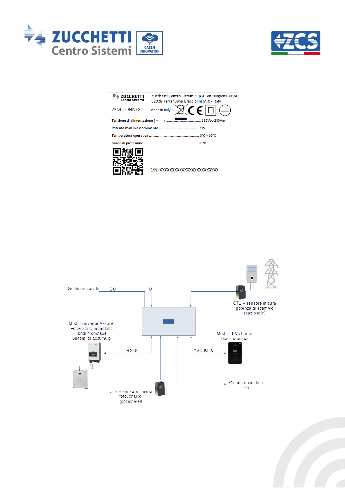
1.3. Labels .................................................................................................................................................................... 10
2. Product features ........................................................................................................................................................ 10
2.1. Product presentation ...................................................................................................................................... 10
2.2. Product overview ............................................................................................................................................. 11
2.2.1. 24-pin terminal block............................................................................................................................................... 13
2.2.2. 3-pin terminal block ................................................................................................................................................. 14
2.2.3. SD card slot................................................................................................................................................................... 14
2.2.4. Ethernet connector ................................................................................................................................................... 14
3. Installation................................................................................................................................................................... 14
3.1. Checks before installation............................................................................................................................. 15
3.1.1. Installation tools......................................................................................................................................................... 16
3.2. Installation process.......................................................................................................................................... 16
3.2.1. Installation position.................................................................................................................................................. 16
3.3. Materials and cables........................................................................................................................................ 17
4. Electrical connections.............................................................................................................................................. 17
4.1. Connecting the AC power cables ................................................................................................................ 18
4.2. Connecting to Azzurro EV charging stations ......................................................................................... 18
4.3. Connecting to Azzurro photovoltaic or storage inverters................................................................ 20
4.3.1. Connecting to 1-phase Azzurro hybrid inverters......................................................................................... 20
4.3.2. Connecting to 3000SP inverter............................................................................................................................ 21
4.3.3. Connecting to Azzurro 3-phase hybrid inverters......................................................................................... 22
4.3.4. Connecting to Azzurro single-phase photovoltaic inverters ................................................................... 23
4.3.5. Connecting to Azzurro three-phase photovoltaic inverters .................................................................... 24
4.4. Connecting to current sensors or meter.................................................................................................. 25
4.4.1. Sensor for measuring 1-ph photovoltaic production.................................................................................. 25
4.4.2. Sensor for measuring three-phase photovoltaic production .................................................................. 25

Solo documento principale.
4/45
Identification: MD-AL-GI-00
Rev. 1.0 28.01.21 - Application: GID
Connext User Manual
Rev. 1.2 24/05/2021
4.4.3. Sensor for measuring 1-phase grid exchanges.............................................................................................. 26
4.4.4. Meter for measuring grid exchanges (three-phase system).................................................................... 27
5. Initial system configuration .................................................................................................................................. 28
6. Access for maintenance only................................................................................................................................. 43
6.1. Access connection for maintenance only ................................................................................................ 43
7. Technical datasheet.................................................................................................................................................. 44
8. Maintenance................................................................................................................................................................ 44
8.1. Troubleshooting................................................................................................................................................ 44
8.2. Maintenance ....................................................................................................................................................... 44
9. Dismantling and disposal....................................................................................................................................... 44
10. Warranty terms and conditions ...................................................................................................................... 45

Solo documento principale.
5/45
Identification: MD-AL-GI-00
Rev. 1.0 28.01.21 - Application: GID
Connext User Manual
Rev. 1.2 24/05/2021
Preface
General information
Please read this manual carefully before installation, use or maintenance. This manual contains
important safety instructions that must be followed during installation and maintenance of the
system.
Scope
This manual describes the assembly, installation, electrical connections, commissioning,
maintenance and troubleshooting of the Connext system. Keep this manual so that it is accessible at
all times.
Recipients
This manual is intended for qualified technical personnel (installers, technicians, electricians,
technical support personnel or anyone who is qualified and certified to work on an electrical
system), responsible for installation and start-up of the system. The manual is also intended for end
users who can find useful information on how to manage their installation via the Connext system.
Symbols used
This manual provides information for safe operation and uses certain symbols to ensure the safety
of personnel and materials, and for efficient use of the equipment during normal operation.
It is important to understand this information to prevent accidents and damage to property. Please
take note of the following symbols used in this manual.
Danger: indicates a hazardous situation which, if not resolved or
avoided, could result in serious personal injury or death
Danger
Warning: indicates a hazardous situation which, if not resolved or
avoided, could result in serious personal injury or death
Warning

Solo documento principale.
6/45
Identification: MD-AL-GI-00
Rev. 1.0 28.01.21 - Application: GID
Connext User Manual
Rev. 1.2 24/05/2021
Caution: indicates a hazardous situation which, if not resolved or
avoided, could result in minor or moderate personal injury
Caution
Attention: indicates a potentially hazardous situation which, if not
resolved or avoided, could result in damage to the system or other
property
Attention
Note: provides important tips on correct and optimal operation of
the product
Note

Solo documento principale.
7/45
Identification: MD-AL-GI-00
Rev. 1.0 28.01.21 - Application: GID
Connext User Manual
Rev. 1.2 24/05/2021
1. Preliminary safety instructions
If you have problems or questions in reading and understanding the
following information, please contact Zucchetti Centro Sistemi S.p.A.
through the appropriate channels.
Note
1.1. Safety instructions
This section highlights the main safety instructions to be followed during installation and use of the
equipment.
Before installing and using the equipment, make sure you read and understand the instructions in
this manual and familiarise yourself with the relative safety symbols shown in this chapter.
According to national and local requirements, permission must be obtained from your local
provider before connecting to the electrical grid, making sure that the connections are carried out
by a qualified electrician. All installation operations must be carried out by a qualified and
competent electrician.
Contact the nearest authorised service centre for any repairs or maintenance. Contact your
distributor for information on the nearest authorised service centre. DO NOT carry out repairs
yourself, as this may result in injury or damage.
Qualified personnel
Ensure that the operator has the necessary skills and training to operate the equipment. Personnel
responsible for use and maintenance of the equipment must be qualified and capable of performing
the activities described, and must also have adequate knowledge on how to correctly interpret the
contents of this manual. For safety reasons, this system must only be installed by a qualified
electrician with the necessary training and/or skills and knowledge. Zucchetti Centro Sistemi S.p.A.
declines all responsibility for damage to property or personal injury caused by incorrect use of the
device.
Do not attempt in any way to repair or replace components of the system without the assistance of
qualified personnel.
Installation requirements
Install and start the system according to the following instructions. Choose a suitable location for
installation of the electrical equipment. Make sure there is sufficient space to accommodate future
maintenance work.

Solo documento principale.
8/45
Identification: MD-AL-GI-00
Rev. 1.0 28.01.21 - Application: GID
Connext User Manual
Rev. 1.2 24/05/2021
Figure 1 –Do not lose or damage this manual
Transport requirements
If there are any problems with the packaging that could cause damage to the system or if there is
visible damage, notify the transport company immediately. If necessary, request assistance from an
installer or from Zucchetti Centro Sistemi S.p.A. Transport of the equipment, especially by road,
must be carried out with vehicles suitable to protect the components (especially the electronic
components) against violent knocks, humidity, vibrations, etc.
Electrical connections
Please follow all the current electrical regulations concerning accident prevention.
Before connecting the power supply, make sure to properly
disconnect the voltage on the AC connection cables.
Danger
All installation operations must be carried out by a professional
electrician, who is prepared and has read this manual carefully and
understands its contents!
Warning
Do not remove the information label or to tamper with the system.
Otherwise, ZCS will not provide any warranty or assistance.
Note

Solo documento principale.
9/45
Identification: MD-AL-GI-00
Rev. 1.0 28.01.21 - Application: GID
Connext User Manual
Rev. 1.2 24/05/2021
Operation
Do not use the product if it has any defects, cracks, scratches or leaks, but contact your dealer or
ZCS technical service.
Contact with the electrical grid or the terminal of the equipment
may cause electrocution or fire!
•
Do not touch the terminal or the conductor connected to the
electrical grid.
•
Follow all the instructions and safety requirements relating to grid
connection
Danger
If the system is not functioning properly:
•
Disconnect the input and output power supply
Warning
Maintenance and repair
Keep the system clean and dry; if you need to clean it, use a clean dry cloth.
1.2. Symbols and icons
Introduces the main safety symbols on the charging station. Some safety symbols are located on the
charging station. Before installation, it is important to read and understand the contents of the
symbols.
Complies with the European Standards (CE)
Ground connection point
Table 1 –Symbols on the System
’Smin"“’"
There is residual voltage in the inverter! Before opening the equipment,
wait five minutes to ensure that the capacitance has been completely
discharged.
Be careful of high voltage.
Be careful of high temperature.
Complies with European standards.
Ground connection point.
This indicates the allowed temperature range.

Solo documento principale.
10/45
Identification: MD-AL-GI-00
Rev. 1.0 28.01.21 - Application: GID
Connext User Manual
Rev. 1.2 24/05/2021
1.3. Labels
Figure 2 - Labels on the System
2. Product features
2.1. Product presentation
The “Connext” control system is able to communicate with Azzurro electric vehicle charging
stations and Azzurro photovoltaic inverters. It can also measure energy consumption, monitor
systems and safety limits and control domestic loads through the use of accessory sensors and
programmable contacts.
Figure 3 –Example of Connext system connection in a 1-ph plant

Solo documento principale.
11/45
Identification: MD-AL-GI-00
Rev. 1.0 28.01.21 - Application: GID
Connext User Manual
Rev. 1.2 24/05/2021
Figure 4 - Example of Connext connection in a 3-phase system
Overall dimensions: H × W × D = 105 mm x 85 mm (with antenna installed) x 89 mm.
2.2. Product overview
“Connext” can be installed on DIN bar (8 modules) and powered by a 230V AC mains power supply.
It can be connected to Azzurro accessories, charging stations and inverters, as well as the necessary
power supplies.
Figure 5 –Front view

Solo documento principale.
12/45
Identification: MD-AL-GI-00
Rev. 1.0 28.01.21 - Application: GID
Connext User Manual
Rev. 1.2 24/05/2021
The system has a 24-pin terminal block at the bottom for connecting the devices and accessories, a
3-pin terminal block at the top right for the power supply connections, an Ethernet connector at
the top (only for Ethernet models), a slot for a microSD card at the top (for data storage), a front
graphic display and a front connection for the 4G (or Wi-Fi) communication antenna.

Solo documento principale.
13/45
Identification: MD-AL-GI-00
Rev. 1.0 28.01.21 - Application: GID
Connext User Manual
Rev. 1.2 24/05/2021
2.2.1. 24-pin terminal block
Figure 6 - 24-pin terminal block
The 24-pin terminal block has the following pin-out.
PIN
Connection
PIN
Connection
1
Not used
13
Relay1 normally closed contact
2
Digital output 1
14
Relay1 common contact
3
Digital output 2
15
Relay1 normally open contact
4
Earth connection
16
Relay2 normally closed contact
5
Digital Input 1
17
Relay2 common contact
6
Digital Input 2
18
Relay2 normally open contact
7
CAN-H
19
Temperature sensor
8
CAN-L
20
Earth connection
9
RS485 +
21
2 B sensor
10
RS485 -
22
2 A sensor
11
Temperature sensor
23
1 B sensor
12
Earth connection
24
1 A sensor
Table 2 –24-pin terminal block pin-out
The maximum acceptable cable cross-section for the terminals is 1mm2.

Solo documento principale.
14/45
Identification: MD-AL-GI-00
Rev. 1.0 28.01.21 - Application: GID
Connext User Manual
Rev. 1.2 24/05/2021
2.2.2. 3-pin terminal block
Figure 7 - 3-pin terminal block
The 3-pin terminal block has the following pinout.
Pin
Connection
L
Line connection
Earth connection
N
Neutral connection
Table 3 –3-pin terminal block pin-out
The maximum acceptable cable cross-section for the terminals is 1.5mm2.
2.2.3. SD card slot
The “push-push” SD card slot allows the use of a microSD card with maximum capacity of 8 GB. The
card is inserted and removed by simply pushing the card in.
2.2.4. Ethernet connector
The Ethernet connector with two LEDs allows network connection only for models with Ethernet
enabled. PLEASE ASK ZCS TO ENABLE THE PORT
3. Installation
•DO NOT install the charging station near flammable materials.
•DO NOT install the charging station in an area where flammable or
explosive materials are stored.
Danger

Solo documento principale.
15/45
Identification: MD-AL-GI-00
Rev. 1.0 28.01.21 - Application: GID
Connext User Manual
Rev. 1.2 24/05/2021
•Take into account the weight of the charging station during
transport and installation.
•Choose an appropriate mounting position and surface.
Attention
3.1. Checks before installation
Checking the outer packaging
Packaging materials and components may be damaged during transport. Therefore, please check
the materials of the outer packaging before installation. Check the surface of the box for external
damage such as holes or tears. If any form of damage is detected, do not open the box and contact
the supplier and the courier as soon as possible.
It is also recommended that you check the contents of the packaging and make sure that they
correspond to what was declared. If not, contact your dealer to have any missing parts sent to you.
Checking the product
After removing the system from its packaging, check that the product is intact and complete. If any
damage is found or components are missing, contact the supplier and transport company.
Contents of the packaging
No.
Item
Qty
1
Connext system
1
2
Product documentation
1
Table 4 –Package contents

Solo documento principale.
16/45
Identification: MD-AL-GI-00
Rev. 1.0 28.01.21 - Application: GID
Connext User Manual
Rev. 1.2 24/05/2021
3.1.1. Installation tools
The following tools are required for installation and electrical connections; therefore, they must be
prepared before installation.
No.
Tool
Function
1
Screwdriver
To screw and unscrew
screws for the various
connections
2
Crimping tool
To crimp the wires
3
Wire stripping tool
To remove the outer sheath
of the wires
4
Multi-meter
To check the voltage and
current values
Table 5 –Installation tools
3.2. Installation process
3.2.1. Installation position
Choose an appropriate installation location. Follow the requirements below to determine the
installation position.
The installation location chosen must allow easy access for normal operation and maintenance.
For safety reasons, ZCS and/or its authorised partners may not perform repair/maintenance work
or move the chargers from and to the ground if they are installed at a height of more than 180 cm.
Stations installed at higher heights must be moved to the ground before they can be repaired or
serviced.

Solo documento principale.
17/45
Identification: MD-AL-GI-00
Rev. 1.0 28.01.21 - Application: GID
Connext User Manual
Rev. 1.2 24/05/2021
3.3. Materials and cables
Name
Specifications
Quantity
Power cord
≥ 3 × 1.5mm2 single-phase
As required
Network cable
STP, CAT5E, 8 cores
As required
Connector for network cable
RJ45
As required
Insulating tape
0.15 mm × 18mm; 0-600V;
0°C-80°C
As required
Cable tie
4 × 200mm
As required
Table 6 - Electrical equipment
It is important that all cables used are suitable for outdoor use.
NOTE: For safety reasons, make sure to use suitably sized cables, otherwise the current may cause
overheating or overloading, which could result in a fire.
4. Electrical connections
This chapter describes the electrical connections of the system. Carefully read this section before
connecting the cables. All the local, regional and national regulations must be complied with during
installation, repair and maintenance of the product.
Before making any electrical connections, make sure there is no AC
current. Zucchetti Centro Sistemi Spa assumes no responsibility for
any liabilities arising from the use of this product. Installation must
be carried out by a qualified professional with the skills and
knowledge to build, install and operate electrical components, and
who has been trained on how to identify and prevent potential
risks.
Attention
Installation and maintenance must be performed by professional
technicians or electricians.
Attention

Solo documento principale.
18/45
Identification: MD-AL-GI-00
Rev. 1.0 28.01.21 - Application: GID
Connext User Manual
Rev. 1.2 24/05/2021
4.1. Connecting the AC power cables
Connect the Connext system to the AC power supply network or to the mains using the AC power
cables.
Context
All AC power cables used for the inverter must be three-pole outdoor cables. For easier installation,
use flexible cables. The specific cross-section recommended for connections is at least 1mm2.
For safety reasons, make sure to use suitably sized cables, otherwise
the current may cause overheating or overloading, which may result
in fire.
Note
Cable connection procedure
1) Remove a suitable length of the protective sleeve, as shown in figure (A: 80~100 mm B: 6~8
mm).
Figure 8- Connecting the AC output cables
2) Connect the AC power cable according to the indications shown on the 3-pin terminal block (ref.
2.2.2).
4.2. Connecting to Azzurro EV charging stations
Up to 8 Azzurro EV charging stations can be connected in cascade. Connect the Connext system to
the first EV charging station according to the instructions given here.

Solo documento principale.
19/45
Identification: MD-AL-GI-00
Rev. 1.0 28.01.21 - Application: GID
Connext User Manual
Rev. 1.2 24/05/2021
1) Connect the 8-pin cable to the ports indicated as CAN port in Figure 9 using a RJ45
connector. For clarity, Figure 10 the pinout of the RJ45 connector is shown.
Figure 9 - Communication system
Figure 10 - RJ45 connector pinout
2) Remove a suitable length of the protective sleeve, as shown in figure (A: 80~100 mm B: 6~8
mm).
Figure 11 –Preparing the CAN bus cables

Solo documento principale.
20/45
Identification: MD-AL-GI-00
Rev. 1.0 28.01.21 - Application: GID
Connext User Manual
Rev. 1.2 24/05/2021
3) Connect the cables according to the table below.
Pin RJ45
Cable colour
Connection
24-pin terminal block
4
Blue
CAN-H
7
5
White-blue
CAN-L
8
Table 7 - CAN bus connections
4) Connect other wallboxes in daisy-chain using RJ45 connectors through the CAN ports.
Consult the manual of the charging station to check the firmware
version installed. If it is lower than version 1.0.493, please contact
Azzurro technical support at the toll free number 800727464
Note
4.3. Connecting to Azzurro photovoltaic or storage inverters
Up to 8 Azzurro photovoltaic or storage inverters can be connected in cascade. Connect the
Connext system to the first inverter according to the instructions given here. To connect to hybrid,
storage or photovoltaic inverters, follow the instructions in the sections below.
4.3.1. Connecting to 1-phase Azzurro hybrid inverters
To connect the RS485 port to HYD-3000/3600/4000/5000/6000-ES inverters, follow these
instructions.
1) Remove a suitable length of the protective sleeve, as shown in figure (A: 80~100 mm B: 6~8
mm).
2) Connect the 2-pole cable to the port of the hybrid inverter marked “RS485”. Follow the
polarity shown in the figure and the pinout in the table.
Figure 12 –Preparing the RS485 cables
Table of contents
Popular Control System manuals by other brands

meitav-tec
meitav-tec PYROBOX3-TRACE Installation and operating manual

Siemens
Siemens simatic c7-621 Hardware installation guide

Dualsky
Dualsky FC450 instruction manual

Mitsubishi Heavy Industries
Mitsubishi Heavy Industries FDC71-250V Technical manual

Briggs & Stratton
Briggs & Stratton Symphony II Installation & operator's manual

CTC Union
CTC Union EcoLogic PRO Installation and maintenance manual

Aeware
Aeware in.xm Tech book

Raven
Raven SBGUIDANCE SMARTRAX MD installation manual

Warner Electric
Warner Electric MCS-204 Installation & operation instructions

Crestron
Crestron FlipTop FT2 Series manual

Fike
Fike FIK-CZ-6 Installation and maintenance instructions

Siemens
Siemens SIMATIC PCS 7 operating manual