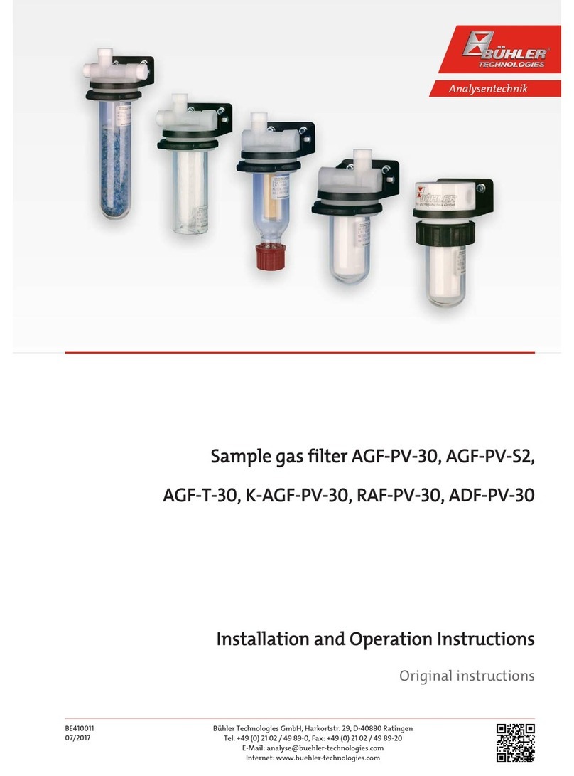
Sample Gas Coalescing Filter K-AGF-
VA-350
3 Use in explosive atmosphere areas
Intended Use
Filters K-AGF-VA-350 and AGF-VA-350 may be used in explosive atmosphere areas zone 1 and 2. Explosion classes IIA, IIB and IIC
are approved. The filter has no innate ignition source and does not fall under Directive 2014/34/EU and therefore does not bear
the CE mark.
II 2/2G c IIC TX X, -5°C <Tamb< +60 °C
The ambient temperatures must not be below -5°C or above 60°C.
The highest surface temperature is directly affected by the temperature of the medium introduced. The medium introduced
must not exceed the maximum temperature of 100°C. If necessary, a temperature monitor should be installed.
Depending on the process conditions, pressure- or flow sensors may be required for continuous monitoring. If the process holds
a risk of flame propagation a flame arrestor must be installed.
The approved explosion class of the inner zone varies by the filter element used. See chapter AGF-VA-350 [> page11] and K-
AGF-VA-350 [> page12]to match filter element options with explosion classes.
Safety instructions
The following safety notices must absolutely be followed when operating the filter in an area with explosive atmosphere. Fail-
ure to do so can result in an explosion hazard.
– Only perform installation-, removal- and maintenance work in non-explosive atmosphere.
– Protect filter from mechanical impact. If necessary, install a cover which withstands at least 4 joule.
– Protect filter from vibration, or avoid vibration. If necessary, mechanically brace supply and discharge lines.
– Observe all limits, operating parameters, etc. specified in these operating instructions and the data sheet.
– Maintenance and cleaning instructions must be followed.
– When used with moist gasses, a condensate separator must be installed. Moist gasses can clog pores in the filter. Gas pres-
sure building up can result in an impermissible temperature rise.
– Observe the grade of filtration of the fine mesh filter and if necessary install a pre-filtration to ensure larger solid particles do
not clog the filter prematurely.
– Observe the durability list in this document. Only use media compatible with the filter materials.
– Do not repair the filter. Damaged filter components must be replaced.
– Do not paint, laminate or otherwise coat the filters.
– Observe the applicable constructor regulations, e.g. EN 60079-14, for installation and mounting.
– All metallic parts of the filter must be connected to an earth potential. The resistance of a continuity test must not exceed 1
MΩ (1*106 Ω).
– The sealing materials, e.g. Teflon tape, must be conductive so all parts of the filter are earthed. If necessary, install an earth
bridge.
Operation and Control
DANGER Risk of explosive gasses leaking and crossing zones
Check the filter is tight prior to operation.
Inadequately sealed filters can leak. Gas may leak or the ambient atmosphere be drawn
in. Use a suitable method for the leakage test, appropriate for the application.
Service
Please note the following instructions. Failure to do so may result in explosive gasses escaping and crossing zones.
– Check the filter is tight after any maintenance and the intervals specified in the maintenance schedule. Inadequately sealed
filters can leak. Gas may leak or the ambient atmosphere be drawn in. Use a suitable method for the leakage test, appropri-
ate for the application.
– There must be no internal or external Ex atmosphere when performing maintenance. If necessary, flush the filter with inert
gas. Switch off pumps on the gas circuit and close supply and discharge lines.
5Bühler Technologies GmbHBE410013 ◦ 06/2019


