B-K Medical Flex Focus 200 User manual


1202
General Information
BI1202-E
1-1
Section 1
GENERAL INFORMATION
CONTENTS PAGE
1Safety Aspects...........................................................................................................................................2
1.1 Terms and Symbols used......................................................................................................................2
1.2 WARNINGS and CAUTIONS: ..............................................................................................................3
2System Overview.......................................................................................................................................4
2.1 System Configuration.............................................................................................................................4
2.2 Modules..................................................................................................................................................7
3Connectors...............................................................................................................................................14
4Revision System......................................................................................................................................15
5Special Tools and Equipment ................................................................................................................15
5.1 Checking Procedure (Section 3)..........................................................................................................15
5.2 Troubleshooting (Section 4).................................................................................................................15
5.3 Adjustment Procedure (Section 5).......................................................................................................16
5.4 Mechanical Parts (Section 6)...............................................................................................................16
5.5 Preventative Maintenance (Section 7).................................................................................................16
5.6 Electrical Safety Test ...........................................................................................................................16

General Information
1202
1-2
BI1202-E
1 Safety Aspects The 1202 System complies with:
EN/IEC 60601-1 Class I and Internal powered
EN 60601-2-37
UL60601-1
CSAC22.2 No.601.1.
The 1202 System is classified as follows:
Array Input Module: Type B (Body)
Single-element Transducer Module: Type B (Body)
1.1 Terms and Symbols used
Throughout this manual the following terms are used to indicate a situation where safety
precautions are required:
"WARNING": Indicates a situation involving risk of injury or loss of life to personnel or
patient.
"CAUTION": Indicates a situation involving risk of damage to the instrument or other
equipment connected.
Symbol
Name
Description
ATTENTION
Consult ACCOMPANYING User Guide (BB1946) when this sign is
encountered on the instrument, to avoid reducing its safety
Potential
Equalisation
Terminal connected to the chassis. Should be connected to
corresponding terminals on other equipment to eliminate potential
differences.
Protective
Earth
Additional Protective Earth
Type CF
CF: Isolated from earth. Maximum Patient Leakage Current under:
Normal Condition 10A, Single Fault Condition 50A
Type BF
BF: Isolated from earth. Maximum Patient Leakage Current under:
Normal Condition 100A, Single Fault Condition 500A
Type BF
BF, DEFIBRILLATOR-PROOF
Type B
B: Maximum Patient Leakage Current under: Normal Condition
100A, Single Fault Condition 500A
IP57
SEALING
Dust and immersion protected according to IEC Publication 529
Stand-by
Push button for switching the scanner from stand-by to active.
(The power supply cord is the means of separation from the main
power supply.)
Off
Main power supply off
On
Main power supply on
Non-ionising
radiation
Ultrasound Scanner emits acoustic radiation
STERILE
Device is in a sterile condition
Table 1. IEC safety symbols

1202
General Information
BI1202-E
1-3
1.2 WARNINGS and CAUTIONS:
For your own and others safety please read the following carefully:
Warnings:
Opening the instrument can expose live parts.
Any work done on the open instrument with power on must only be done by B-K
Medical or their authorised representatives, who are aware of the hazards
involved.
Any repair on the 1202 must be followed by an electrical safety test to verify a
continuous safe operation of the system.
Only the original mains cable must be used NEVER USE EXTENSION CABLES!!
The 1202 contains a Lithium battery. Under no circumstances must this battery be
removed or replaced by the user as there is danger of explosion.
Personal Safety:
Be aware that there may be a risk of infection due to contaminated equipment,
especially puncture guides/needles and transducers. The following precautions should
be taken:
At the hospital ask the staff to sterilise transducers and puncture guides before
receipt. Consoles must be disinfected as recommended in the User Guide before
any repair.
When working with possible infected equipment, use gloves especially if you have
open wounds or scratches.
Possible infected equipment must be sterilised before handed over to customers.
Follow the recommendations in the Transducer User Guide.
Always wash your hands after working with the equipment.
If you scratch yourself on contaminated equipment you should immediately contact
the hospital staff or see a doctor.
Cautions:
Always use correct fuses.
Switch off all equipment before connecting or disconnecting their interfaces.
Failure to do so could damage the equipment.
The power supply cord is the means of connecting the 1202 from the main power
supply.
The 1202 does not have a safety transformer. Ensure that external equipment
connected to the 1202 meets the required electrical safety standards.
General Information
1202
1-4
BI1202-E
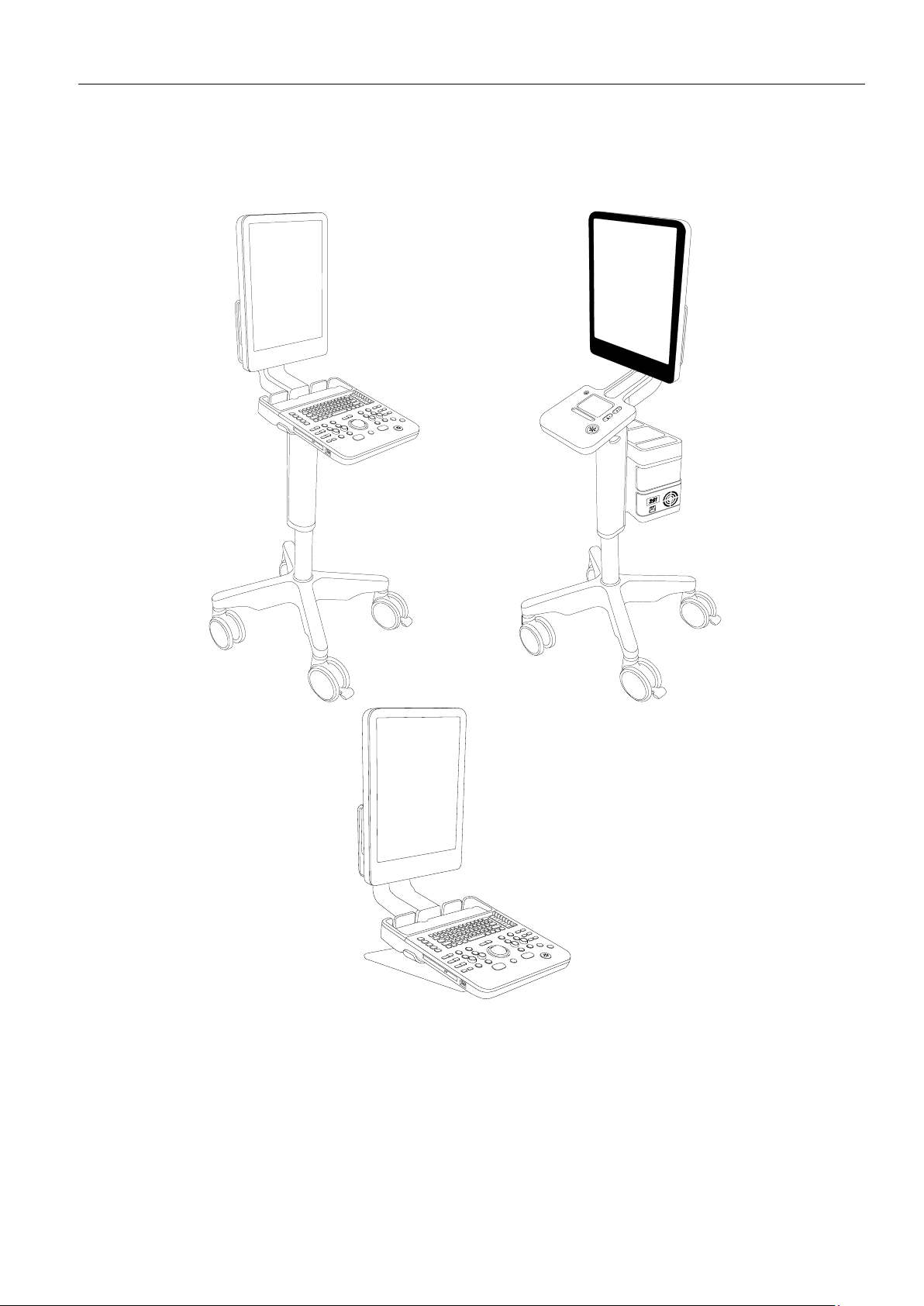
2 System Overview
2.1 System Configuration
Example of assembled 1202 systems
1202
General Information
BI1202-E
1-5
A Flex Focus 1202 system consists of a scanning unit and a dock
2
.
The Scanning unit exists in the following main versions:
1202-2 Flex Focus 200
1202-6 Flex Focus 200 (for Dornier & EDAP)
1202-7 Flex Focus 200 Surgery
1202-1 Flex Focus 400
1202-4 Flex Focus 400 Anesthesia
1202-5 Flex Focus 400 Physio (DK only)
1202-8 Flex Focus 400 MSK (US only)
1202-9 Flex Focus 500
1202-3 Flex Focus 700
1202-10 Flex Focus 800
1202-11 Flex Focus 800 (Histoscan)
2
Further (and latest) information about available features and options can be found in the Product Data Sheet (BP0132)

General Information
1202
1-6
BI1202-E
The Dock exists in seven versions:
Mobile Keyboard Dock UA1210
Mobile Touch Dock UA1810
Keyboard Table Dock UA1283
Keyboard Wall Dock UA1211
Touch Wall Dock UA1811
Mobile Keyboard Dock with Battery UA1214
Mobile Touch Dock with Battery UA1814

1202
General Information
BI1202-E
1-7
2.2 Modules
1202-2
Flex Focus 200
1202-7
Flex Focus 200
Surgery
1202-6
Flex Focus 200
(for Dornier &
EDAP)
1202-1
Flex Focus 400
1202-4
Flex Focus 400
Anesthesia
1202-5
Flex Focus 400
Physio (DK only)
1202-8 Flex Focus
400 MSK (US only)
1202-9 Flex Focus
500
Touch screen
N/A
N/A
N/A
N/A
Flat Panel
ZN0051
ZN0051
ZN0051
ZN0051
TMUX
assembly
ZN1231
ZN1231
ZN1230
ZN1233
-TMUX board
ZE0825
ZE0825
ZE0825
ZE0825
-I/O board
ZD0793
ZD0793
ZD0793
ZD0793
-Single Con
N/A
N/A
ZH0810
ZH0810
-Harddsik
UL0046
UL0046
UL0046
UL0050
Coreboard
assembly
ZN1222
ZN1220
ZN1223
ZN1221
-Coreboard
ZD0790
ZD0790
ZD0790
ZD0790
-ETX
ZD0800
ZD0799
ZD0799
ZD0799
-PMC
N/A
N/A
ZD0802
ZD0797
Front-end
ZE0824
ZE0824
ZE0824
ZE0824
1202-3
Flex Focus 700
1202-10
Flex Focus 800
1202-11
Flex Focus 800
(Histoscan)
Touch screen
NP0025
NP0025
NP0025
Flat Panel
ZN0051
ZN0051
ZN0051
TMUX
assembly
ZN1233
ZN1233
ZN1230
-TMUX board
ZE0825
ZE0825
ZE0825
-I/O board
ZD0793
ZD0793
ZD0793
-Single Con
ZH0810
ZH0810
ZH0810
-Harddsik
UL0050
UL0050
UL0050
Coreboard
assembly
ZN1221
ZN1221
ZN1225
-Coreboard
ZD0790
ZD0790
ZD0805
-ETX
ZD0799
ZD0799
ZD0799
-PMC
ZD0797
ZD0797
ZD0797
Front-end
ZE0824
ZE0824
ZE0824

General Information
1202
1-8
BI1202-E
1202 Scanning unit
TMUX assemblies
Part Name
Part
Number
Picture
TMUX board
ZE0825
I/O Module board
ZD0793
Single Conn.
Interconnect
ZH0810
Hard Disk (SATA) with
SW
UL0046
Hard Disk (SATA) with
SW
UL0048

1202
General Information
BI1202-E
1-9
Core board assemblies
Part
Name
Part
Number
Core
board
ZD0790
ETX
module
ZD0799/
ZD0800
PMC
module
ZD0797
Front
End
board
ZE0824
General Information
1202
1-10
BI1202-E
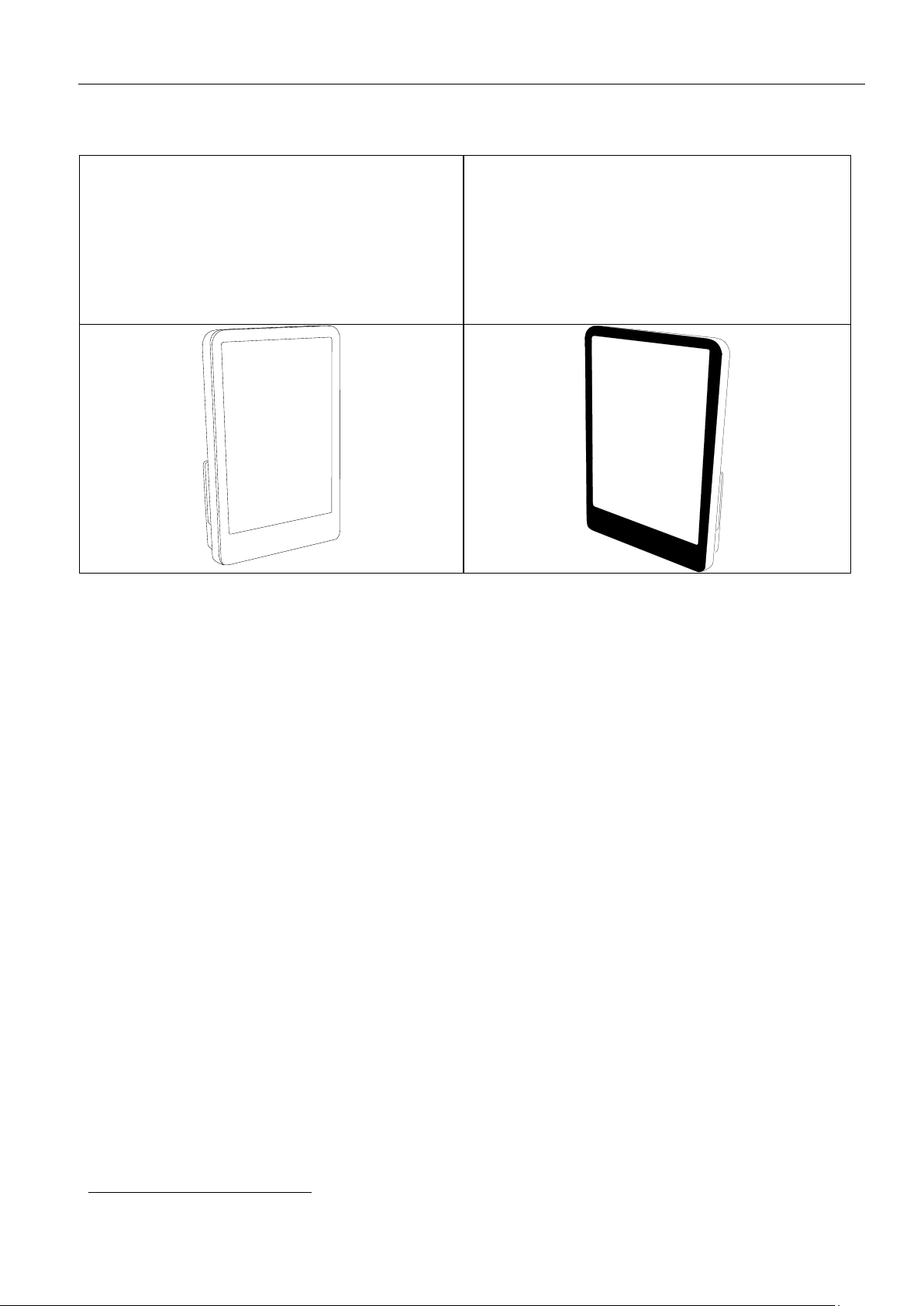
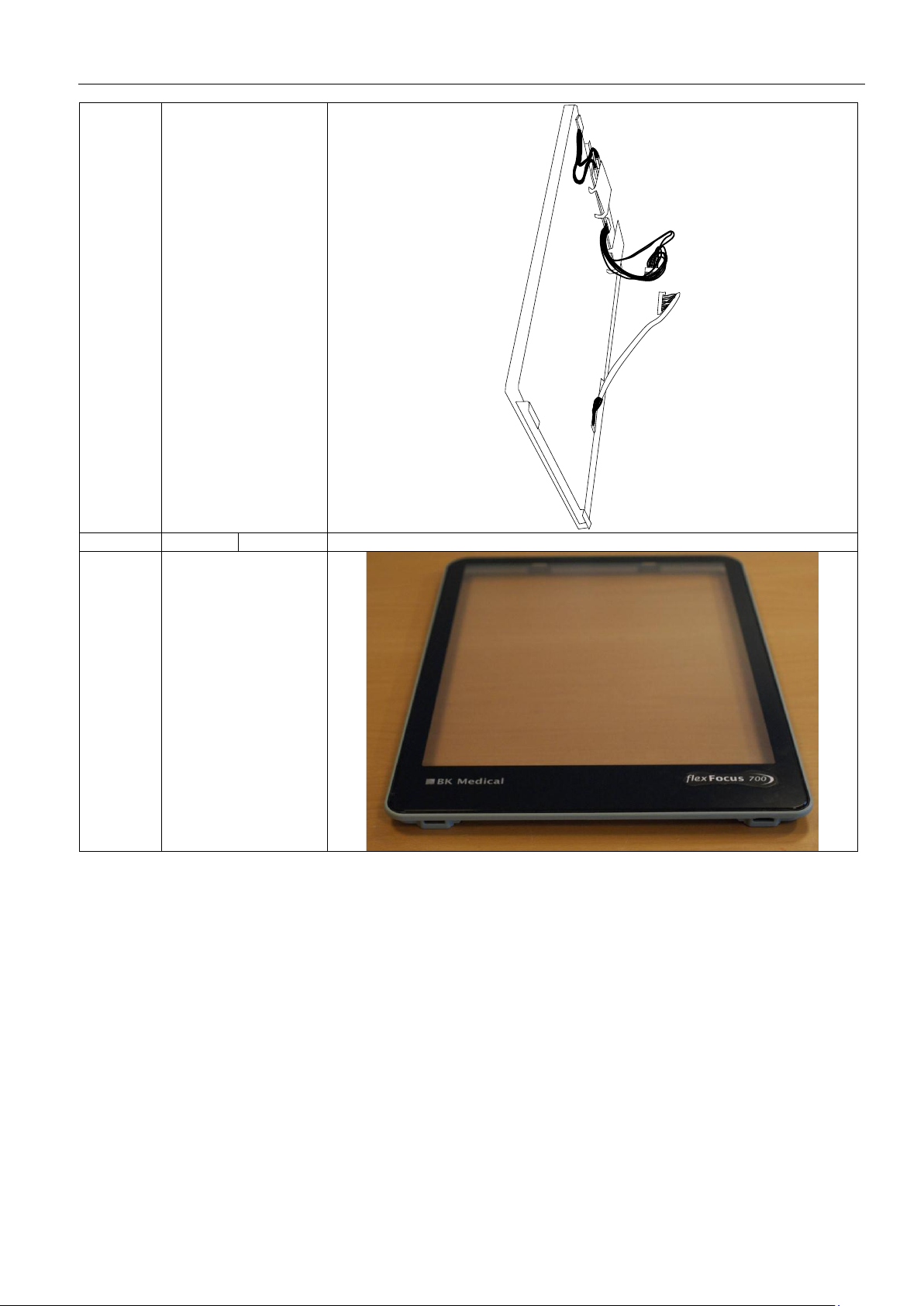
Flat
Panel
assembly
ZN0051
Front
with
touch
screen
NP0025

1202
General Information
BI1202-E
1-11
UA1210
UA1211
UA1283
UA1810
UA1811
UA1214
UA1814
Track Pad
N/A
ZN9049
N/A
ZN9049
Keyboard
NP0182
N/A
NP0182
N/A
Keyboard
Controller
ZH0807
ZH0816
ZH0536
ZH0807
ZH0816
ZH0536
DVD drive
UL0011
UL0013
N/A
UL0011
UL0013
N/A
Power Supply
ZN0360
ZG0360
ZN0360
ZG0360
I/O Connector
ZH0802
ZH0802
ZH0802
ZH0802
DVI Connector
ZH0811
ZH0811
ZH0811
ZH0811
Docking board
ZH0666
ZH0666
ZH0666
ZH0666
Battery Unit
N/A
N/A
ZN1214-S
ZN1214-S
Docking Units
Keyboard
NP0182
Keyboard
Control
ZH0807
ZH0816

General Information
1202
1-12
BI1202-E
Power Supply
Not in UA1214
ZN0360
I/O Connector
board
ZH0802
DVI
Connector
Board
ZH0811
Docking board
ZH0666

1202
General Information
BI1202-E
1-13
DVD Drive
(optional)
UL0011
UL0013
Track pad
ZN9049
Trackpad
Controler
ZH0536

General Information
1202
1-14
BI1202-E
3 Connectors
Video out
USB
Audio out
LAN
/DICOM
DVI-I out
Video in
Note ! Whether a input/output is active depends on the
configuration of the scanner
Mains input on standard unit
Mains input on unit with Battery Support
Fuses
Mains
input
Mains
output for
Printer
Fuses
Mains
input

1202
General Information
BI1202-E
1-15
4 Revision System
All PC Boards in the 1202 are described by the board name, Type number, Revision code
(ID) and PCB Version.
The name of the board indicates the function of the board, for example the Core Board.
The name of the board is changed only if the function of the board changes.
Bar Code Label
The Part number of the board, for example ZD0790, is the order number of the board.
The number is changed if the modification of the existing PCB is found to be too
extensive.
The serial number of the board is a unique number used for tracking purposes.
The revision code (ABCDEFGH.......) is related to the modifications made on the board.
The revision letter is marked when modifications are made. When boards are ordered
from the B-K Medical stock it is important that the serial number of the scanner is stated.
The serial number ensures that the correct revision is shipped.
The PCB version (number e.g. 3) is printed on the circuit board.
The Version and Revision code can be read electronically.
Note! Some modules (assemblies) that consist of a number of PCB’s does only have a
Part No. and a serial number but no revision. E.g. Core board assembly - ZN1221
consists of ZD0790, ZD0799 and ZD0797.
5 Special Tools and Equipment
The tools and equipment listed below does not include standard tools and commonly used
equipment.
5.1 Checking Procedure (Section 3)
Blank CD/DVD (for testing DVD Drive) (optional)
5.2 Troubleshooting (Section 4)
Accessing BIOS (for loading new image on Harddisk drive)
USB keyboard
|| | || || ||| | | | | | ||| |||| |
ZD0790 001 837 B-K Medical
FGHIJKLMNOPQRSTUVXY
Part number
Serial Number
Revision level
in this case: E
ABCDE

General Information
1202
1-16
BI1202-E
5.3 Adjustment Procedure (Section 5)
For adjusting the trackball:
Trackball Adjustment Key QA0228
5.4 Mechanical Parts (Section 6)
Static Control Service Kit, type 3M 8501 (WQ 0969) or similar.
(when handling the static sensitive PCB’s).
Torx keys #8, #10, #20
2,5 mm Hex key
Philips screwdriver
5.5 Preventative Maintenance (Section 7)
Equipment necessary to perform the Preventative Maintenance is the equipment used
in the Checking Procedure and Electrical Safety Test.
5.6 Electrical Safety Test
Testers required:
Safety Tester
HV Tester
High Voltage test plugs/adopters required:
WB 1275 HV test adaptor for type BF Transducers
WJ 0246 HV Test Plug for Mains
Electrical Safety Test Record (Enclosed)
This manual suits for next models
6
Table of contents


