Charge on.
BlinkCharging.com Page 7 of 52
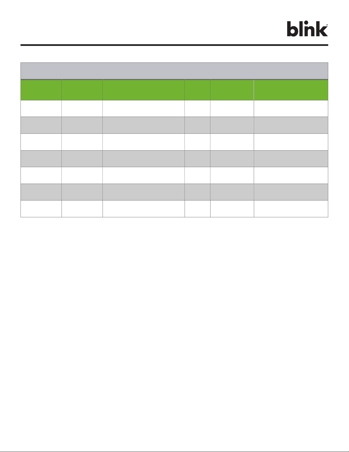
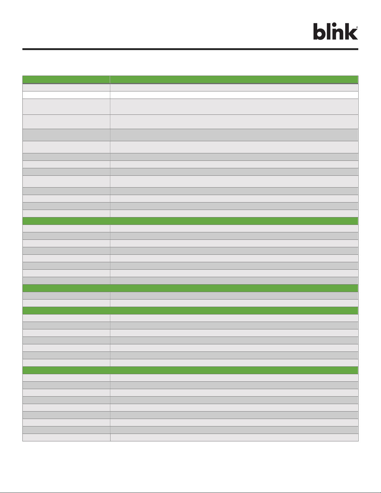
4. PRODUCT SPECIFICATIONS
POWER SPECIFICATIONS HQ 200 Smart
Maximum Power 12 kW
Standby Power < 3.6 W
Output Power (208 V) NEMA 14-50P: 2.5, 3.3, 4.9, 6.6, 8.3 kW
Hardwired: 2.5, 3.3, 4.9, 6.6, 8.3, 9.9, 10.4 kW
Output Power (240 V) NEMA 14-50P: 2.9, 3.8, 5.8, 7.7, 9.6 kW
Hardwired: 2.9, 3.8, 5.8, 7.7, 9.6, 11.5, 12 kW
Output Amperage
Hardwired: 12, 16, 24, 32, 40, 48, 50 A
Circuit Breaker Options
Hardwired: 15, 20, 30, 40, 50, 60, 70 A
Voltage 208/240 VAC
Voltage Range 180 to 264 VAC
Frequency 50, 60 Hz
Input Wiring Type
Hardwired (Optional)
Input Wiring Scheme L1, L2, PE
Cold-Load Pickup Randomized delay between 120 and 720 sec. before charge resumes after a power failure.
Power Measurement Accuracy Embedded meter with a ±1% accuracy at the nominal input.
Surge Protection Up to 6 kV at 3,000 A
FUNCTIONAL SPECIFICATIONS
Charge Connector Type SAE J1772, Lockable (up to 0.24” or 5mm Shackle Diameter)
Charge Cable Length 23ft. (7.01m)
Demand Response Yes
Status Indicator Status & WLAN LEDs, Audio
User Interface Mobile Application
Digital Assistants Apple Siri, Google Assistant, Amazon Alexa
Access Control None
Local Load Management Client
NETWORK SPECIFICATIONS
Wireless Local Area Network (LAN) 2.4 and 5 GHz Wi-Fi (802.11 b/g/n/ac)
Wide Area Network (WAN) None
SAFETY & COMPLIANCE SPECIFICATIONS
Ground Fault Detection CCID20, 20 mA per UL 2231, Automatic Reset Feature and Manual Reset Feature
Ground Monitor Ground Monitor per UL 2231
Safety Compliance UL and cUL, NEC Article 625, RoHS
Protection Over-Voltage (OVP), Under-Voltage (UVP), Over-Current (OCP), Over-Temperature (OTP), and Short-Circuit Protection
EMC Compliance FCC Part 15B, Industry Canada (IC), Norma Oficial Mexicana (NOM)
ADA Compliance Yes
ENERGY STAR Certified Yes
OPERATIONAL SPECIFICATIONS
Mounting Type Wall Mount
Enclosure Rating NEMA Type 3R Indoor/Outdoor
Operating Temperature Up to 40 A: -30°C to +50°C (-22°F to +122°F), At 50A: -30°C to +45°C (-22°F to +113°F)
Storage Temperature -40°C to +80°C (-40°F to +176°F)
Operating Humidity 5 to 95 % Relative Humidity, Non-Condensing
Charger Dimensions 11.65”H × 8.91”W × 4.02”D (296mm H x 226.2mm W x 102.2mm D)
Package Dimensions 18.15”H x 14.80”W x 11.42”D (461mm H x 376mm W x 290mm D)
Charger Weight (Unpackaged) 20.94lbs. (9.5kg)
Charger Weight (Packaged) 23.15lbs. (10.5kg)
Blink reserves the right to alter product offerings and specs at any time without notice and is not responsible for typographical or graphical errors that may appear in this document.
Table 2. Product Specifications