B-Link MQ 200 User manual
BlinkCharging.com
INSTRUCTION MANUAL
Blink MQ 200 – Level 2 AC EVSE
Version 1.0

Charge on.
BlinkCharging.com Page 2 of 56
© 2022 by Blink Charging Co. Its Affiliates and Subsidiaries (“Blink”)
No part of the contents of this document may be reproduced or transmitted in any form or by any means without the express
written permission of Blink.The contents of this document have been verified by the manufacturer to be consistent with the
described components; however, inconsistencies sometimes occur. Such inconsistencies should be brought to the attention
of a Blink representative. Changes to this manual may be made at any time without notice.
Disclaimer of Consequential Damages
Blink is not responsible for the use or application by any person of the materials in this manual. Blink is not responsible for
damages, either direct or consequential, arising out of or relating to the use or application of these materials.
Certain sections of this manual are meant as a guide for professional electricians. The manual contains general
guidelines and may not provide instructions for your specific situation. Do not attempt installation if you lack the
knowledge and understanding required for the installation, otherwise personal injury and/or death as well as
property damage or loss could occur.
Electricity is dangerous and can cause personal injury or death as well as other property loss or damage if not
used or constructed properly. If you have any doubts whatsoever about performing the installation of the
equipment, please do the smart thing and hire a licensed electrician to perform the work for you.
Never work with live voltage. Always disconnect the power source before working with electrical circuits.
When performing the installation, please read and follow this manual. Additionally, always follow your local
electrical code and requirements which are specific to local areas.
Notice
Changes or modifications not expressly approved by the party responsible for compliance could void the user’s authority to
operate the equipment.
Blink, Blink Network, and the Blink logo are registered trademarks of Blink.
SAE J1772™ is a trademark of SAE International®

Charge on.
BlinkCharging.com Page 3 of 56
Table of Contents
1. IMPORTANT SAFETY INSTRUCTIONS............................................................................................. 4
2. INTRODUCTION........................................................................................................................... 6
3. PRODUCT OVERVIEW................................................................................................................... 6
4. PRODUCT SPECIFICATIONS........................................................................................................... 7
5. PRE-INSTALLATION INSTRUCTIONS .............................................................................................. 8
5.1. SAFETY AND GROUNDING.............................................................................................................................8
5.2. CONDUIT &BREAKER SIZE GUIDE ....................................................................................................................9
6. INSTALLATION INSTRUCTIONS ................................................................................................... 10
6.1. TOOLS REQUIRED FOR INSTALLATION...............................................................................................................10
6.2. PARTS REQUIRED FOR INSTALLATION................................................................................................................10
6.3. TERMINAL,WIRE SIZE,TEMPERATURE ..............................................................................................................10
6.4. PRODUCT INSTALLATION ..............................................................................................................................11
7. GETTING STARTED ..................................................................................................................... 16
7.1. BROWSER ACCESS ....................................................................................................................................16
7.2. WEB PAGE OVERVIEW ...............................................................................................................................17
7.3. CONFIGURATION ......................................................................................................................................20
7.4. MAINTENANCE.........................................................................................................................................38
7.5. LLM STATUS.............................................................................................................................................39
7.6. SECURITY ................................................................................................................................................49
8. DISPLAY.................................................................................................................................... 50
8.1. CHARGING STATE DISPLAY...........................................................................................................................50
9. OPERATIONS............................................................................................................................. 51
9.1. CHARGING STATUS INDICATORS ...................................................................................................................51
9.2. AUTHORIZATION .......................................................................................................................................51
9.3. START CHARGING .....................................................................................................................................52
9.4. STOP CHARGING ......................................................................................................................................53
10. GENERAL CARE.......................................................................................................................... 54
11. SUPPLEMENTAL INFORMATION.................................................................................................. 55
11.1. ELECTRICAL SERVICE WIRING (240V SPLIT-PHASE SYSTEM (RESIDENTIAL)) ...............................................................55
11.2. THREE-PHASE 208 VWYE-CONNECTED .......................................................................................................55
11.3. THREE-PHASE 240 VDELTA-CONNECTED......................................................................................................56
12. CUSTOMER SUPPORT................................................................................................................. 56
Charge on.
BlinkCharging.com Page 4 of 56
SAVE THESE INSTRUCTIONS
1. IMPORTANT SAFETY INSTRUCTIONS
Before installing or using the Blink Charging Co. Its Affiliates and Subsidiaries (“Blink”) (Blink) electric vehicle
supply equipment (EVSE), read all these instructions, paying particular attention to any WARNING and CAUTION markings
in this document and on the Blink Product. You should also review any instructions included with your electric vehicle (EV) as
they pertain to vehicle charging.The following symbols and associated instructions are used throughout this document and
relate to action necessary to avoid hazards.
Legend
WARNING
Risk of personal injury
WARNING: RISK OF ELECTRIC SHOCK
Risk of electric shock
WARNING: RISK OF FIRE
Risk of fire
CAUTION
Risk of damage to the equipment
• This product should be installed only by a qualified approved technician.
• Blink is not responsible for physical injury, damage to property or equipment caused by the installation of this
device.
• A device employing pressure terminal connectors for field wiring connections shall be provided with instructions
specifying a range of values or a nominal value of tightening torque to be applied to the clamping screws of the
terminal connectors.
• Make sure that the materials used, and the installation procedures follow local building codes and safety
standards.
• The information provided in this manual in no way exempts the user of responsibility to follow all applicable codes
or safety standards.
• Review this manual carefully and consult with a licensed contractor, licensed electrician, or trained installation
expert to make sure of compliance with local building codes and safety standards.
Repair and Maintenance Clause
• Only a licensed contractor, licensed electrician, or trained installation expert is allowed to repair or maintain this
device. It is forbidden for a general user to repair or maintain this device.
• Any repair or maintenance MUST be performed after removing power from this device.
Moving and Storage Instructions
• Store the product at a temperature between -40 and +80 °C.
• Check the product for damage after moving.
• Carry the product by the sides. Do not lift or carry by either the flexible cord or the EV cable, if provided.
Charge on.
BlinkCharging.com Page 5 of 56
FCC Rules and Industry Canada License-Exempt RSS Standard(s)
• This device complies with Part 15 of the FCC Rules. Changes or modifications are not expressly approved by the
manufacturer could void the user’s authority to operate the equipment.
• English: This device complies with Industry Canada license-exempt RSS standard(s). Operation is subject to the
following two conditions: (1) this device may not cause interference, and (2) this device must accept any
interference, including interference that may cause undesired operation of the device.
• French: Le présent appareil est conforme aux CNR d’Industrie Canada applicables aux appareils radio exempts
de licence. ‘exploitation est autorisée aux deux conditions suivantes: (1) l’appareil ne doit pas produire de
brouillage, et (2) l’utilisateur de l’appareil doit accepter tout brouillage radioélectrique subi, même si le brouillage
est susceptible d’en compromettre le fonctionnement.
WARNING: RISK OF ELECTRIC SHOCK
Basic precautions should always be followed when using electrical products, including the following:
• Read all the instructions before using this product.
• This device should be supervised when used around children.
• Do not put fingers into the EV connector.
• Do not use this product if the flexible power cord or EV cable is frayed, has broken insulation, or any
other signs of damage.
• Do not use this product if the enclosure or the EV connector is broken, cracked, open, or shows any
other indication of damage.
WARNING: RISK OF ELECTRIC SHOCK
Improper connection of the equipment grounding conductor can result in a risk of electric shock. Check with a
qualified electrician or serviceman if you are in doubt as to whether the product is properly grounded.
WARNING: RISK OF ELECTRIC SHOCK
• Do not touch live electrical parts.
• Incorrect connections may cause electric shock.
WARNING
This equipment is intended only for charging vehicles that do not require ventilation during charging. Please refer
to your vehicle’s owner’s manual to determine ventilation requirements.
WARNING
Do not use extender cables to increase the length of the charging cable. The maximum length is limited to 25
feet by the National Fire Protection Agency.
WARNING: RISK OF FIRE
To reduce the risk of fire, connect only to a circuit provided with Model HQW2-50C-W1-N1-N-23, HQW2-50C-
N1-N1-N-23, HQW2-50C-W1-N2-N-23-D for 50 A; Model MQW2-50C-M2-R1-N-23, HQW2-50C-W1-N1-N-
23, HQW2-50C-N1-N1-N-23, MQW2-50C-M2-R2-N-23-D, HQW2-50C-W1-N2-N-23-D for 62.5 A amperes
maximum branch circuit overcurrent protection in accordance with the National Electrical Code, ANSI/NFPA 70
and the Canadian Electrical Code, Part I, C22.1.
General Conventions
The use of the word “Note:”indicates additional information that is relevant to the current process or procedure.
Charge on.
BlinkCharging.com Page 6 of 56
2. INTRODUCTION
This INSTRUCTION MANUAL describes how to properly install the Blink MQ 200 – Level 2 AC EVSE (Blink
Product). Contact the Blink Support Center at (888) 998.2546 for troubleshooting assistance and
additional technical questions.
Unauthorized modification of the Blink Product voids the manufacturer’s warranty.
The Blink Product specified in this document is design for the North American market to charge plug-in
electric vehicles (PEVs), plug-in hybrid electric vehicles (PHEVs), and battery electric vehicles (BEVs). It
provides level 2 AC charging that shortens the charging time for typical EVs, when compared to a Level 1
AC EVSE.
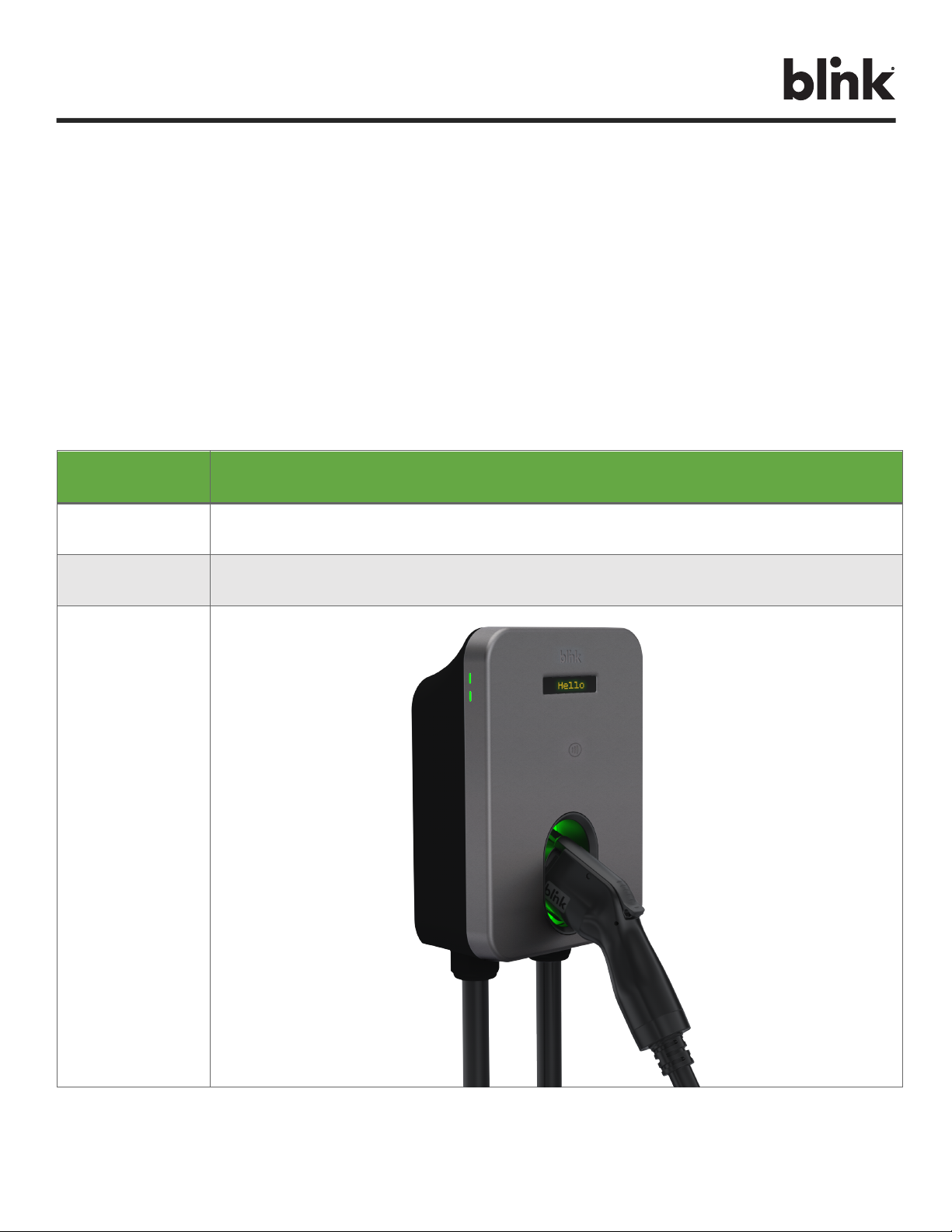
3. PRODUCT OVERVIEW
MODEL NAME
MQ 200
MODEL NUMBER
MQW2-50C-M2-R1-N-23
MQW2-50C-M2-R2-N-23-D
PART NUMBER
01-0202
01-0203
PRODUCT VIEW
Table 1. Product Overview

Charge on.
BlinkCharging.com Page 7 of 56
4. PRODUCT SPECIFICATIONS
POWER SPECIFICATIONS
MQ 200
Maximum Power
12 kW
Standby Power
< 3.6 W
Output Power
2.9, 3.8, 5.8, 7.7, 9.6, 11.5, 12 kW
Output Amperage
12, 16, 24, 32, 40, 48, 50 A
Circuit Breaker Options
15, 20, 30, 40, 50, 60, 70 A
Voltage
208/240 VAC
Voltage Range
180 to 264 VAC
Frequency
50, 60 Hz
Input Wiring Type
Hardwired
Input Wiring Scheme
L1, L2, PE
Cold-Load Pickup
Randomized delay between 120 and 720 sec. before charge resumes after a power failure.
Power Measurement Accuracy
Embedded meter with a ±1% accuracy at the nominal input. CTEP
Surge Protection
Up to 6 kV at 3,000 A
FUNCTIONAL SPECIFICATIONS
Charge Connector Type
SAE J1772, Lockable (up to 0.24” or 5mm Shackle Diameter)
Charge Cable Length
23ft. (7.01m)
Demand Response
Yes
Status Indicator
Status & WLAN LEDs, Audio
User Interface
OLED Screen, Mobile Application
Vehicle to Grid Communications
ISO 15118, Plug & Charge
Digital Assistants
Amazon Alexa, Google Assistant, Apple Siri
Access Control
Contactless Reader: RFID Cards: ISO/IEC 14443A/B, ISO/IEC 15693, MIFARE Plus, NFC
Local Load Management
Gateway, Client
NETWORK SPECIFICATIONS
Wireless Local Area Network (LAN)
2.4 and 5 GHz Wi-Fi (802.11 b/g/n/ac)
Wide Area Network (WAN)
Cellular 4G LTE, AGPS, PTCRB
SAFETY & COMPLIANCE SPECIFICATIONS
Ground Fault Detection
CCID20, 20 mA per UL 2231, Automatic Reset Feature and Manual Reset Feature
Ground Monitor
Ground Monitor per UL 2231
Safety Compliance
UL and cUL, NEC Article 625, RoHS
Protection
Over-Voltage (OVP), Under-Voltage (UVP), Over-Current (OCP), Over-Temperature (OTP), and Short-Circuit Protection
EMC Compliance
FCC Part 15B, Industry Canada (IC)
FCC Part 15B, Industry Canada (IC), Norma Oficial Mexicana (NOM)
ADA Compliance
Yes
ENERGY STAR Certified
Yes
OPERATIONAL SPECIFICATIONS
Mounting Type
Wall Mount
Enclosure Rating
NEMA Type 3R Indoor/Outdoor
Operating Temperature
Up to 40 A: -30°C to +50°C (-22°F to +122°F), At 50A: -30°C to +45°C (-22°F to +113°F)
Storage Temperature
-40°C to +80°C (-40°F to +176°F)
Operating Humidity
5 to 95 % Relative Humidity, Non-Condensing
Charger Dimensions
11.65”H ×8.91”W ×4.02”D (296mm H x 226.2mm W x 102.2mm D)
Package Dimensions
18.15”H x 14.80”W x 11.42”D (461mm H x 376mm W x 290mm D)
Charger Weight (Unpackaged)
20.94lbs. (9.5kg)
Charger Weight (Packaged)
23.15lbs. (10.5kg)
Blink reserves the right to alter product offerings and specs at any time without notice and is not responsible for typographical or graphical errors that may appear in this document.
Table 2. Product Specifications

Charge on.
BlinkCharging.com Page 8 of 56
5. PRE-INSTALLATION INSTRUCTIONS
5.1. Safety and Grounding
5.1.1.1. Safety Check
CAUTION: DISCONNECT ELECTRICAL POWER PRIOR TO INSTALLING THE
BLINK CHARGING STATION. FAILURE TO DO SO MAY CAUSE PHYSICAL INJURY
OR DAMAGE TO THE ELECTRICAL SYSTEM AND BLINK PRODUCT.
The Blink Product should be installed only by a licensed contractor, and/or a licensed
electrician in accordance with all applicable state, local and national electrical codes
and standards.
Before installing the Blink Product, review this manual carefully and consult with a
licensed contractor, licensed electrician and trained installation expert to ensure
compliance with local building practices, climate conditions, safety standards, and
state and local codes.
Use appropriate protection when connecting to the main power distribution cable. Use
tools as outlined in the “Tools Required for Installation” section.
5.1.1.2. Grounding Instructions
This product must be connected to a grounded, metal, permanent wiring system; and
an equipment grounding conductor must be run with the circuit conductors and
connected to the equipment grounding terminal or lead on the product.

Charge on.
BlinkCharging.com Page 9 of 56
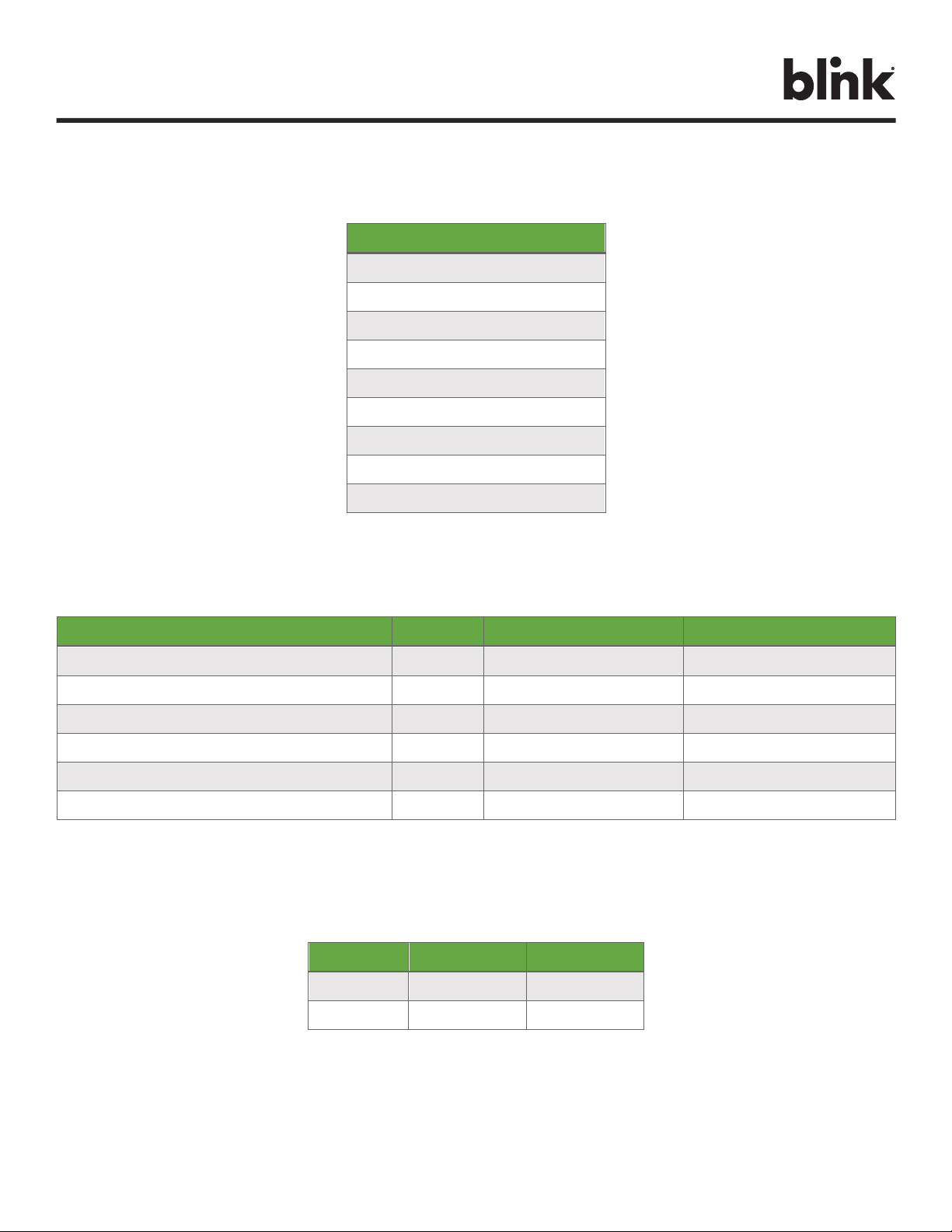
5.2. Conduit & Breaker Size Guide
All Specifications are Per Charging Station or Port
Max. Output
(Charging)
Current
Typical Circuit
Breaker (CB)3
Typical Wire Specs3
Typical
Conduit
Size3
Blink IQ 200
Enclosure Input
Conduit Size
Notes / Assumptions
12A
15A
Two #12AWG Wires (Line)
One #12AWG Wire (Ground)
1/2"
1”
≤150ft. One-Way Distance
≤3% Voltage Drop
16A
20A
Two #10AWG Wires (Line)
One #12AWG Wire (Ground)
3/4"
1”
≤150ft. One-Way Distance
≤3% Voltage Drop
24A
30A
Two #8AWG Wires (Line)
One #10AWG Wire (Ground)
3/4"
1”
≤150ft. One-Way Distance
≤3% Voltage Drop
32A
40A
Two #8AWG Wires (Line)
One #10AWG Wire (Ground)
3/4"
1”
≤150ft. One-Way Distance
≤3% Voltage Drop
40A
50A
Two #6AWG Wires (Line)
One #8AWG Wire (Ground)
3/4"
1”
≤150ft. One-Way Distance
≤3% Voltage Drop
48A
60A
Two #4AWG Wires (Line)
One #8AWG Wire (Ground)
1”
1”
≤150ft. One-Way Distance
≤3% Voltage Drop
50A
70A
Two #4AWG Wires (Line)
One #8AWG Wire (Ground)
1”
1”
≤150ft. One-Way Distance
≤3% Voltage Drop
3Consult with a licensed contractor, licensed electrician, or trained installation expert to ensure compliance with local building codes and safety standards.
Table 3. Conduit and Breaker Size Guide
Charge on.
BlinkCharging.com Page 10 of 56
6. INSTALLATION INSTRUCTIONS
6.1. Tools Required for Installation
Tools
Security Torx T20 Driver
Wire Cutters
Wire Strippers
Torque Wrench
Drill
Drill Bits
Slotted Screwdriver
P3 Phillips Screwdriver
Heat Shrink Tube
Table 4. Tools Required for Installation
6.2. Parts Required for Installation
Part
Quantity
Applicable Models
Notes
MQ 200 Charger 50 A
1
All Product Models
Included
Mounting Bracket
1
All Product Models
Included
Mounting Screws, Wood, 5/16”
2
Commercially Available
Commercially Available
Mounting Anchors, Masonry, 5/16”
4
Commercially Available
Commercially Available
Conduit Fitting, 1”
1
Commercially Available
Commercially Available
Conduit, 1”
As Needed
Commercially Available
Commercially Available
Table 5. Parts Required for Installation
6.3. Terminal, Wire Size, Temperature
Terminal
Wire Size
Temperature
L1/L2
6 AWG
90 °C
PE
10 AWG
90 °C
Table 6. Terminal Information

Charge on.
BlinkCharging.com Page 11 of 56
6.4. Product Installation
STEP 1: Remove front cover screws
STEP 2: Remove the front cover
STEP 3: Remove the installation cover screws
STEP 4: Remove installation cover
Figure 1. Exploded View of MQ 200 Charger
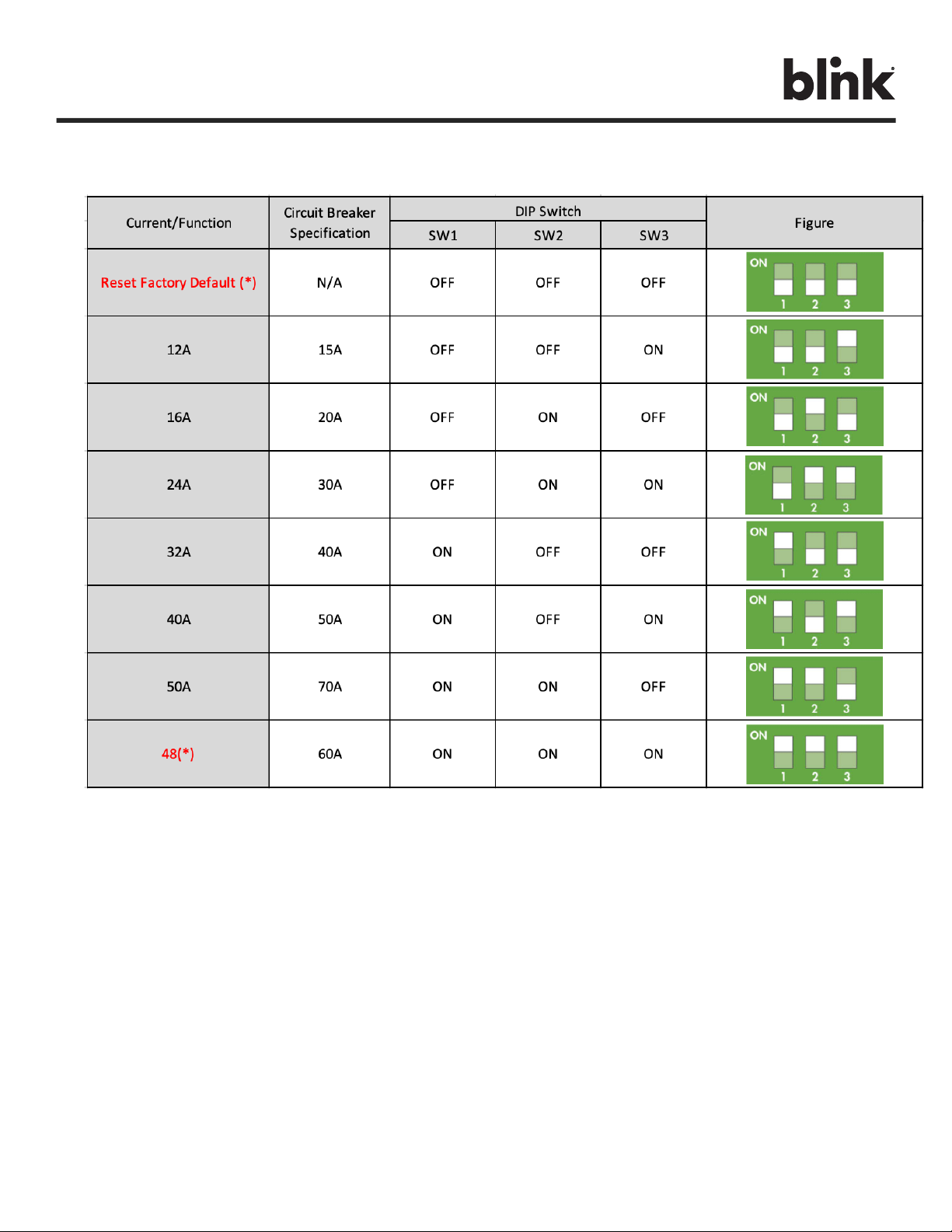
Figure 2. DIP Switch
Charge on.
BlinkCharging.com Page 12 of 56
STEP 5: Set maximum current by configuring the DIP switch using the following table:
Table 7. DIP Switch Configuration
WARNING: Power must remain off before setting or configuring the DIP switch.
* Note: will be available in MP phase.
Charge on.
BlinkCharging.com Page 13 of 56
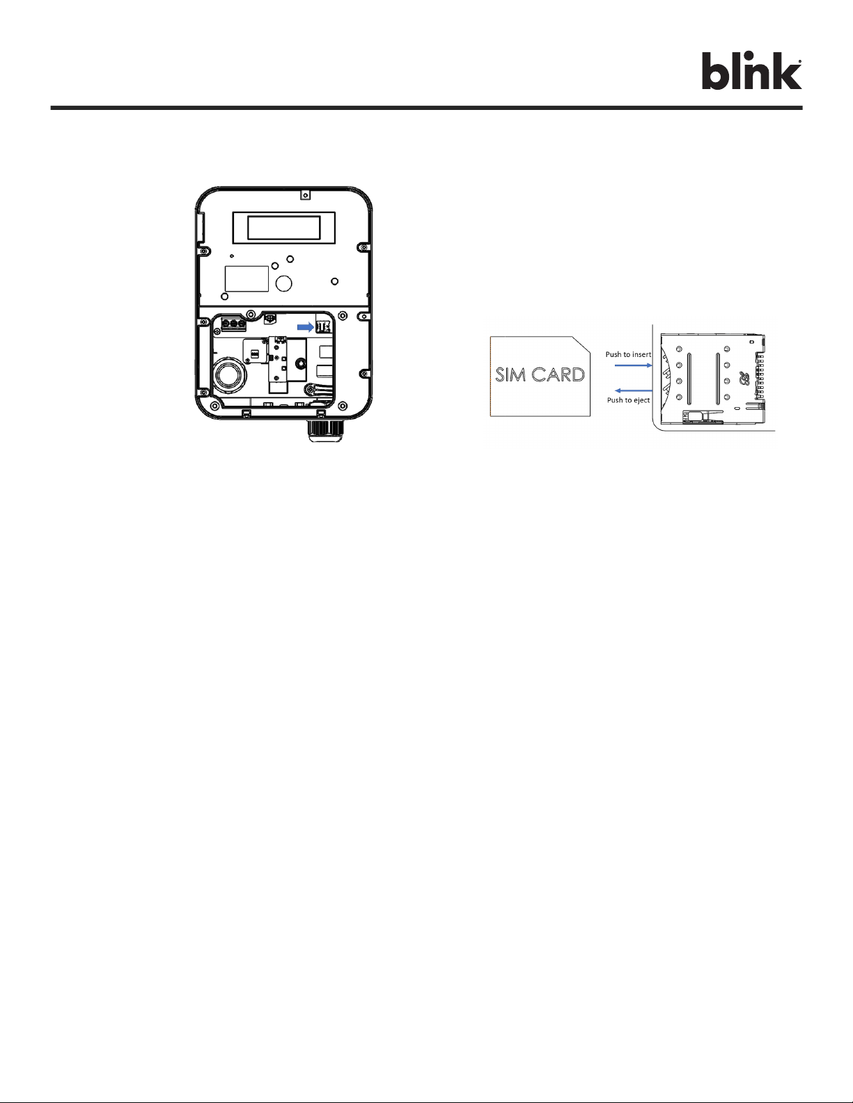
STEP 6: Install SIM card.
Figure 3. SIM Card Location and Installation
STEP 7: Secure the main body mounting bracket to the wall with appropriate screws.
Follow applicable accessibility requirements for the mounting position. The unit shall be stored
or located at a sufficient height above the floor. For an indoor site, it should be not lower than
18” (450 mm) and not higher than 4” (1.2m). For an outdoor site, it should be not lower than
24” (600 mm) and not higher than 4” (1.2m). Refer to Article 625, NEC.
The mounting bracket has six screw holes for wall mounting. If only two screws are used for
mounting, the screws should pass through the middle two screw holes of the mounting bracket.
The other screw holes are reserved for the user.

Charge on.
BlinkCharging.com Page 14 of 56
Figure 4. Fasten Mounting Bracket
A. For masonry walls, use M6 mechanical screws (commercially available).
B. For finished walls supported by wood studs, use #12 self-tapping screws.
C. Please refer to the following torque. The actual torque is according to the wall material.
Screw
Torque
M6
25 kgf.cm min
21.7 lb.-in min
#12
25 kgf.cm min
21.7 lb.-in min
Table 8. Mounting Bracket Torque Values
M6 Screw
ScrewScre
w
Charge on.
BlinkCharging.com Page 15 of 56
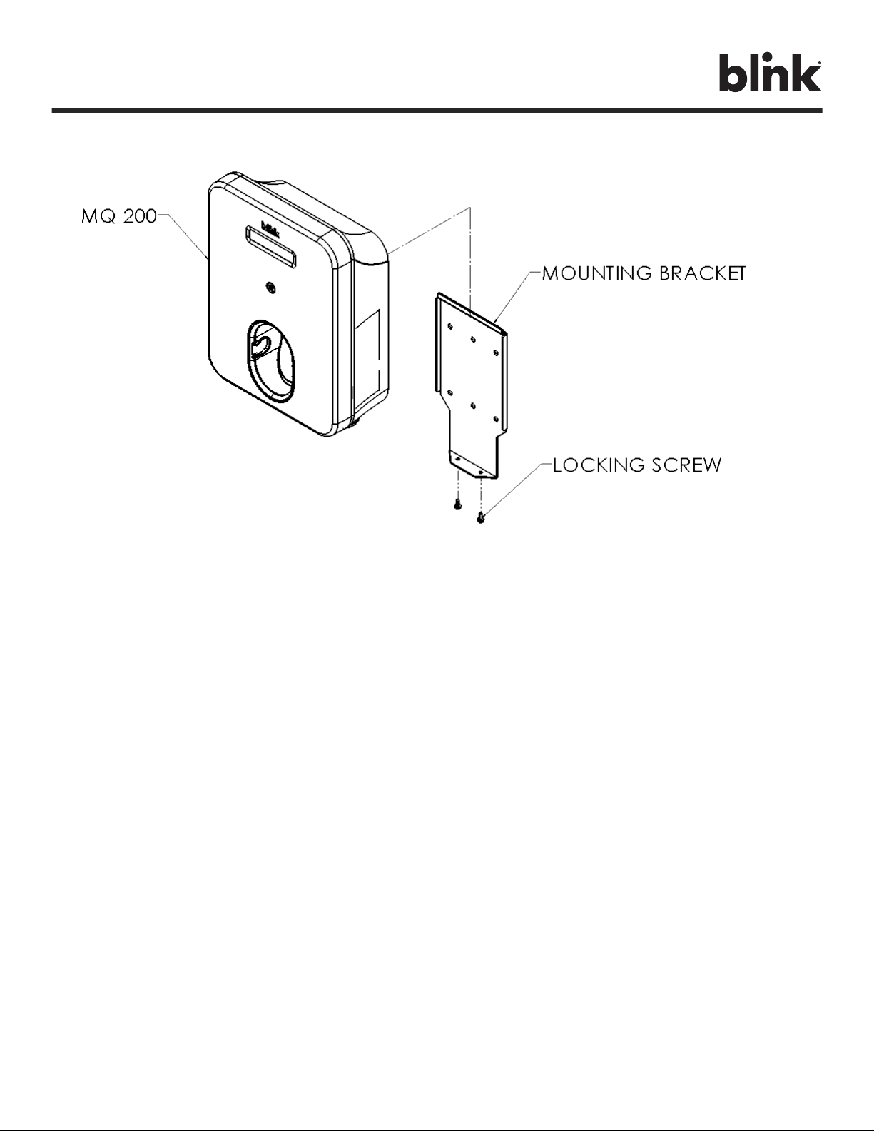
Figure 5. MQ 200 Charger and Mounting Bracket
STEP 8: Hang the product on the mounting bracket.
STEP 9: Slide down the product to rest on the bottom flange.
STEP 10: Install the locking screws (M4 Torx).
STEP 11: Reassemble the Install Cover and Front Cover with M4 screws using 15 kgf.-cm
(12 lb.-in.).
Charge on.
BlinkCharging.com Page 16 of 56
7. Getting Started
7.1. Browser Access
7.1.1. Local Network Setup
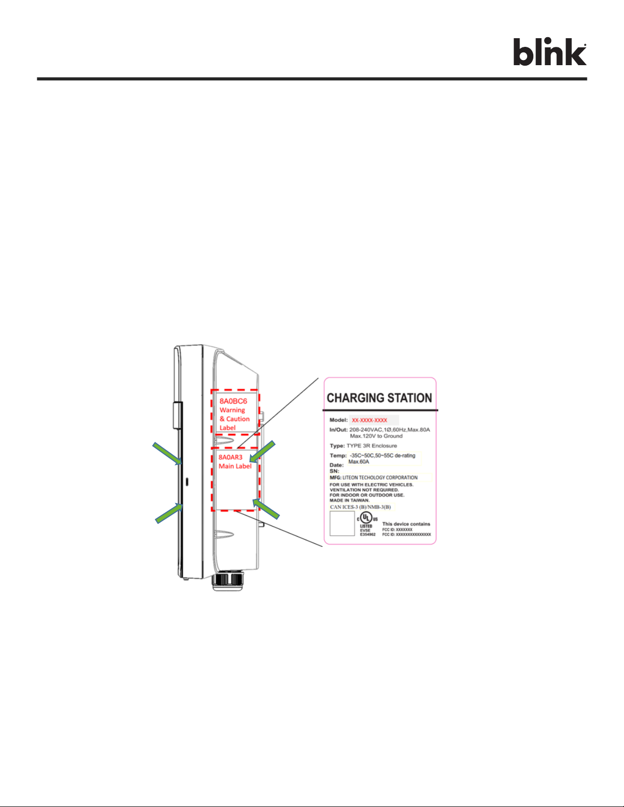
The charger’s factory default network setting is a Wi-Fi Access Point (AP). You can access the charger
by Wi-Fi using a phone or computer. The Wi-Fi network name (SSID) is a number on the label on the
side of the EVSE. Please refer to
Figure. The SSID name is IC80A+SN. The default password is “SN+@IC80A”.
Ex. SN: Ex-1193-1A13-1-1234-2444,
The SSID name is IC80AEx-1193-1A13-1-1234-2444.
The password is Ex-1193-1A13-1-1234-2444@IC80A.
Figure 6. Serial Number Location on Main Label
Charge on.
BlinkCharging.com Page 17 of 56
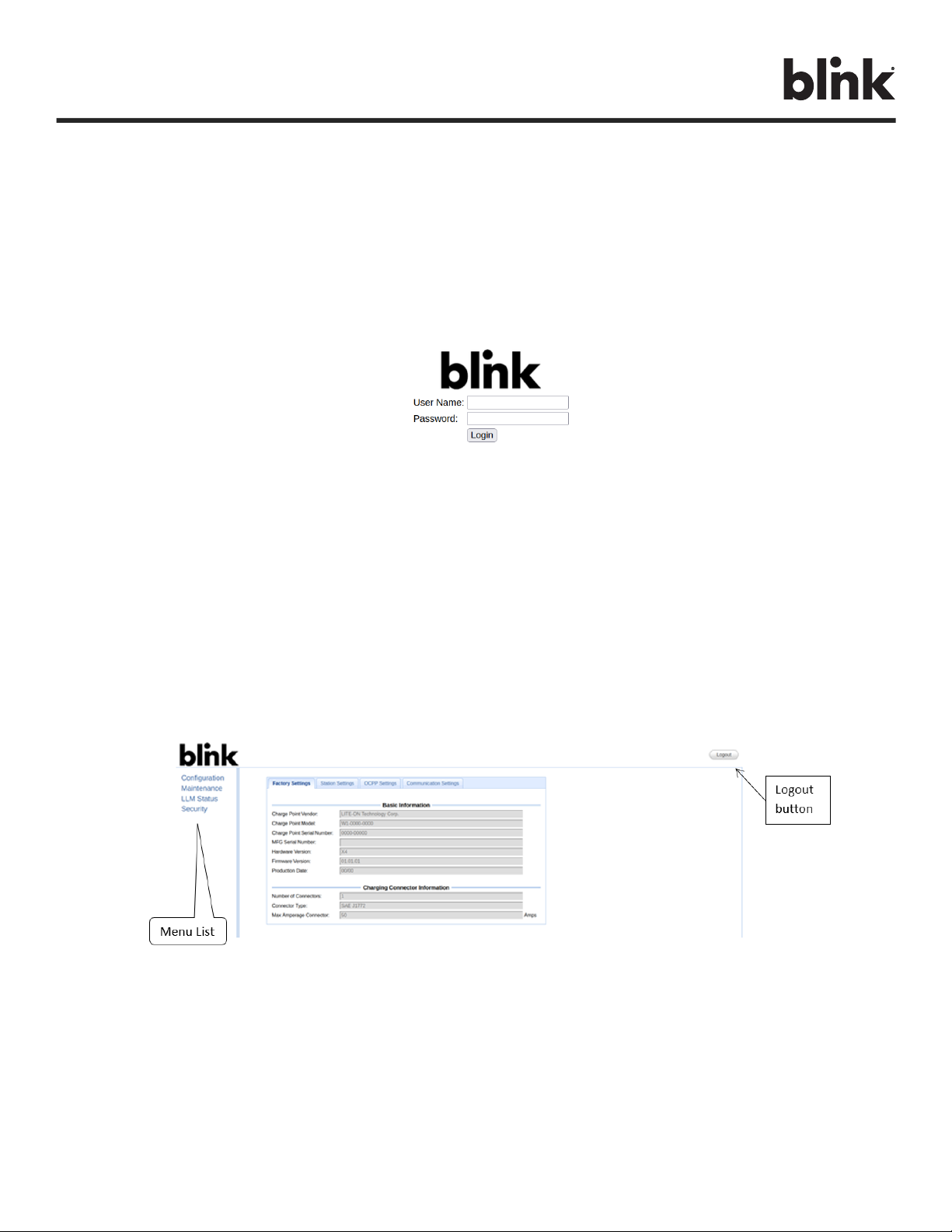
7.1.2. Login
Open a web browser (Internet Explorer for example) and enter the IP address (10.10.0.1) in the address
field of the browser and press enter.
The login screen appears as in Figure below:
Figure 7. Web Portal Screen
Enter “admin” in the user name box. The default password is “howru2RU2IC3”.
7.2. Web Page Overview
7.2.1. Menu Overview
To navigate via the web browser, use the menu items available: Configuration, Maintenance, EVSE
Status, LLM Status, and Security, shown in the figure below.
Figure 8. Menu Overview
Charge on.
BlinkCharging.com Page 18 of 56
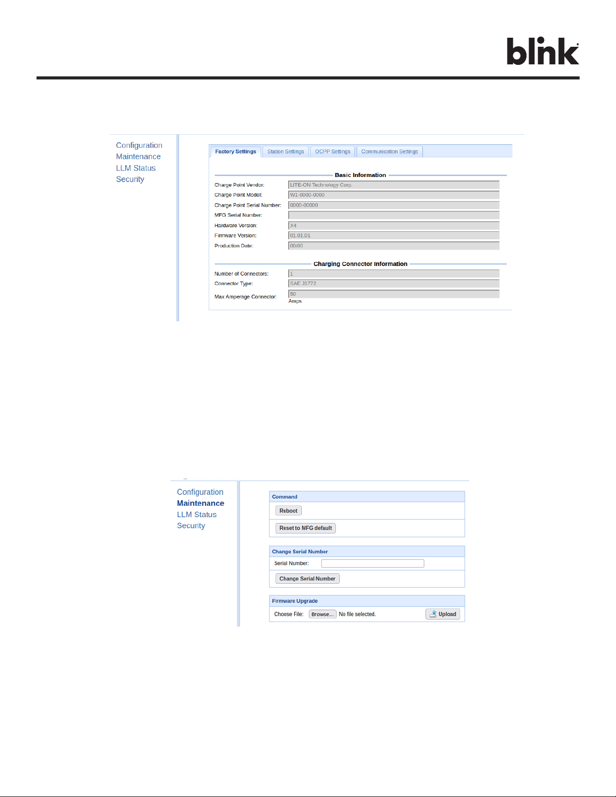
7.2.2. Configuration Menu
When you choose the Configuration menu, a sub menu will appear in the figure below.
Figure 9. Menu Overview - Configuration
• The “Factory Settings” tab is used to display the information of the EVSE.
• The “Station Settings” tab is used to set up the configuration regarding to the EVSE itself.
• The “OCPP Settings” tab is used to set up the custom properties for uses in OCPP 1.6 services.
• The “Communication Settings” tab is used to set up the network connection and load
management.
7.2.3. Maintenance Menu
When you choose the Maintenance menu, a sub menu will appear in the figure below.
Figure 10. Menu Overview - Maintenance
• The “Command” screen can be used to restart the EVSE and reset settings to Manufacturing
default.
• The “Change Serial Number” screen can change the serial number of the EVSE.
• The “Firmware Upgrade” screen can be used to upgrade the firmware of the EVSE.
Charge on.
BlinkCharging.com Page 19 of 56
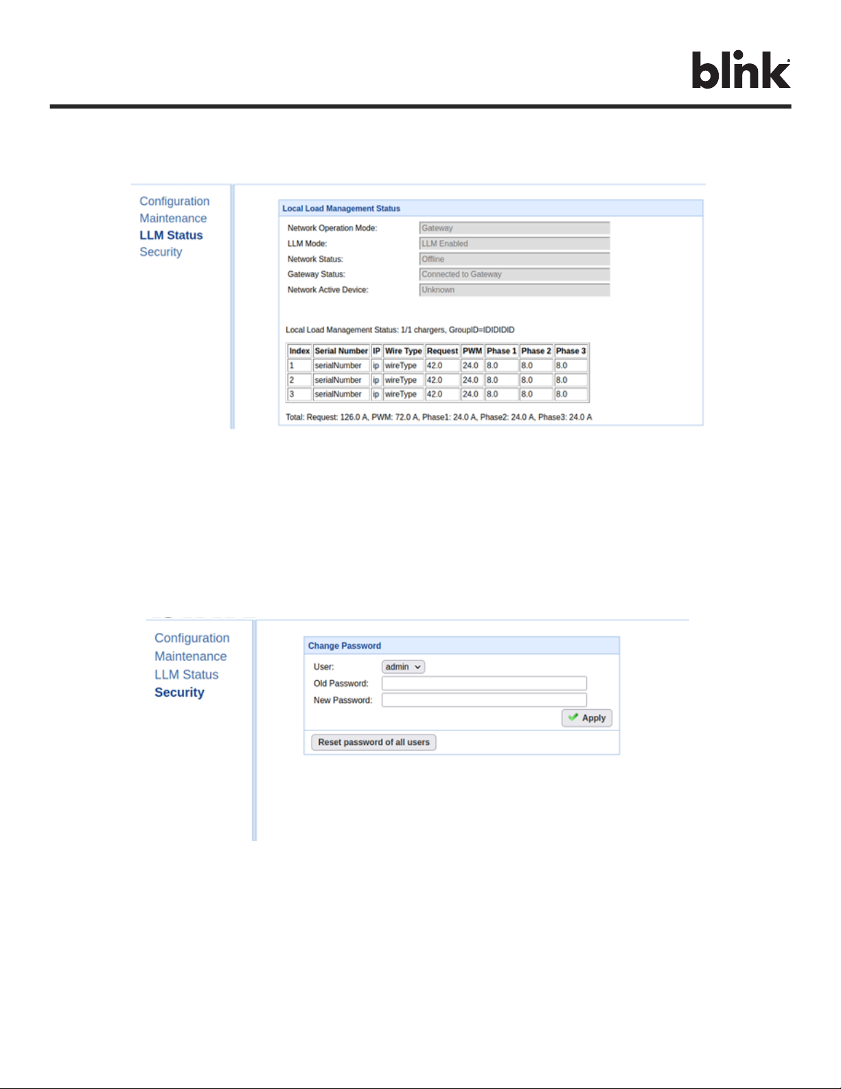
7.2.3.1. LLM Status Menu
When you choose the LLM Status menu, a sub menu will appear in the figure below.
Figure 11. Menu Overview - LLM Status
The “Local Load Management Status” screen shows the Local Load Management (LLM)
settings and current Master/Slave group member list.
7.2.4. Security Menu
When you choose the Security menu, a sub menu will appear in the figure below.
Figure 12. Menu Overview - Security
The “Change Password” screen can be used to change the password of users for this web
portal.

Charge on.
BlinkCharging.com Page 20 of 56
7.3. Configuration
7.3.1.1. Factory Settings
Clicking on the “Configuration” and then “Factory Settings” link will bring up the following
screen:
Figure 13. Menu Overview - Configuration
Basic Information
• EVSE Vendor – The vendor’s name of the EVSE.
• EVSE Model – The model’s name of the EVSE.
• EVSE Serial Number – The unique serial number of the EVSE.
• Firmware Version – The software version of the EVSE.
• Production Date – The production date of the EVSE.
Charging Connector Information
• Number of Connectors – Number of connectors of the EVSE.
• Connector Type – Indicates type 1 or type 2 cable installed in the EVSE.
• Max Amperage Connector – The maximum charging current of the connector capability.
Table of contents
Other B-Link Batteries Charger manuals

B-Link
B-Link 6 Series User manual

B-Link
B-Link DS Series Manual

B-Link
B-Link DC Fast Charger User manual

B-Link
B-Link WE-30C User manual

B-Link
B-Link Wall Mount Charging System User manual

B-Link
B-Link SEMACONNECT 7 Series User manual

B-Link
B-Link DS Series Manual

B-Link
B-Link HQ 200 User manual

B-Link
B-Link Basic Charger-32A User manual

B-Link
B-Link SemaConnect US Manual


