B-Link bluecorner PQ 150 User manual

www.bluecorner.be
PQ 150
USER MANUAL

Installation Manual
www.bluecorner.be 2
1. GENERAL
Read the instruction manual carefully before operating the unit.
The instruction manual will help you to
• use the product correctly
• detect damage early, and prevent or repair damage
• avoid failure and repair costs
• extend the product service life and increase reliability
• avoid environmental hazards
The instruction manual forms an essential part of the product and must be retained for later use.
Blue Corner will not be liable for damages resulting from not following the instructions in this manual.
2. SAFETY INSTRUCTIONS
Warning!
Not following the safety instructions could result in a risk to life or of injury, as well as damage to the unit. Blue
Corner disclaims all liability for claims resulting from not following the safety instructions.
Electrical Hazard! Fire Hazard!
Never use worn, damaged or dirty charge connectors, Connector Units or Smart Attachments!
The electrical system to which the charging unit is connected and on which it runs must be inspected by a
qualified electrician. The current circuit of the socket that will be used for charging must have its own residual
current protective unit and a circuit breaker. Only use properly installed, undamaged sockets and an electrical
system that is in perfect working order for charging.
On unknown sockets the vehicle charging current must be set to the lowest current value!
The owner (end customer) must make sure the charging unit is always in immaculate condition when in
operation!
The charging unit must be regularly inspected for damage to the housing, the charging connector, Connector
Unit and Smart Attachment (visual check)!
If the charging unit is damaged, it must be disconnected from the grid immediately. The damaged unit must not
be connected to the power grid again and must be replaced!

Installation Manual
www.bluecorner.be 3
Repairs may not be carried out on the charging unit. Repairs may only be carried out by the manufacturer
(replacement of the charging unit)!
Do not make any unauthorized modifications to the charging unit!
Contacts must not be oiled, greased or treated with contact spray!
Do not remove labels such as the rating plate, warning notices, current limit marks or display symbols!
Never disconnect the Connector System while charging is in progress! Before stopping the charging process, first
unplug the charging connector from the vehicle and then unplug the grid connector.
Always follow the correct sequence when connecting plugs!
Additional extension cables may not be used for connection to the power grid as well as to the vehicle!
The charging unit and all included accessories must only be used to charge the drive battery of electric or plug-
in-hybrid vehicles. The unit may not be used with different types of loads (improper use)!
Read the information and instructions for your vehicle carefully before you charge the vehicle using the charging
unit!
Before charging the vehicle, make sure that it is sufficiently secured against rolling away!
Do not run the charging unit in a thermally insulated or encapsulated vessel or container due to the risk of
overheating.
When using a Smart Attachment, never set a higher charging current than
1) the maximum current the Smart Attachment is approved for.
2) the maximum current the upstream installation and socket are approved for.
If the power supply socket feels hot when charging is in progress, replace this socket immediately!
Never use force to pull on the cable ends of the charging unit!
Never connect or disconnect plug connections between grid connector, Smart Attachment, Connector Unit or
vehicle inlet while the PQ 150 is in charging mode!
The use as a rope for lifting or pulling mechanical loads or for wrapping or tying up objects is strictly prohibited!
The charging unit may only be operated in accordance with its intended use!

Installation Manual
www.bluecorner.be 4
When removing the cable from the socket pull on the Connector System, never the cable!
Protect the charging unit and the charging cable from mechanical damage (running over, pinching or kinking)
and the electrical contact area from heat sources, dirt and water!
Note that the Smart Attachments must be fitted with the IP 24 protective cover supplied when not connected in
order to provide a sufficient IP protection level.
Only use Smart Attachments and accessories supplied by Blue Corner with the charging unit or those that are
approved by Blue Corner.
The Smart Attachments contain a Neodymium magnet which may not be brought into direct body contact with
heart pacemakers out of safety reasons.
PQ 150 contains telecommunication hardware which may not be brought into direct body contact with heart
pacemakers out of safety reasons.
In the following countries the charging current may not be set higher than 10A if a Schuko adapter plug is used:
Norway
In the following countries the charging current may not be set higher than 8A if a Schuko adapter plug is used:
Finland, France and Switzerland
In the following countries the charging current may not be set higher than 6A if a Schuko adapter plug is used:
Denmark
If a Schuko Smart Attachment is used, the weight of the charging unit must not put strain on the socket. Relieve
the strain on the cable (e.g. by placing the unit on something or hanging the cable over a hook).
During a single phase charging operation within a 3-phase-grid, the requirements of the grid operator for
asymmetric grid loads needs to be considered. The charging power may not be set to a higher value than the
maximum single phase power drain permitted by the grid operator.
3. INTENDED USE
The charging and all included accessories unit may only be used to charge the drive battery of an electric or
plug-in-hybrid vehicle. Section 5 ”Product Description” describes operation of the charging unit.
Any other use will be considered as improper use. Blue Corner does not assume liability for any damage that
results from such improper use!
Intended use includes following the instructions in this manual as well as observance of all labeling such as type
plates,warning notices, current limit marks, display symbols and ambient conditions.

Installation Manual
www.bluecorner.be 5
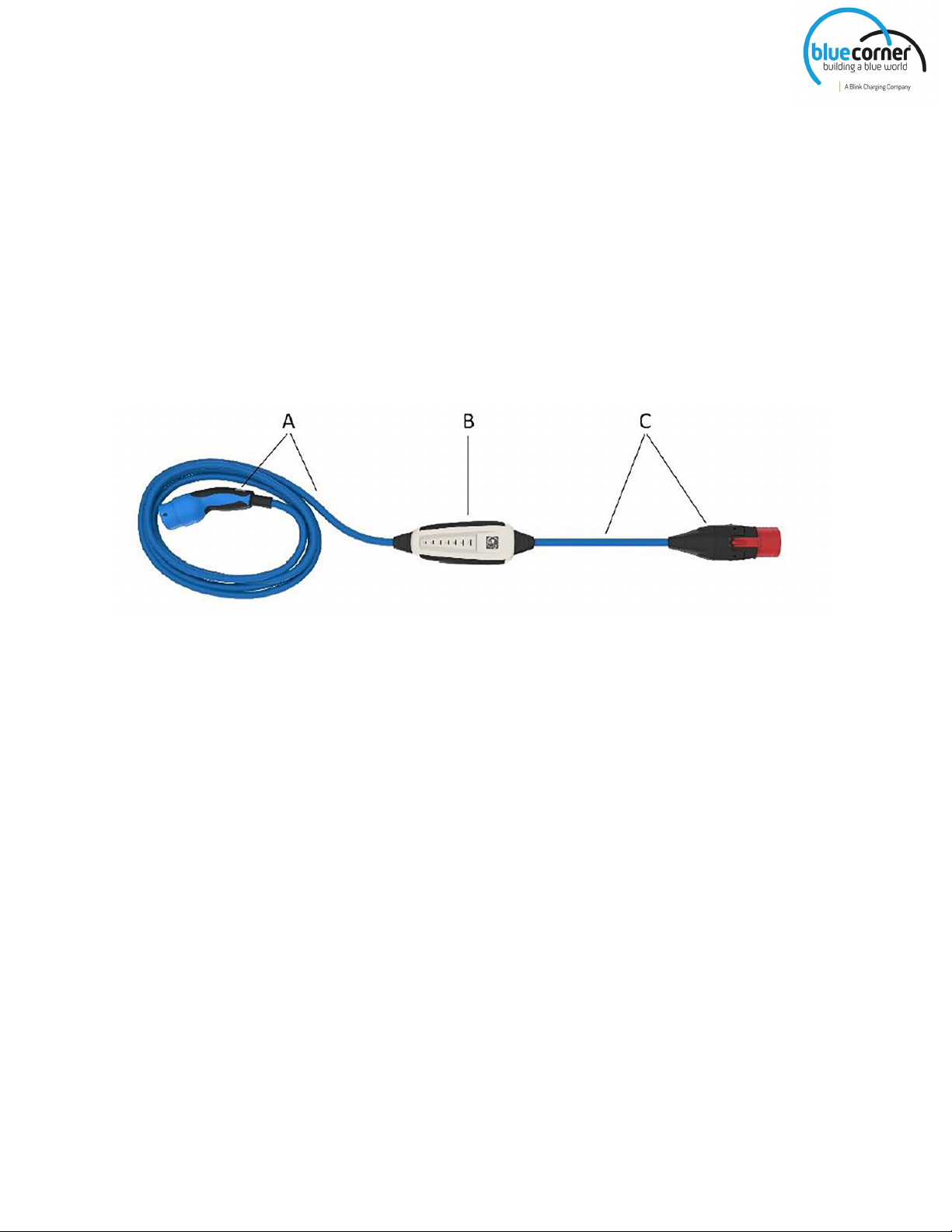
4. PRODUCT DESCRIPTION
The standard version of the PQ 150 charging unit consists of:
A. the charging cable with the vehicle connector
B. the electronics in a plastic housing (IC-CPD) including the residual current protection mechanism and energy
meter with GSM and GNSS interface (GSM: EDGE, GPRS, 4G
M1, 4G NB-IoT; GNSS: GPS, GLONASS, Galileo, Baidou)
C. the power grid cable with the patented high level safety Connector System, consisting of the Connector Unit
and one or more Smart Attachments used to connect it to the power grid (in picture: CEE 32A)
Product features:
• Total cable length: 7.5m
• Vehicle connector acc. to IEC 62196 (Type 2)
• 3-phase
• Maximum charging current 32A
• With GSM and GNSS interface (GSM: EDGE, GPRS, 4G M1, 4G NB-IoT; GNSS: GPS, GLONASS,
Galileo, Baidou) connected to the Blue Corner backoffice.
The integrated residual current protection mechanism means PQ 150 charges your vehicle in accordance with
the highest safety standards. The mechanism breaks the current reliably if AC or DC residual currents occur.
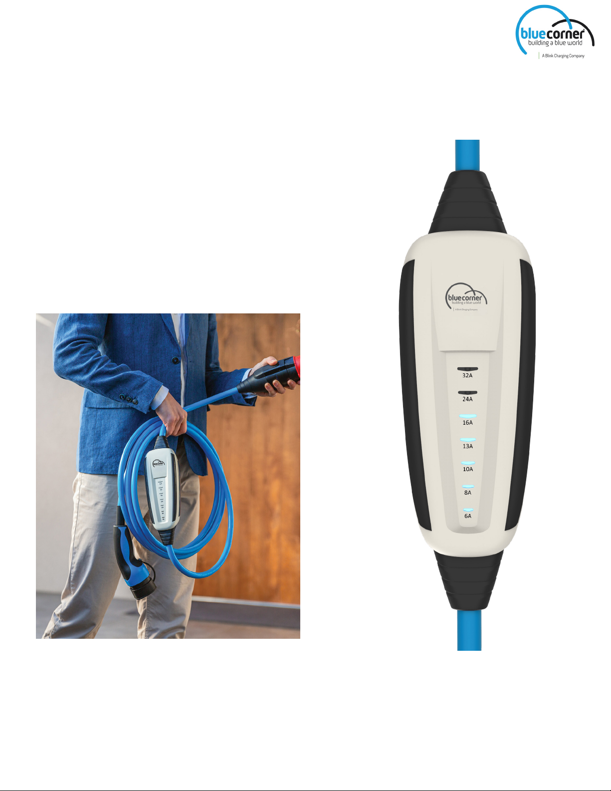
The charging unit is designed such that it is easy to adjust the charging current via a touch sensitive field on the
device.
The LED indicator shows you the selected charging current at all times. The energy meter provides additional
functions with full transparency and visibility into every charging event.

Installation Manual
www.bluecorner.be 6
5.1 CHARGING UNIT – PQ 150
1) Touch sensitive field
2) Display: Selectable maximum charging current
3) LED indicator: Selected charging current
5.2 PATENTED HIGH LEVEL SAFETY CONNECTOR SYSTEM WITH
TEMPERATURE MONITORING AND HOT-UNPLUG PROTECTION
Note: There are many different Smart Attachments available for all standard sockets and Type 2 connections.
In the example above the Smart Attachment CEE 32A (standard in package) is shown.

Installation Manual
www.bluecorner.be 7
5.3 CHARGING YOUR ELECTRIC VEHICLE AT STANDARD POWER
SUPPLY SOCKETS
First, push the Smart Attachment onto the Connector Unit until you hear and feel it click into place. Then connect
the Connector System to the power supply socket. The charging electronics will then initialize which is shown
by an oscillating flashing signal of the LEDs. At the same time an automatic self check which tests all essential
functions is carried out. Furthermore, this self check will be carried out at every charging request. In case the self
check fails, possible errors areindicated via the LEDs. After a successful self check only the LED for the current that
was set the last time is illuminated.
Now select the charging current you want using the touch sensitive field. As long as the vehicle is not also
connected, you have unlimited time for this.
CAUTION! When choosing the charging current take all the following points into account:
a) Maximum current according to the supply cable of the electric system
b) Maximum current according to the grid connector used
c) If a Smart Attachment < 32A is used: Maximum charging current is automatically limited to the maximum
current the Smart Attachment is approved for. Before charging check the charging current which may have been
limited by the Smart Attachment.
Points a) and b) also apply when using any Smart Attachment.
Connect the vehicle connector to the vehicle. From this point on, the charging current can only be changed
for 20 seconds via the touch sensitive field of the unit due to the integrated protection against manipulation by
passers-by. Once this time has elapsed, all LEDs up to and including those of the set current are now lit. When
the vehicle is recognized by the charging unit, all LEDs light up shortly. If the vehicle is ready for charging, the
LED of the set charging current then moves up and down once (32A and 6A) and then back to the set charging
current and the charging process starts after a few seconds, depending
on the vehicle.
Note: If the correct connection sequence is not applied and the vehicle is already connected, you have around
20 seconds to set the charging current after connecting the charging unit to the power supply. After that all
LEDs will be illuminated up to and including those of the set current. From this point onwards it will no longer
be possible to change the charging current using the touch sensitive field on the unit. Alternatively, you can stop
charging and then disconnect the unit from the vehicle to adjust the charging
current via the touch sensitive field.
The set values for the charging current/charging power take the form of upper limits. Depending, for example,
on the battery charging status or the outside temperature, the vehicle may, over the course of the charging
process, set the actual charging current to a lower value than the current set directly on the PQ 150.
Note: PQ 150 may remain connected to the power socket when the vehicle is disconnected.
Connector System

Installation Manual
www.bluecorner.be 8
5.4 INTERRUPTING THE CHARGING PROCESS
The charging process should normally be stopped on the vehicle. Follow the instruction manual for your vehicle.
The vehicle connector will then be unlocked and can be unplugged. Finally, disconnect the Connector System of
the charging unit from the power socket.
Note: When disconnecting from the power supply, please always pull on the Connector System, not on the cable
of the charging unit.
Note: PQ 150 features the innovative safety measure “Hot unplug protection”. This means that disconnection
under load is not possible. Therefore, if the connection to the power socket is accidentally disconnected during
charging, PQ 150 ensures that the energy supply is interrupted before dangerous and damaging arcs can form.
5.5 CONNECTION SEQUENCE
STARTING THE CHARGING PROCESS STOPPING THE CHARGING PROCESS
1. Plug the Smart Attachement onto the Connector
unit.
1.Unlock the vehicle connector on the vehicle and
unplug it.
2. Insert the Connector system to the power supply. 2. Disconnect the Connector System from the grid.
3. Connect the vehicle connector to the vehicle. 3. PQ 150 can, however, also remain connected to
the power socket permanently.
5.6 THEFT-PROTECTED AND TAMPER-PROOF
Electric vehicles with type 2 charging socket lock the vehicle connector after it is plugged in. This means your PQ
150 is protected against theft during and after charging. The socket can only be unlocked via the vehicle. For
details on the behavior of your electric vehicle, please refer to the operating manual of your car.
PQ 150 has a protection system to prevent the charging current settings being tampered with by passers-by:
• The charging current can only be adjusted via the touch sensitive field after connection to the power supply. If
the vehicle connector is already plugged in, you have max. 20 seconds left to adjust the settings (see 5.3).
• It is no longer possible to change the charging current via the touch sensitive field – even if the PQ 150’s
power supply is disconnected and the device re-initialises after being plugged in again. Setting the charging
current is only possible again when the Type 2 charging socket is unlocked via the vehicle and PQ 150 is
disconnected from the electric car.

Installation Manual
www.bluecorner.be 9
5.7 ERROR MODE
Errors are indicated by flashing LEDs on the PQ 150 and the Connector Unit and through acoustic signals. The
following signals are possible on PQ 150:
• 5x flashing of all LEDs + short break (repeating)
Indicates a general fault. Please disconnect the PQ 150 from the electric vehicle and the power socket. Now
connect the PQ 150 to the power socket again. If the fault still occurs, please contact your dealer.
The “Error” mode can only be reset by disconnecting the power supply. In case of an error, check for a vehicle-
related fault or a fault in the plug connections.
• LED 32A is permanently illuminated, all other LEDs are flashing
Indicates an irregularity of the residual current protection mechanism. A too high residual current created by the
electric vehicle has triggered the residual current protection mechanism of the PQ 150. This is caused by an error
of the vehicle or by a defect of the cable from the electric vehicle leading to the PQ 150
Disconnect the PQ 150 from the vehicle and the grid and check, possibly with the involvement of a skilled
electrician or a workshop, if one of the causes described above has occurred. Then reconnect the PQ 150 to the
grid. If the error persists please contact your dealer.
• Flashing of the 6A LED and the LED of the selected charging current (repeating)
Indicates an irregularity of the PE conductor test. Make sure that the electrical installation and the protective
conductor are connected correctly.
This error can be acknowledged by pressing the letters “32A” on the touch sensitive field for at least three
seconds.
Note: In some countries, e. g. Norway, ground-free power grids are prevalent. Charging in these grids
is possible via acknowledgement of the error as described before. After acknowledgement this is shown
permanently during the charging process with the flashing green 6A LED.
• LED 24A is permanently illuminated, all other LEDs are flashing
Indicates an irregularity on the check of the internal switching contact. Disconnect the PQ 150 from the vehicle
and the grid. Then reconnect the PQ 150 to the grid. If the error persists please contact your dealer.
• LED 16A is permanently illuminated, all other LEDs are flashing
Indicates that the charging process had to be terminated for safety reasons due to excessive heat generated by
the power socket. Please disconnect the PQ 150 from the electric vehicle and the power supply and check, if
necessary with the help of a qualified electrician, whether the power supply and socket are properly installed
and free of defects. In the meantime, use a different socket, ideally on a different power supply. If the error
continues to occur, please contact your dealer.

Installation Manual
www.bluecorner.be 10
• LED 6A, 8A, 10A, 13A are illuminated permanently, all other LEDs are flashing
Indicates an error detected by the overvoltage protection. One possible cause of an overvoltage is an incorrectly
installed socket. Disconnect the charging unit from the power supply and check, with the help of an electrician if
necessary, that the power supply line and socket are properly installed and free of faults. In the meantime, use a
different socket, ideally on a different power supply line. If the error persists, please contact your dealer.
• LED 13A, 16A, 24A, 32A are illuminated permanently, all other LEDs are flashing
Indicates an error detected by the undervoltage protection. In general, PQ 150’s integrated autonomous load
management enables it to regulate the charging current independently if the voltage is too low due to an
overload on the power grid, thereby stabilising the grid. If this error is still displayed, check whether your power
grid is overloaded and there is insufficient mains voltage, if necessary with the help of a qualified electrician.
• One LED flashes alternately at random
Indicates an error detected by the hot-unplug detection and means that the connection between the Connector
Unit and the Smart Attachment or between the Smart Attachment and the socket has not been fully established.
Disconnect the charging unit including the Smart Attachment from the socket and make sure that the Smart
Attachment is fully engaged in the Connector Unit. Then re-establish the connection to the socket and make sure
that the Smart Attachment is fully inserted into the socket.
• No LED is illuminated
Make sure that the electrical installation is connected correctly. PQ 150 requires mains voltage between phase 1
and neutralto supply the electronics.
5.8 INTEGRATED FUNCTIONS
• Charging electronics in conformity with EN 62752 (control pilot circuit according to IEC/TS 62763)
• Residual current protection for direct as well as for alternating residual current (continual surveillance in the
“vehicle charging” mode).
• Energy meter for voltage, current, power and energy measurement
• GSM and GNSS interface (GSM: EDGE, GPRS, 4G M1, 4G NB-IoT; GNSS: GPS, GLONASS,
Galileo, Baidou) for data exchange with the Blue Corner backoffice.

Installation Manual
www.bluecorner.be 11
6. SMART ATTACHMENTS
Only use Smart Attachments and accessories supplied with the charging unit or those approved by Blue Corner
Take note of the maximum current that can be set for the specific Smart Attachment!
In addition, PQ 150 features an automatic detection of the Smart Attachments. This ensures that the maximum
permitted charging current for which the Smart Attachment has been approved for cannot be exceeded.
7. MAINTENANCE
The charging unit is maintenance-free. Regularly check the housing of the charging unit, the charging cables
and the connectors by a visual check for external damage. If damage is found, the charging unit may under no
circumstances be used.
8. CLEANING
If required, clean the charging unit with a damp cloth. Avoid cleaning agents with solvents.
9. REGISTRATION/PERMISSION BY THE NETWORK OPERATOR
Please note that your network operator may require you to register and/or acquire a permission for your
charging equipment for electric vehicles and comply with the respective regulations of the network operator. For
example the essential requirements for Germany are consolidated in the VDE-AR-N 4100:2019-04.

Installation Manual
www.bluecorner.be 12
10. TECHNICAL DATA
Product name PQ 150
Nominal voltage 230V/400V 50Hz
Nominal current 32A
Maximum charging power 22kW
Residual current protection (AC) 30mA
Residual current protection (DC) 6mA
IP protection class IP67
Charge mode Mode 2 acc. to EN 62752
Mode 3 when using Smart Attachment Type 2
Ambient conditions -40°C … +70°C (Standard: +45 °C)
5% - 95% humidity
max. 4000m altitude
Weight 5m model approx. 4,1 kg
Housing dimensions (L, W, H) 216mm x 90mm x 64mm
Telecommunication technologies GSM and GNSS interface (GSM: EDGE, GPRS, 4G M1,
4G NB-IoT; GNSS: GPS, GLONASS, Galileo, Baidou) to the Blue
Corner Backoffice.

Installation Manual
www.bluecorner.be 13
11. DISPOSAL
The packaging and the unit must be disposed of according to applicable local and regional regulations in the
place where the unit is operated.
Run-down or faulty batteries must be disposed of separately in accordance with national and local regulations on
environmental protection and recycling.
This product may not be treated as ordinary waste and must be returned to a collection point for the recycling
of electronic equipment. For more information, contact your local authority, a local waste disposal service or the
company from which you purchased the product.
12. DECLARATION OF CONFORMITY
PQ150
(Charging unit for electric vehicles)
Blue Corner / Blink Charging
Posthoflei 3 bus 4
2600 Berchem
Belgium
+32 3 337 38 30
info@bluecorner.be
The item described complies with the following relevant directives and standards:
Directive 2014/35/EU electrical equipment (Low voltage directive)
Directive 2014/30/EU electromagnetic compatibility (EMC)
Directive 2014/53/EU radio equipment (RED)
Directive 2011/65/EU hazardous substances in electrical and electronic equipment (ROHS)
IEC/EN 62752 In-cable control and protection device for mode 2 charging of electric road vehicles
IEC/EN 62196-1 Plugs, socket-outlets, vehicle connectors and vehicle inlets - Conductive charging of
electric vehicles
IEC/EN 60309-2 Plugs, socket-outlets and couplers for industrial purposes
ETSI EN 301 489-1 V2.1.1 Electromagnetic Compatibility (EMC) standard for radio equipment and services;
Part 1:
Common technical requirements; (2017-02)
ETSI EN 301 489-17 V3.1.1 Electromagnetic Compatibility (EMC) standard for radio equipment and services;
Part
Specific conditions for Broadband Data Transmission Systems; (2017-02)

Installation Manual
www.bluecorner.be 14
EN 55014-1 Electromagnetic compatibility - Requirements for household Appliances, electric tools
and similar Apparatus (April 2017) - Part 1: Emission (CISPR 14-1:2016 + COR1:2016)
EN 55014-2 Electromagnetic compatibility - Requirements for household Appliances, electric tools
and similar Apparatus (April 2015) - Part 2: Immunity - Product family standard (CISPR
14-2:2015)
EN 61000-3-2 Electromagnetic compatibility (EMC) - Part 3-2: Limits - Limits for harmonic current
emission (IEC 61000-3-2:08/2014)
EN 61000-3-3 Electromagnetic compatibility (EMC) – Part 3-3: Limits – Limitation of voltage changes,
voltage fluctuations and flicker in public low-voltage supply systems. (IEC 61000-3-
3:08/2013)
EN 61000-6-2 Electromagnetic compatibility (EMC) – Part 6-2: Generic standards – Immunity for
industrial environments (IEC 61000-6-2:08/2005)
Table of contents
Other B-Link Batteries Charger manuals

B-Link
B-Link TP-EVPD-30kW User manual

B-Link
B-Link WE-30C User manual

B-Link
B-Link DC Fast Charger User manual

B-Link
B-Link IQ 200 User manual

B-Link
B-Link HQ 200 User manual

B-Link
B-Link Basic Charger-32A User manual

B-Link
B-Link Wall Mount Charging System User manual

B-Link
B-Link 6 Series User manual

B-Link
B-Link SemaConnect US Manual

B-Link
B-Link DS Series Manual