B-Link Basic Charger-32A User manual
Installation Manual
Basic/Smart/Intelligent Charger-32A Revision 4.0
www.tritium.com.au
Veel®isaregisteredtrademarkofTritiumPtyLtd.©2018TritiumPtyLtd
BlinkCharging.com • (888) 998.2546
©2019 Blink Charging Co. • NASDAQ: BLNK
BlinkCharging.com • (888) 998.2546
©2021 Blink Charging Co. • NASDAQ: BLNK
Basic/Smart/Intelligent Charger-32A Installation Manual Rev. 4.0
BlinkCharging.com • (888) 998.2546
©2021 Blink Charging Co. • NASDAQ: BLNK
I
IMPORTANT SAFETY INSTRUCTIONS
This document contains instructions and warnings that must be followed when installing and
using the Electric Vehicle Supply Equipment (EVSE). Before installing or using the EVSE, read this
entire document as well as WARNING and CAUTION markings in this document.
Safety Instructions
The symbols used have the following meaning:
The charge point must be installed only by licensed electricians.
Make sure that the materials used and the installation procedures follow local building
codes and safety standards.
The information provided in this manual in no way exempts the user of responsibility to
follow all applicable codes or safety standards.
This document provides instructions for the charge point and should not be used for any
other product. Before installation or use of this product, review this manual carefully and
consult with a licensed contractor, licensed electrician, or trained installation expert to make
sure of compliance with local building codes and safety standards.
WARNING: RISK OF PERSONAL INJURY
WARNING: RISK OF ELECTRIC SHOCK
WARNING: RISK OF FIRE
CAUTION: RISK OF DAMAGE TO THE EQUIPMENT

Repair and Maintenance Clause
Only licensed electricians can repair or maintain the charge point. It is forbidden for general
users to repair or maintain it.
Turn off input power before repair or maintenance the charge point.
Federal Communication Commission Interference Statement
This device complies with Part 15 of the FCC Rules. Operation is subject to the following two
conditions: (1) This device may not cause harmful interference, and (2) this device must accept
any interference received, including interference that may cause undesired operation.
This equipment has been tested and found to comply with the limits for a Class B digital device,
pursuant to Part 15 of the FCC Rules. These limits are designed to provide reasonable protection
against harmful interference in a residential installation. This equipment generates, uses and
can radiate radio frequency energy and, if not installed and used in accordance with the
instructions, may cause harmful interference to radio communications. However, there is no
guarantee that interference will not occur in a particular installation. If this equipment does
cause harmful interference to radio or television reception, which can be determined by turning
the equipment off and on, the user is encouraged to try to correct the interference by one of
the following measures:
- Reorient or relocate the receiving antenna.
- Increase the separation between the equipment and receiver.
- Connect the equipment into an outlet on a circuit different from that to which the receiver is
connected.
- Consult the dealer or an experienced radio/TV technician for help.
FCC Caution: Any changes or modifications not expressly approved by the party responsible for
compliance could void the user's authority to operate this equipment.
This transmitter must not be co-located or operating in conjunction with any other antenna or
transmitter.
Radiation Exposure Statement:
This equipment complies with FCC radiation exposure limits set forth for an uncontrolled
environment. This equipment should be installed and operated with greater than 20cm
between the radiator & your body.
Basic/Smart/Intelligent Charger-32A Installation Manual Rev. 4.0
BlinkCharging.com • (888) 998.2546
©2021 Blink Charging Co. • NASDAQ: BLNK
II

Industry Canada statement:
This device complies with ISED’s license-exempt RSSs. Operation is subject to the following two
conditions: (1) This device may not cause harmful interference, and (2) this device must accept
any interference received, including interference that may cause undesired operation.
Le présent appareil est conforme aux CNR d’ ISED applicables aux appareils radio exempts de
licence. L’exploitation est autorisée aux deux conditions suivantes : (1) le dispositif ne doit pas
produire de brouillage préjudiciable, et (2) ce dispositif doit accepter tout brouillage reçu, y
compris un brouillage susceptible de provoquer un fonctionnement indésirable.
Radiation Exposure Statement:
This equipment complies with ISED radiation exposure limits set forth for an uncontrolled
environment. This equipment should be installed and operated with greater than 20cm
between the radiator & your body.
Déclaration d'exposition aux radiations:
Cet équipement est conforme aux limites d'exposition aux rayonnements ISED établies pour un
environnement non contrôlé. Cet équipement doit être installé et utilisé à plus de 20 cm entre
le radiateur et votre corps.
WARNING: RISK OF ELECTRIC SHOCK
Basic precautions should always be followed when using electrical products,
including the following:
• Read all the instructions before using this product.
• This device should be supervised when used around children.
• Do not put fingers into the EV connector.
• Do not uses this product if the flexible power cord or EV cable is frayed, has
broken insulation, or any other signs of damage.
• Do not use this product if the enclosure or the EV connector is broken,
cracked, open, or shows any other indication of damage.
• To avoid a risk of fire or electric shock, do not use this unit with an extension
cord.
WARNING: RISK OF ELECTRIC SHOCK
Improper connection of the equipment grounding conductor can result in a risk of
electric shock. Check with a qualified electrician or serviceman if you are in doubt
as to whether the product is properly grounded.
Do not modify the plug provided with the product – if it will not fit the outlet, have a
proper outlet installed by a qualified electrician.
Basic/Smart/Intelligent Charger-32A Installation Manual Rev. 4.0
BlinkCharging.com • (888) 998.2546
©2021 Blink Charging Co. • NASDAQ: BLNK
III
SAVE THESE INSTRUCTIONS
WARNING: RISK OF ELECTRIC SHOCK
Do not remove the cover or attempt to open the enclosure. No user serviceable parts inside. Refer servicing to
qualified service personnel.
WARNING: RISK OF ELECTRIC SHOCK
• Do not touch live electrical parts.
• Incorrect connections may cause electric shock.
• Do not Disconnect Under Load.
WARNING: This equipment is intended only for charging vehicles that do not
require ventilation during charging. Please refer to your vehicle’s owner’s manual
to determine ventilation requirements.
WARNING: Do not use extender cables to increase the length of the charging cable.
Maximum length is limited to 25 feet by the National Fire Protection Agency.
WARNING: Do not drag the charge point by input power cord.
CAUTION: Do not expose to liquid, vapor or rain.
CAUTION: If this unit is installed outdoors, the outlet must be rated for outdoor
installation. The outlet must be installed properly to maintain the proper NEMA
rating of the enclosure.
• Installation work and electrical wiring must be done by qualified person(s) in
accordance with all applicable codes and standards, including fire-rated
construction.
• Do not touch the terminals or other current-carrying parts.
• Take care not to drill into any pipes or power lines beneath the surface during
mounting holes preparation. Use power line / metal detector.
• Do not trample or drive over the product’s cables.
• Do not put any foreign objects into the enclosure.
• Do not start the engine when the charging connector is still connected.
CAUTION: Do not use this product if there is any damage to the unit. Send the unit
back to the manufacturer in the event the unit is not operational.
Basic/Smart/Intelligent Charger-32A Installation Manual Rev. 4.0
BlinkCharging.com • (888) 998.2546
©2021 Blink Charging Co. • NASDAQ: BLNK
IV

1
Contents
1
Introduction ............................................................................................................................. 2
Product View ............................................................................................................... 2
2
Installation................................................................................................................................ 4
Before Installation ....................................................................................................... 4
Tools & Parts Required for Installation ........................................................................ 5
SIM Card Installation (for IC3 only) .............................................................................. 5
Install the Charge Point ................................................................................................ 7
Input cord connection (for IC3 only) .......................................................................... 11
Install the Holster....................................................................................................... 15
Basic/Smart/Intelligent Charger-32A Installation Manual Rev. 4.0
BlinkCharging.com • (888) 998.2546
©2021 Blink Charging Co. • NASDAQ: BLNK
1 Introduction
This user manual applies to “32A Level 2 AC Charger for Plug-in Electric Vehicles (PEVs) and
Battery Electric Vehicles (BEVs)”.
The Level 2 Electric Vehicle Supply Equipment (EVSE) with 32A capabilities will be used in North
America. It can provide a shorter charging time than the traditional 16A EVSE.
!!! Any unauthorized modifications will void the manufacturer’s warranty. !!!
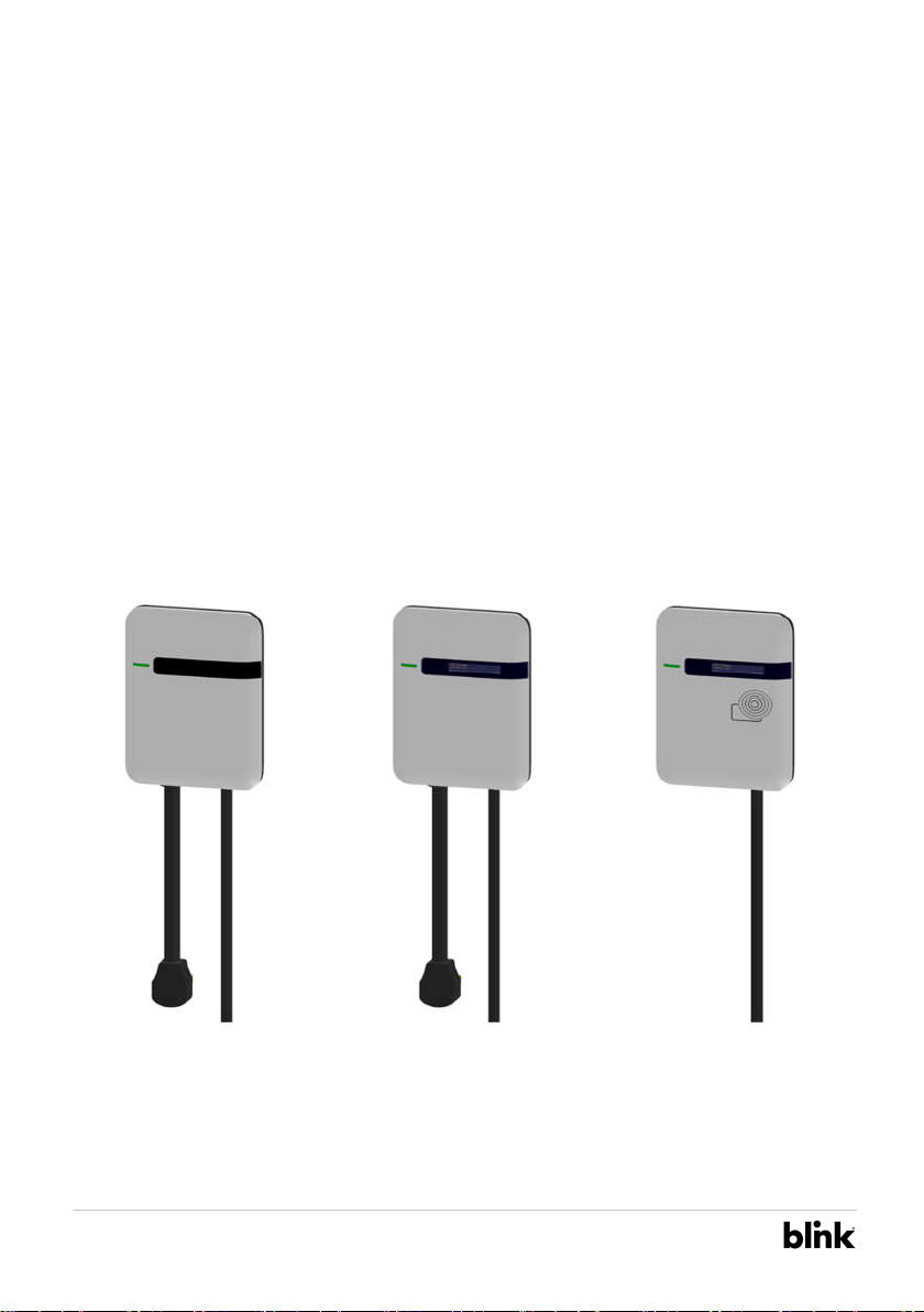
1.1 Product View
Different models of Charger:
Basic Charger-32A (BC3) Smart Charger-32A (SC3) Intelligent Charger-32A (IC3)
Figure 1-1 Front view
2
Basic/Smart/Intelligent Charger-32A Installation Manual Rev. 4.0
BlinkCharging.com • (888) 998.2546
©2021 Blink Charging Co. • NASDAQ: BLNK
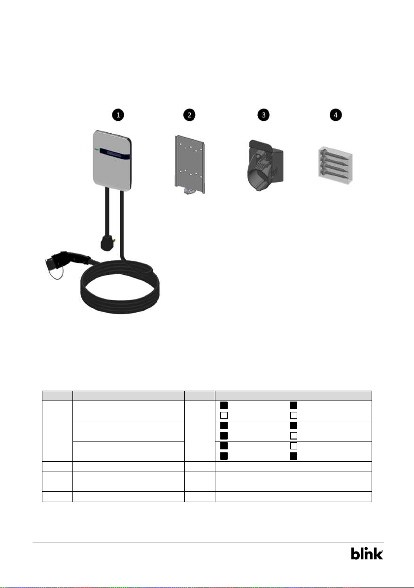
Box Contents
See the table below for differences in the box content of three models.
Figure 1-2 Box contents
Table 1-1 Accessories in the box
Item
Description
QTY
Remark
1
Basic Charger-32A (BC3)
1
Charging Plug
Input Power Cord
OLED Display
RFID Icon
Smart Charger-32A (SC3)
Charging Plug
Input Power Cord
OLED Display
RFID Icon
Intelligent Charger-32A (IC3)
Charging Plug
Input Power Cord
OLED Display
RFID Icon
2
Mounting Bracket
1
Attached to the back of the charge point
3 Holster ASSY 1
With Hook x1, Holster x1 & M4xL15 tapping
screw x2
4
Screw Bag
1
With #12xL50 tapping screw x4
3
Basic/Smart/Intelligent Charger-32A Installation Manual Rev. 4.0
BlinkCharging.com • (888) 998.2546
©2021 Blink Charging Co. • NASDAQ: BLNK
2 Installation
2.1 Before Installation
2.1.1 Safety check
• Check for transport damages.
• Before connecting the product to the power supply, check that the power supply voltage
and current rating corresponds with the power supply details shown on the product
rating label.
The charge point must be installed only by a licensed electrician in accordance with the provisions
of the local electrical industry construction and should comply with national electrical codes and
standards.
Before installing the charge point, make sure you have read all of these instructions in this manual
and fully understand its contents.
Appropriate protection is required when connecting to a main switchboard. The tools and
parts used as outlined in the section “Tools & parts required for installation”.
2.1.2 Grounding Instructions
The charge point must be implemented equipment grounding through a permanent wiring
system or an equipment grounding conductor. Use a wire with a dedicated grounding wire and a
ring terminal and connected to the equipment ground terminal block for grounding.
CAUTION: Disconnect the power supply before installing or repairing the charge
point. Failure to do so may result in physical injury or damage to the power supply
system and the charge point.
CAUTION: Avoid touching or pressing the OLED screen all times, as this may result in
damage to the OLED screen.
DANGER: RISK OF SUFFOCATION
Keep any packing materials away from children – these materials are a potential
source of danger, e.g. suffocation.
4
Basic/Smart/Intelligent Charger-32A Installation Manual Rev. 4.0
BlinkCharging.com • (888) 998.2546
©2021 Blink Charging Co. • NASDAQ: BLNK
2.2 Tools & Parts Required for Installation
Table 2-1 Tools & parts required for installation
Tool QTY Model
Size Supplier Remark
Mounting Bracket 1 All 194x109x9 mm Model Accessories Secure the charge point
Holster ASSY 1 All 58x58x70 mm Model Accessories Hold EV charging plug
Screw 4 All Tapping: #12 Model Accessories Secure Mounting Bracket &
Hook
Mechanical: M6 Commercially Available
Wire, Copper 3 IC3 8 AWG Commercially Available UL1015 (recommended)
Heat Shrink Tube 3 IC3 For 8 AWG wire Commercially Available
Terminal 3 IC3 For 8 AWG wire Commercially Available Connect input wires to the
terminal block
Conduit 1 IC3 1 inch Commercially Available
Torx Screwdriver 1 All T20 Commercially Available
Philips Screwdriver
1 All PH3 Commercially Available
Hexagon Socket 1 All 5/16 Commercially Available Tighten #12 Tapping screws
Torque Wrench 1 All 35 kgf-cm min Commercially Available
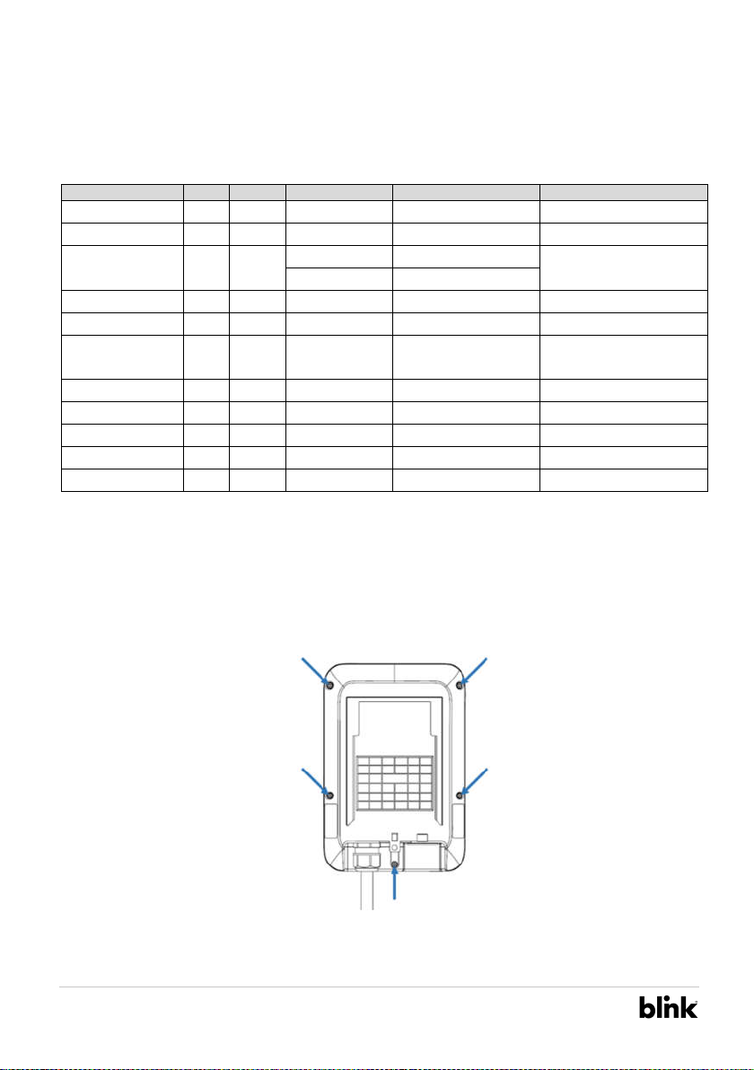
2.3 SIM Card Installation (for IC3 only)
1. Disassemble top cover
1-1 Loosen the screws (x5) on the base cover.
Figure 2-1 Position of five screws on Base Cover
5
Basic/Smart/Intelligent Charger-32A Installation Manual Rev. 4.0
BlinkCharging.com • (888) 998.2546
©2021 Blink Charging Co. • NASDAQ: BLNK
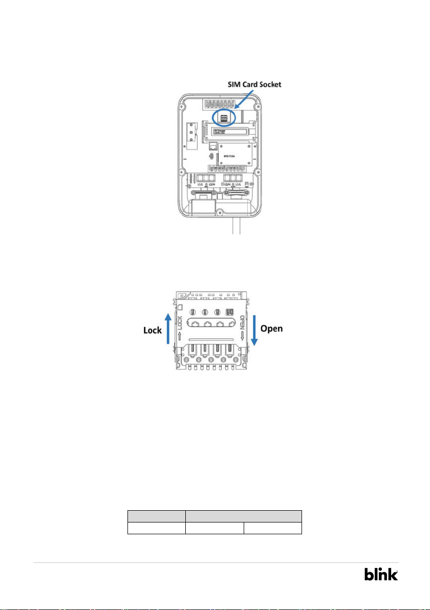
2. Find SIM card socket
Figure 2-2 Position of SIM card socket
3. Insert SIM card
Figure 2-3 SIM card socket and cover Open/Lock direction
3-1. Push down the cover to open SIM card socket.
3-2. Prepare the SIM card. (Use micro-SIM, 15mm x 12mm.)
3-3. Insert the SIM card.
3-4. Close the SIM card socket and push the cover toward lock direction to lock the cover.
3-5. Reassemble the top cover. Please refer to the following torque. SIM card installation is
completed.
Screw Torque
M4 16 kgf.cm 13.88 lb-in
6
Basic/Smart/Intelligent Charger-32A Installation Manual Rev. 4.0
BlinkCharging.com • (888) 998.2546
©2021 Blink Charging Co. • NASDAQ: BLNK
2.4 Install the Charge Point
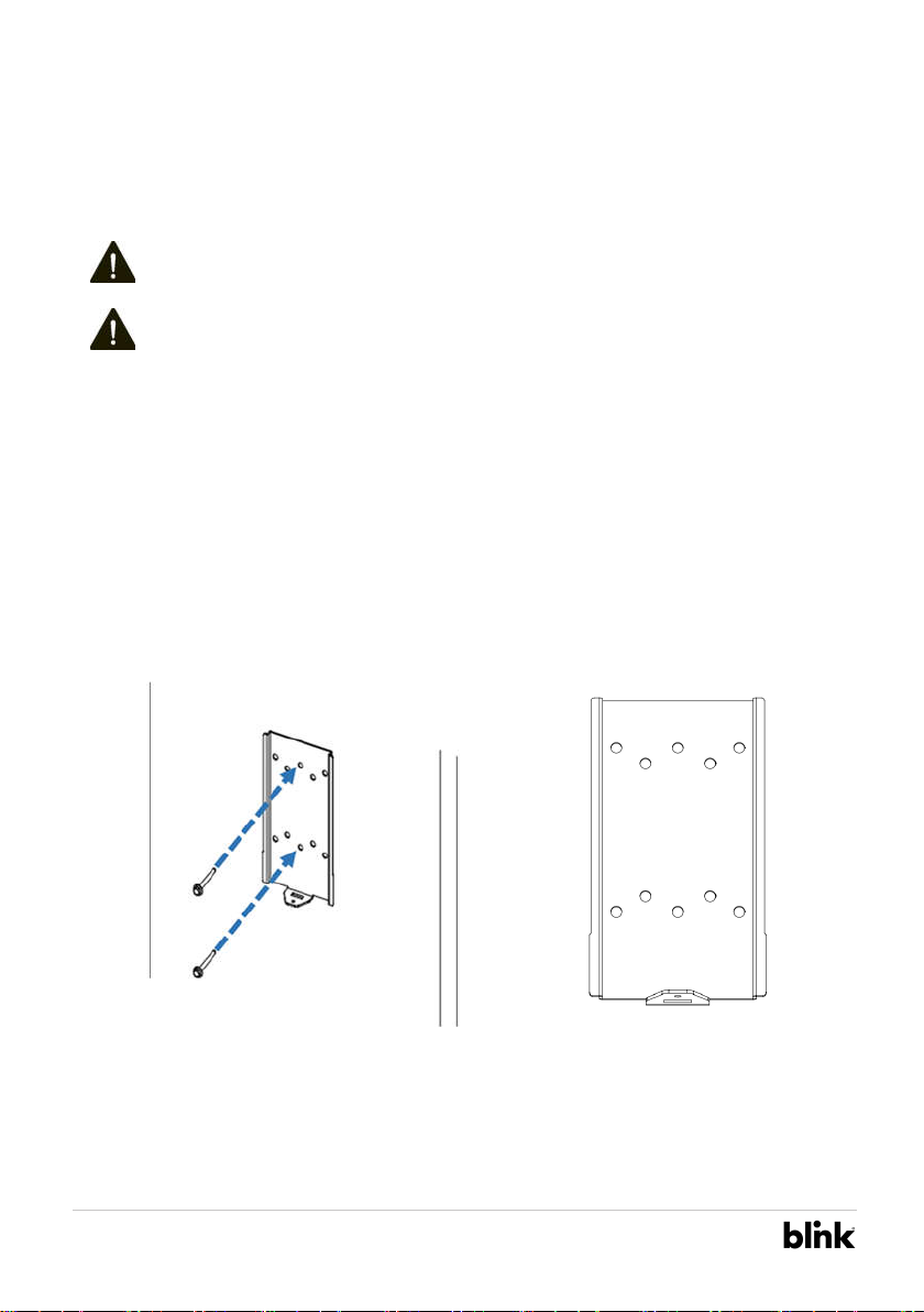
1. Secure the main body mounting bracket to the wall with appropriate screw.
Follow applicable accessibility requirements for the mounting position. The unit shall be stored
or located at a sufficient height.
For indoor use: The unit shall be mounted at a sufficient height from the floor between 18
inches (450 mm) and 4 feet (1.2m).
For outdoor use, it is not lower than 24 inches (600 mm) and not higher than 4 feet (1.2m).
The mounting bracket has ten screw holes. If only two screws be used to secure the mounting
bracket, the screws should pass through the middle two screw holes of the mounting bracket.
The other screw holes are reserved for the user.
Figure 2-4 Secure mounting bracket Figure 2-5 Screw holes of mounting bracket
Screw suggestion:
A. For masonry walls, use M6 mechanical screws. (Commercially Available)
DANGER: Disconnect power at the circuit breaker before installation.
CAUTION: Before mounting determine the suitable mounting location. The unit must
be fixed to a wooden or masonry/concrete wall using hardware that is appropriate
for the surface. Do not install on drywalls, wall boards or thin plywoods. The fixing
point must be capable of supporting the weight of the unit.
7
Basic/Smart/Intelligent Charger-32A Installation Manual Rev. 4.0
BlinkCharging.com • (888) 998.2546
©2021 Blink Charging Co. • NASDAQ: BLNK

B. For finished walls supported by wood studs, use
1/4”or
M6 tapping screws.
(
Commercially available
)
C. Please refer to the following torque. The actual torque is according to the wall material.
Screw Torque
M6 25 kgf.cm min 21.7 lb-in min
#12 25 kgf.cm min 21.7 lb-in min
8
Basic/Smart/Intelligent Charger-32A Installation Manual Rev. 4.0
BlinkCharging.com • (888) 998.2546
©2021 Blink Charging Co. • NASDAQ: BLNK
2. Mount charge point onto mounting bracket and lock the screw.
2-1. Put the charge point on the mounting bracket.
2-2. Fix the charge point on mounting bracket by M4 screw and screw washer.
2-3. Please refer to the following torque.
Screw Torque
M4 16 kgf.cm 13.88 lb/in
Figure 2-6 Charge point and mounting bracket
Figure 2-7 Tighten M4 screw
9
Basic/Smart/Intelligent Charger-32A Installation Manual Rev. 4.0
BlinkCharging.com • (888) 998.2546
©2021 Blink Charging Co. • NASDAQ: BLNK
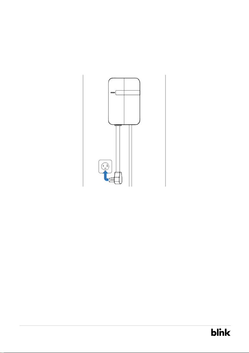
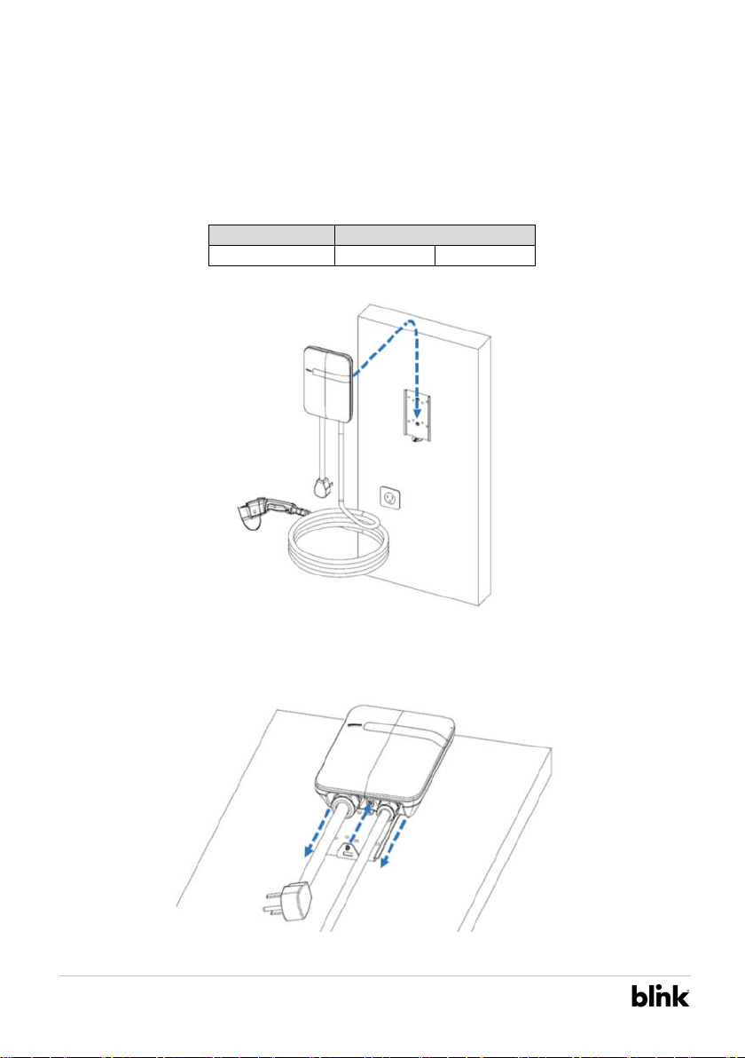
3. Plug in the power cord. (for BC3/SC3 ONLY)
The outlet should be located at 20-26 inch from the ground. Refer to the installation
template to decide where to install the charge point.
Figure 2-8 Plug in the power cord
10
Basic/Smart/Intelligent Charger-32A Installation Manual Rev. 4.0
BlinkCharging.com • (888) 998.2546
©2021 Blink Charging Co. • NASDAQ: BLNK
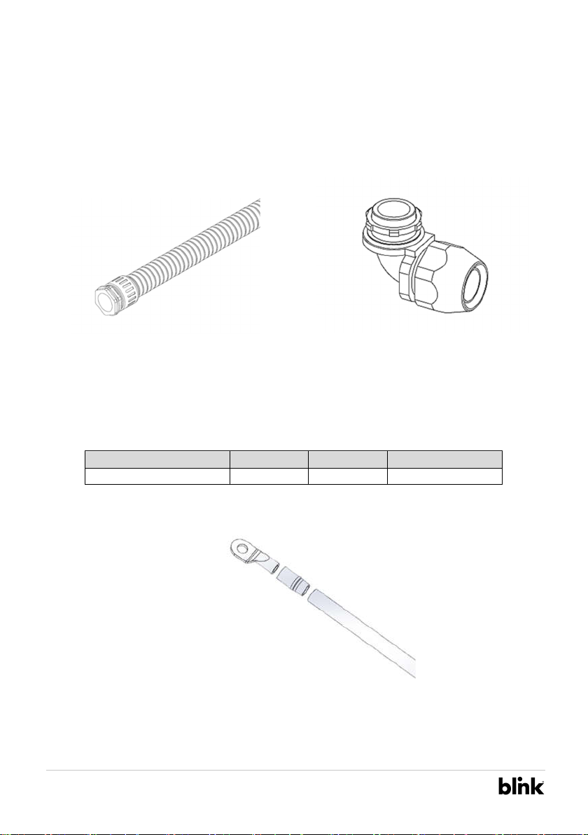
2.5 Input cord connection (for IC3 only)
1. Choose the appropriate conduit in accordance with all applicable state, local and national
electrical codes and standards.
Figure 2-9 Conduit. Figure 2-10 Right angle conduit
2. Clamp copper terminal to connect copper wire. The clamp point is covered by heat shrink
tube for protecting.
2-1 Refer to following wire specification. Use conductor type other than RHH, RHW and RHW-
2 with outer covering.
Model Terminal Conductor Rating
Intelligent Charger-32A L1, L2, G 8 AWG 90C copper wire
Figure 2-11 Copper terminal, heat shrink tube and copper wire.
3. Electrical wiring to the charge point.
3-1. Disassemble top cover.
11
Basic/Smart/Intelligent Charger-32A Installation Manual Rev. 4.0
BlinkCharging.com • (888) 998.2546
©2021 Blink Charging Co. • NASDAQ: BLNK

3-2. Use Philips screwdriver to release terminal screws.
3-3. Fold the wire end to pass through the conduit and insert them into the input hole.
3-4. Fix the copper wire on the corresponding terminal block. The wiring instruction is printed
in front of the terminal block (L1/L2/G).
3-5. Use the following torque to connect the wire terminal to the terminal block.
Screw Torque
M4 16 kgf.cm 13.88 lb-in
3-6. The recommended terminal specifications are as following.
Figure 2-12 Input wiring
Terminal Dimension(mm)
W ≤ 9.5
d2 4-6.4
12
Basic/Smart/Intelligent Charger-32A Installation Manual Rev. 4.0
BlinkCharging.com • (888) 998.2546
©2021 Blink Charging Co. • NASDAQ: BLNK
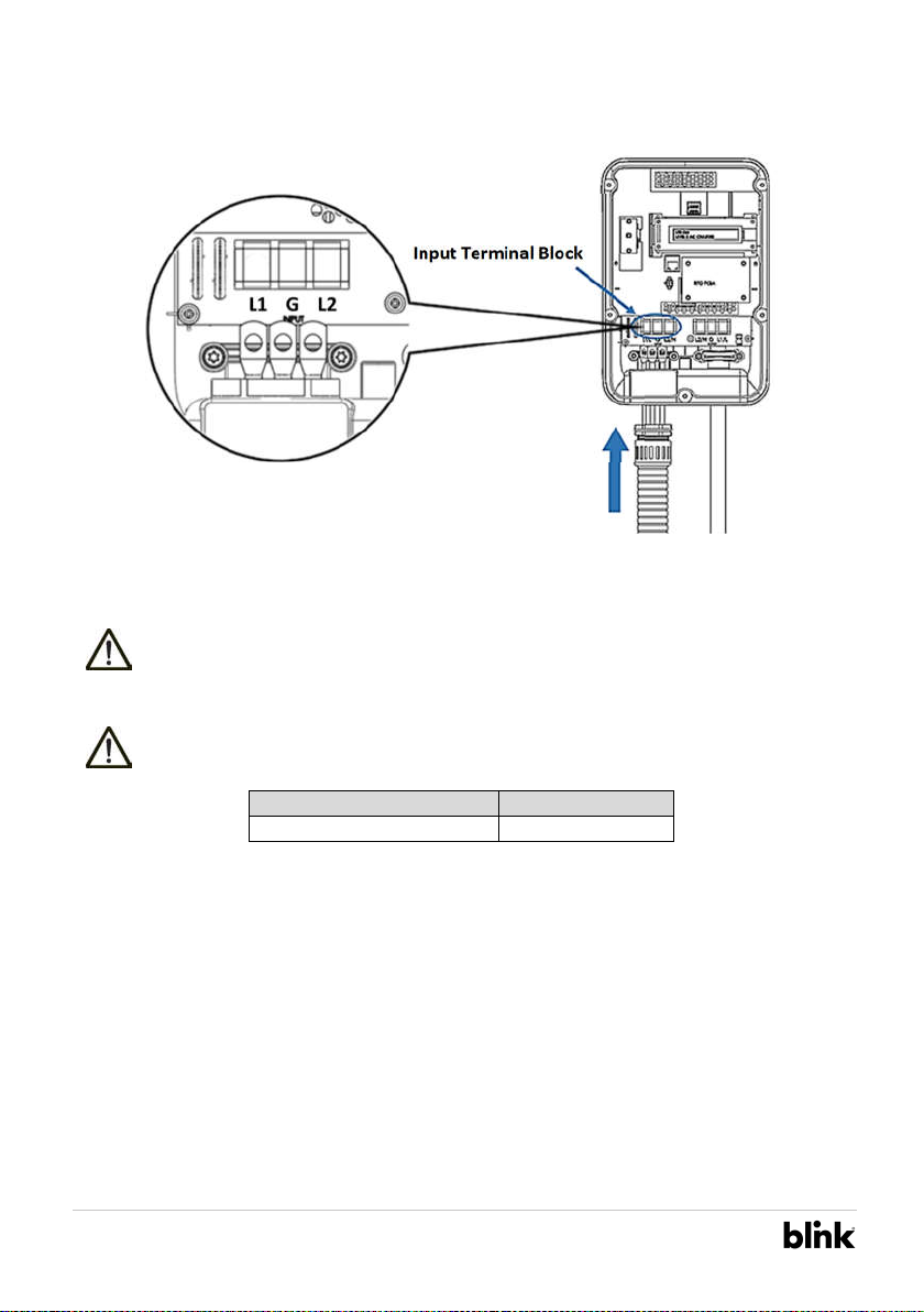
Figure 2-13 Input wiring
Model Current Rating
Intelligent Charger-32A 32 A
CAUTION: To reduce the risk of fire, connect only to a circuit provided with 40
amperes maximum branch circuit overcurrent protection in accordance with the
National Electrical Code, ANSI/NFPA 70, and the Canadian Electrical Code, Part I,
C22.1.
CAUTION: If this unit is installed outdoors, the outlet must be rated for outdoor
installation. The outlet must be installed properly to maintain the proper NEMA
rating of the enclosure.
Input Terminal Block
13
Basic/Smart/Intelligent Charger-32A Installation Manual Rev. 4.0
BlinkCharging.com • (888) 998.2546
©2021 Blink Charging Co. • NASDAQ: BLNK

3-7. Secure the conduit on the enclosure. Please refer to the following torque.
Conduit Torque
1 “ 35 kgf.cm 30.36 lb-in
3-8. Reassemble top cover. Please refer to the following torque.
Screw Torque
M4 16 kgf.cm 13.88 lb-in
14
Basic/Smart/Intelligent Charger-32A Installation Manual Rev. 4.0
BlinkCharging.com • (888) 998.2546
©2021 Blink Charging Co. • NASDAQ: BLNK
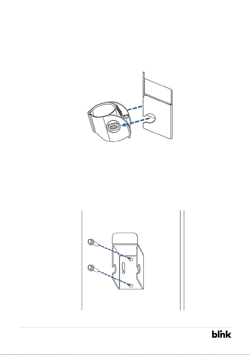
2.6 Install the Holster
1. Separate the holster from hook.
Figure 2-14 Separate the holster
2. Fasten the hook on the wall with appropriate screws.
2-1. For finished walls supported by wood studs, use #12 tapping screws (x2).
2-2. The recommend torque is 25 kgf.cm (21.7 lb-in).
Figure 2-15 Secure the hook
15
Basic/Smart/Intelligent Charger-32A Installation Manual Rev. 4.0
BlinkCharging.com • (888) 998.2546
©2021 Blink Charging Co. • NASDAQ: BLNK
This manual suits for next models
2
Table of contents
Other B-Link Batteries Charger manuals

B-Link
B-Link DS Series Manual

B-Link
B-Link SEMACONNECT 7 Series User manual

B-Link
B-Link bluecorner PQ 150 User manual

B-Link
B-Link DS Series Manual

B-Link
B-Link IQ 200 User manual

B-Link
B-Link TP-EVPD-30kW User manual

B-Link
B-Link 6 Series User manual

B-Link
B-Link SemaConnect US Manual

B-Link
B-Link Wall Mount Charging System User manual

B-Link
B-Link MQ 200 User manual


