B-Link SemaConnect US Manual

A Blink Charging Company
COPYRIGHT © 2021Reserves the right to make changes to this product without further notice.
30kW Wall Mount
DC Fast Charger
User Manual & Installation Instructions
US
Model

CONTENT
Introductions ............................................................................. 1
Features .................................................................................... 1
Applications ............................................................................... 1
1. Basic User Interface ............................................................... 2
.......................................................................... 3
...................................................... 3
2.2 DW30 Version Description ................................................ 5
2.2 LED Indication and Operation Status ................................ 5
2.3 Dimmensions .................................................................. 6
2.4 Direction of cooling Airflow .............................................. 7
3. Installation Instruction ........................................................... 8
3.1 Before Installation ............................................................ 8
3.2 Grounding and Safety Requirement .................................. 9
3.3 Unpack the charger ........................................................ 11
3.4 Recommended Tools for Installation and Inspection........ 13
3.5 Installation Procedure .................................................... 14
3.6 Installation Inspection & Commissioning ........................ 19
4. NetworkSetting ................................................................... 22
4.1 Wi-Fi NetworkSetting .................................................... 22
4.2 3G/4G Setting ................................................................ 24
4.3 Time setting .................................................................. 26
5. Operation Process ................................................................ 28
5.1 Operating Sequence ....................................................... 28
5.2 Operating Procedure ...................................................... 28
5.3 Troubleshooting ............................................................ 33
5.4 StatusCodes ................................................................. 33
6. Maintenance ........................................................................ 49
6.1 General Maintenance...................................................... 49
6.2 Replacement Kitsand Accessories ................................. 51
7. Limited Product Warranty...................................................... 52
Appendix- Packagelist............................................................. 54
semaconnect.com

Introductions
The Wall Mount DC Fast Charger is the top choice to power battery electric vehicles
(BEV) and plug-in electric vehicles (PHEV). It is designed for quick charging in both
public and private locations, such as retail and commercial parking spaces, fleet
charging stations, highway service areas, workplace, residence, etc.
The Wall Mount DC Fast Charger has the advantage of easy installation. The
wall-mounted design and pluggable power modules realize flexible and cost-effec -
tive installation for different types of locations. The DC Wall-Mounted charger also
has network communication capability. It is able to connect with remote network
systems and provide drivers of electric cars real-time information, such as the
location of charging stations, charging progress and billing information. The Wall
Mount DC Fast Charger has a clear user interface with function buttons, safety cer -
tifications and an excellent waterproof and dust proof design to provide the best
choice for outdoor environments.
Features
• Wall-Mounted design and pluggable power modules make installation easy and
flexible.
• Offers customers the convenience of start/stop charging control from an autho -
rized RFID smart card or mobile APP.
• Built on latest industry standards for DC charging.
• Carries an outdoor rating capable of withstanding solid and liquid intrusions in
outdoor settings making the unit more stable and highly reliable.
• Provides a high-contrast, screen interface with multi-function buttons.
Applications
• Public and private parking areas
• Community parking areas
• Parking areas of hotels, supermarkets and shopping malls
• Workplace parking areas
• Charging stations
• Highway rest areas
1semaconnect.com
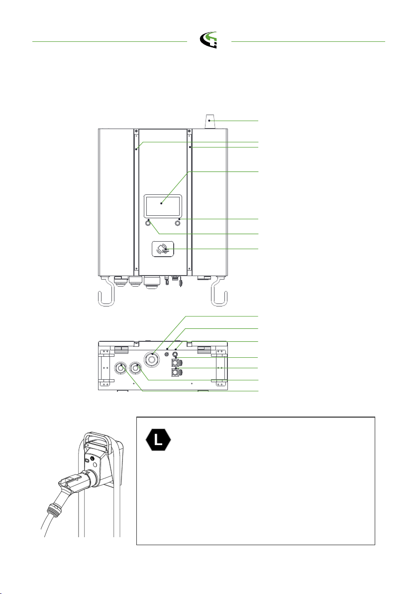
1. Basic User Interface
Antenna
Indication Light
7" Information Screen
Right Button
Left Button
RFID Card Reader
• Charging Status
• Alarm information
• User Authorization
Key Switch (Power On/Off)
Emergency Stop
USB Port
RJ45 Port
Charging Cable Outlet
Charging Cable Outlet
AC Cable Inlet
Main unit :
Notice: According to EN-17186 requirement, this
document lays down harmonized identifiers for pow -
er supply for electric road vehicles. The requirements
in this standard are to complement the informational
needs of users regarding the compatibility between
the EV charging stations, the cable assemblies and
the vehicles that are placed on the market. The
identifier is intended to be visualized at EV charging
stations, on vehicles, on cable assemblies, in EV
dealerships and in consumer manuals as described.
2semaconnect.com

3
Model Name DWWx301 Series
AC
INPUT
Voltage Rating 3Φ480 Vac (+10%, -15%).
Input current 40A
Electrical Distribution 3P+ N +PE (Wye Configuration)
Power Grid System TN / TT
Frequency 50/60Hz
Max. Input Power 33 kVA
Power factor > 0.99
Efficiency > 94%
DC
OUTPUT
Output voltage range CHAdeMO: 150 ~ 500 Vdc
CCS1: 150 ~ 950 Vdc
Max. output current CHAdeMO & CCS1: 500Vdc@60A
CCS1: [email protected]
Max. output power 30kW
Voltage accuracy +/- 2%
Current accuracy +/- 2%
User Interface
Display 7-inch LCD
Button
Right Button : Select charging
connector. (*Not applicable to this
model)
Left Button : Home / Stop charge
User Authorization
RFID: support ISO 14443A/B, ISO
15693, FeliCa Lite-S (RCS966)
OCPP, 2D barcode, APP, Mobile
Payment
Backend support OCPP 1.6JSON
Display information *Charging process and status
*Status codes
Electrical Isolation Isolation between input and output
Standby Power < 100W
semaconnect.com

4
Communication External Ethernet/4G/Wi-Fi
Internal CAN Bus / RS485
Input Protection OVP, OPP, UVP, SPD
Output Protection SCP,OCP, OVP, LVP, OTP, IMD
Internal Protection OTP, AC contactor detection, DC contactor detection,
Fuse detection
Load Management Via OCPP 1.6JSON
Operation
conditions
Operation Temperature -30 °C to 50°C
Storage Temperature -40 °C to 85°C
Relative Humidity 5%~95% RH, non-condensing
Altitude 2000 M
Regulations
Safety UL2202, UL2231-1/-2
EMI/EMC FCC Part 15B
Charging Interface
CHAdeMO : Ver 1.2
CCS1 : DIN70121 (ISO15118 by
2021/Q4)
Mechanical
Specifications
Dimensions (WxDxH mm) 610 x 230 x 690
Weight (typ.) Dual Guns:88kg
Single Gun:80kg
DC Charging Connector Refter to Chapter 2.2 Table
Charging Cable Length <5M, Optional other length
Charging Cable Number 2
Input cable and connection Not included
Cooling Forced Air
Ingression Protection IP55
Anti-vandalism IK10 (does not include LCD & RFID
cover)
semaconnect.com
5
2.2 LED Indication and Operation Status
Status LED Left Indicator Right Indicator
Standby Green Green
Fault Red Red
Charging Blue Blue
2.2 DW30 Version Description
The DW30 seriers are available in different versions depending on the charging
connectors, below table shows the available combinations, the coresponding posi -
tion of charging connectors are indicated from left to right in the view of front char -
ger.
Version CHAdeMO CCS1
DWWx301 J0U XX
DWWx301 J00 X-
DWWx301 U00 -X
0 : none
1 : IEC 62196-2 Type 1/SAE J1772 Plug
2 : IEC 62196-2 Type 1/SAE J1772 Socket
3 : IEC 62196-2 Type 2 Plug
4 : IEC 62196-2 Type 2 Socket
5 : GB/T AC Plug
6 : GB/T AC Socket
7:CCS2 AC Plug
J : CHAdeMO
U : Natural cooling CCS1 combo
V : Liquid cooling CCS1 combo
E : Natural cooling CCS2 combo
F : Liquid cooling CCS2 combo
G : GBT DC
semaconnect.com
6
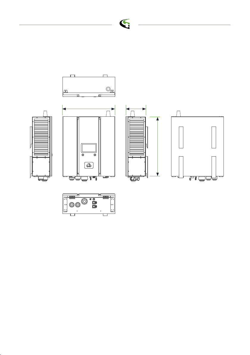
2.3 Dimmensions
MainSize ofCharger:
610 230
690
(Unit: mm)
semaconnect.com
7
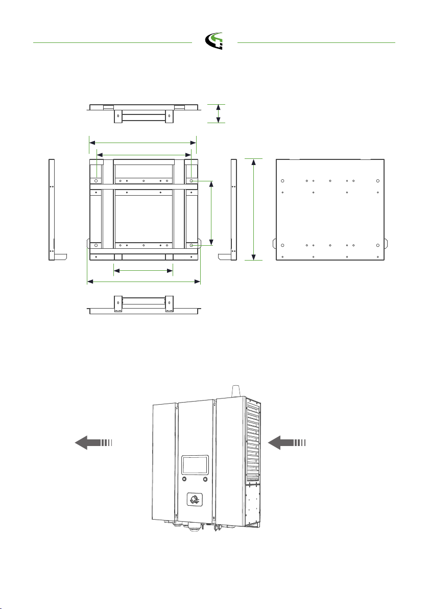
Wall-Mounted Bracket:
2.4 Direction of cooling Airflow
Air OutAir In
580
97
542
510
610
317
345
semaconnect.com

8
• Read all the instructions before using and installing this product.
• Do not use this product if power cable or charging cable have any damage.
• Do not use this product if the enclosure or charging connector are broken or
open or if there is damage.
• Do not put any tool, material, finger or other body part into the charging connec -
tor or EV connector.
•
•
• Power feed must be 3 Phase Wye configuration with TN(-S)/TT grounding sys -
tems.
• In the installation of TN(-S) system: the neutral (N) and the PE of the power dis -
tribution are directly connected to the earth. The PE of the charger equipment is
directly connected to the PE of power distribution and separate conductor for PE
and neutral (N).
• In the installation of TT system: the neutral (N) and the PE of the power distribu -
tion are directly connected to the earth. The PE of the charger equipment is iso -
lated to the PE of power distribution to the earth.
• The capacity of power supply should be higher than 33.0kVA in order to function
correctly.
• The product should be installed in free air area and keep at least 30cm clearance
distance to all air vent of the product.
• Need sufficient space for product installation and maintenance, please keep not
less than 60cm clearance distance from all around the product.
3. Installation Instruction
3.1 Before Installation
Warning: The product should be installed only by a licensed contractor
and/or licensed technician in accordance with all building codes, elec -
trical codes and safety standards.
Warning: The product should be inspected by a qualified installer prior
to initial use. Under no circumstances will compliance with the infor -
mation in this manual relieve user of his /her responsibilities to comply
with all applicable codes and safety standards.
semaconnect.com
9
• The product must be connected to a grounded, metal, permanent wiring system.
Connections shall comply with all applicable electrical codes.
• Ensure no power is connected at all times when installing, servicing, or maintain -
ing the charger.
• Use appropriate protection when connecting to main power distribution network.
• Use appropriate tools for each task.
3.2 Grounding and Safety Requirement
CAUTION: The disconnect switch for each ungrounded conductor of
AC input shall be provided by installation contractor or technician in
accordance with the National Electric Code, ANSI/NFPA 70.
CAUTION: A cord extension set or second cable assembly shall not be
used in addition to the cable assembly for connection of the EV to the
EVSE.
NOTICE
It is recommended to conduct WI-Fi and 4G signal strength while
charger installation. The RSSI (Received Signal Strength Indication)
value is considered as good as higher than -65dBm. Poor connec -
tion quality might interrupt charging process or data transaction.
semaconnect.com

10
3.2.1 Service Wiring
• Ground Connection
Always connect the Neutral at the service to Earth Ground. If ground is not pro -
vided by the electrical service then a grounding stake must be installed nearby.
The grounding stake must be connected to the ground bar in the main breaker
panel and Neutral connected to Ground at that point.
• 480Vac (Line to Line) Three-Phase
CAUTION!
tsaFCDtnuoMllaWeht,dirgrewopnoitcennoc-eyWmorfdeefsisihT
Charger can connect to L1, L2 or L3, and Neutral. Earth ground must be
connected to neutral at only one point, usually at the breaker panel.
480V Three-Phase Wiring Connection
WARNING!
Earth Connection is Essential!
PE
277V 277V
277V
480V
Neutral
DANGERS
Be Aware of High Voltage!
L3
L1
L2
semaconnect.com
11
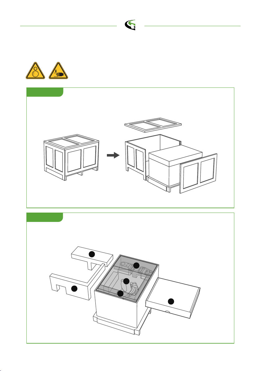
3.3 Unpack the charger
Remove the surrounding boards
STEP 1.
STEP 2.
Remove the packaging film and the paper cover. Accessories (wall mount)
are packed in a carton.
WARNING!
Charger weight might >80Kg!
Be careful during unpack process.
1
3
1
2
3
2
Accessories
Box
semaconnect.com

12
Remove the surrounding cardboard and film. Take out the Charger and Gun
holders.
STEP 3.
Gun holders
Charger
Accessories Box
1
2
1
2
Accessories
Wall mount
1
2
1
2
semaconnect.com

13
3.4 Recommended Tools for Installation and
Inspection
3.4.1 Recommended Tools for Installation
Type Description
Philips Screwdriver No. 2 and 3
Shifting Wrench 8" (24mm)
Ball-Head Hex Key 2.5mm and 5mm
Socket Screwdriver No. 8 ,10 and 17
Electrical Tape Black / 15mm Width
AC Input Cable AWG#4 (21.15mm2) Cable x 5 (L1,L2,L3,N,PE)
Ring Terminal
1. AWG#4 x 5 (L1,L2,L3,N,PE)
2. Ring Terminal inner diameter is 6.4mm;
outer diameter is 16.5mm for L1, L2, L3 and N
3. Ring Terminal inside diameter is 5.3mm;
outer diameter is 12mm for PE
Crimping Pliers for Ring Terminal
Machine Drill
Level Ruler
3.4.2 Recommended Tools for Inspection & Commissioning
Type Description
EV or EV Simulator Meet CHAdeMO/CCS1 standard
Multiple Meter 1000V
Current Probe 100Amp
RFID Authorized Card
RFID No Valid Card
Door Key
Laptop or PC & CAT6 cable For Charger Configuration
Wi-Fi /4G signal quality checker Recommended
semaconnect.com
14
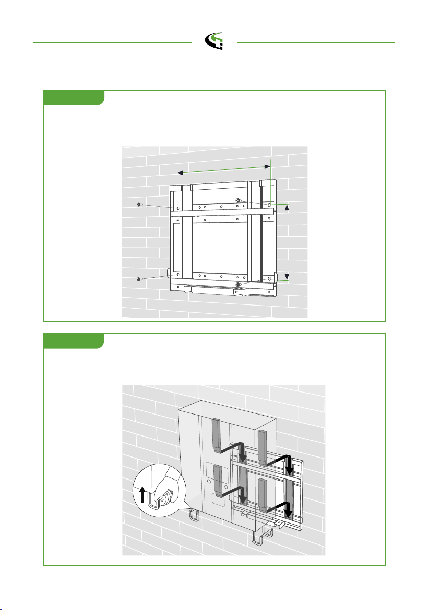
3.5 Installation Procedure
Place the wall-mounted bracket between 600mm (24 inches) and 1.2m (4
feet) above the floor, and then attach 4 pcs 3/8 ”expansion screws to the
wall-mounted bracket. (Unit: mm)
Unit: mm
STEP 1.
STEP 2.
Install the four tenons on the rear side of the charger into the grooves on the
wall-mounted bracket.
510
345
SCALE 0.500
semaconnect.com

15
Screw 2 sets M6 screws to the bottom of the charger to fix the charger on the
bracket.
Keep the hook-shape holders as cable holder or disassemble them if not
necessary.
STEP 3.
STEP 4.
semaconnect.com

16
Four screws of the Gun Holder must be disassembled at the circles below
outlined.
STEP 1.
Gun Holder screw location
The hole position of the Gun Holder
Unit: mm
Installing the Gun Holder
etairporppaehttaesabredloHnuGecalpdnarevocredloHnuGehtevomeR
height between 600mm (24 inches) and 1.2m (4 feet), and then attach 2 pcs
5/16”expansion screws to the Gun Holder base, then assembly the cover
back.
STEP 2.
Gun Holder screw location
120
semaconnect.com

17
Installing Cables
Remove 2 of M5 screws and push the button (marked as no.3) to open front
cover :
STEP 1.
Please use XLPE power cables or equivalent for AC input connection, power
cable outer diameter is between 32 and 40mm. If XLPE cable is not available,
please use conduit hub and conduit size M50 to prevent electrical hazards
and do best water proof. the requirements of conduit shall be according to
EN61386-24 or followed local laws and regulations.
Each wire shall be crimped with the corresponding terminal before feeding. L1,
L2, L3 and N shall chose terminals with inner diameter 6.4mm and outer diam -
eter 16.5mm, PE shall chose terminals with inner diameter 5.3mm and outer
diameter 12mm. And then feeding the cable from bottom side and passing
through the cable gland.
STEP 2.
1
2
3tightentighten
loosen
loosen
OD
ID
Terminal
1
3
2
semaconnect.com

18
Fasten L1, L2, L3 and N wires onto the 4P terminal with M6 screws, torque
,wercs5MhtiwrabsubehtoteriwEPnetsaF.sces51-5/mc.fgK03:ecrof
torque force: 27Kgf.cm/5-15 secs. Keep proper length of each wires then fas -
ten cable grand.
Fasten L1, L2, L3 and N to an external beaker. Recommended breaker spec.:
rated current shall be 50A, B Curve type; with max. Residual leakage current
(RCD) shall be 30mA, type A.
STEP 3.
STEP 4.
L1L2L3N
PE AWG#4 x 4
Turn on the power source and operation screen will be ready within 30
seconds.
STEP 5.
Not following installation instruction will cause charger damage.
A 50A NFB with 30mA RCD-Type A is recommended.
semaconnect.com
Table of contents
Other B-Link Batteries Charger manuals

B-Link
B-Link bluecorner PQ 150 User manual

B-Link
B-Link 6 Series User manual

B-Link
B-Link DC Fast Charger User manual

B-Link
B-Link Wall Mount Charging System User manual

B-Link
B-Link SEMACONNECT 7 Series User manual

B-Link
B-Link WE-30C User manual

B-Link
B-Link DS Series Manual

B-Link
B-Link Basic Charger-32A User manual

B-Link
B-Link HQ 200 User manual

B-Link
B-Link MQ 200 User manual


Popular Batteries Charger manuals by other brands

FRONIUS
FRONIUS Acctiva Twin operating instructions

FRONIUS
FRONIUS Selectiva 4.0 30 kW operating instructions

Meanwell
Meanwell PB-1000 instruction manual

Prologix
Prologix Solar PL3740 Operator's manual

Mid Ocean Brands
Mid Ocean Brands MO6476 user manual

Yard Works
Yard Works 060-1990-2 instruction manual


