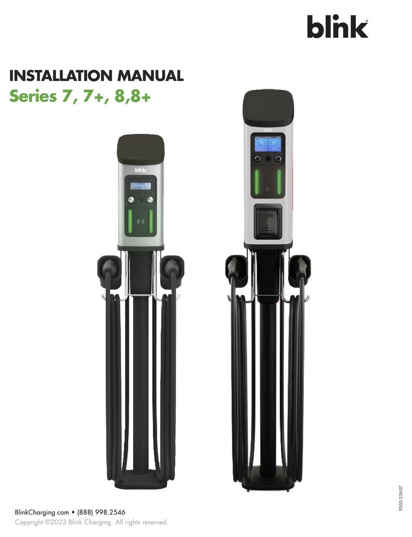
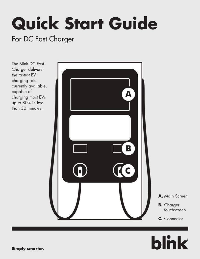
B-Link DS Series Manual

COPYRIGHT © 2021 Reserves the right to make changes to this product without further notice.
W84A99900255-RB1
Emergency
Stop
DC EVSE 180KW
Standalone Fast Charger
User Manual & Installation Instructions
DS Series
UL
Model
BlinkCharging.com •(888) 998.2546
300A
PD02-23V-03

CONTENT
Introductions .............................................................................. 1
Features ..................................................................................... 1
Applications................................................................................ 1
1. Basic User Interface................................................................ 2
........................................................................... 3
....................................................... 3
2.2 DS180 Version Description ............................................... 6
2.3 LED Indication and Operation Status ................................. 7
2.4 Dimensions ..................................................................... 8
2.5 Direction of cooling Airflow .............................................. 8
3. Installation Instruction ........................................................... 9
3.1 Before Installation ............................................................ 9
3.2 Grounding and Safety Requirement................................. 15
3.3 Install Sensor Board for Safely Shutting Down................. 17
3.4 Unpack the charger ........................................................ 21
3.5 Recommended Tools for Installation and Inspection........ 25
3.6 Installation Procedure .................................................... 27
3.7 Installation Inspection & Commissioning ........................ 37
4. Network Setting ................................................................... 40
4.1 Wi-Fi NetworkSetting .................................................... 40
4.2 3G/4G Setting................................................................. 42
4.3 Time setting .................................................................. 44
5. Operation Process................................................................. 46
5.1 Operating Sequence ....................................................... 46
5.2 Operating Procedure....................................................... 46
5.3 Troubleshooting ............................................................ 52
5.4 StatusCodes.................................................................. 60
6. Maintenance ........................................................................ 81
6.1 Before Maintenance........................................................ 81
6.2 General Maintenance...................................................... 81
6.3 Replacement Kitsand Accessories ................................. 83
BlinkCharging.com •(888) 998.2546

7. Limited Product Warranty...................................................... 84
Appendix 1 - Packagelist.......................................................... 86
Appendix 2 - Breaker Lock Installation ...................................... 87
Appendix 3 - Preventive Maintenance Check List........................ 88
BlinkCharging.com •(888) 998.2546

1
Introductions
Features
• Pluggable power modules make installation easy and flexible.
• Offers customers the convenience of start/stop charging control from an
authorized RFID smart card or mobile APP.
• Built according to the latest industry standards for DC charging.
• Carries an outdoor rating capable of withstanding solid and liquid intrusions in
outdoor settings making the unit more stable and highly reliable.
• Provides a high-contrast, screen interface with multi-function buttons.
Applications
• Public and Private Parking Areas
• Community Parking Areas
• Parking Areas of Hotels, Supermarkets and Shopping Malls
• Workplace Parking Areas
• Charging Stations
• Highway Rest Areas
The Standalone DC Fast Charger is the top choice to power battery electric vehicles
(BEV) and electric vehicles (PHEV). It is designed for quick charging in both public
and private locations, such as retail and commercial parking spaces, fleet charging
stations, highway service areas, workplace, residence, etc.
The Standalone DC Fast Charger has the advantage of easy installation. The
pluggable power modules realize flexible and cost-effective installation for different
types of locations. The DC Standalone charger also has network communication
capability. It is able to connect with remote network systems and provide drivers
of electric cars real-time information, such as the location of charging stations,
charging progress and billing information. The Standalone DC Fast Charger
has a clear user interface with function buttons, safety certifications and an
excellent waterproof and dust proof design to provide the best choice for outdoor
environments.
BlinkCharging.com •(888) 998.2546

2
Emergency
Stop
1. Basic User Interface
Antenna for Wi-Fi & 3G/4G
LED Indication
7" Information Screen
nottuBtfeL¬tuBthgiR
Credit Card Payment System
(Optional)
• Charging Status
• Alarm information
• User Authorization
Left DC Connector
Right DC Connector
*The connectors installed on the
EVSEmay vary depending on the
model(section 2.2)
BlinkCharging.com •(888) 998.2546

3
Model Name DSWX182 Series
AC
INPUT
Voltage Rating 3Φ480Vac(+10%,-15%)
Max.InputCurrent233A @277Vac
274A@ 235Vac
Electrical Distribution
Power Grid System TN/TT
Frequency50/60Hz
Max.Input Power 196kVA
Power Factor > 0.99
>94%, at optimize V/Ipoint
SCCR35kA, optional for 65kA
DC
OUTPUT
Output Voltage RangeDC 150 ~950V (CCS)
DC 150 ~500V (CHAdeMO)
Maximum OutputCurrent
**CCS1
300A@150Vdc ~ 600Vdc when
output voltage up to 950 Vdc
the output current is 190A
**CHAdeMO
120A@150Vdc ~ 500Vdc
Maximum Output Power 180KW
Simultaneously output
mode
Each connector will get 50%
output power when plug in
simultaneously; And one of
two connected vehicles is fully
charged, all power is diverted to
must be removed from vehicles).
*CHAdeMO max. is 60KW
BlinkCharging.com •(888) 998.2546

4
Voltage Accuracy ±2%
CurrentAccuracy ±2%
Electrical Isolation Isolation between Input and Output
Standby Power < 100W
Communication External Ethernet, Wi-Fi and 3G or 4G
Internal CAN Bus/ RS485
Input Protection OVP, OCP, OPP, UVP, RCD, SPD
Output Protection OCP, OVP, LVP, OTP, IMD
Internal Protection OTP, AC contactor detection, DC contactor detection, Fuse
detection
Load Management Via OCCP 1.6 JSON
User Interface &
Control
Display 7-inch LCD
Button
Right Button : Selectcharging
connector.
Left Button : Home / Stop charge
User Authentication
RFID : Support ISO 14443A/B, ISO
15693, FeliCa Lite-S (RCS966),
Backend OCPP :2D barcode, APP,
Mobile Payment
Backend Support OCPP 1.6 JSON
Environmental
Conditions
Operation Temperature
-30°C to 50°C (-22°F to 122°F), will
derating from 50°C (122°F) and
above
Storage Temperature -40°C to 70°C (-40°F to 158°F)
Relative Humidity 5%~95% RH, non-condensing
Altitude≤2000m(6560 ft)
Regulations
Safety UL2202,UL2231
EMI/EMC
FCC CFR Title 47 Part 15
Subpart B: 2020
ANSIC63.4:2014
ICES-003:2020 Issue 7
Charging Interface CHAdeMO Ver 1.2
CCS DIN 70121
BlinkCharging.com •(888) 998.2546

5
Mechanical
Dimensions (WxDxH mm)800x650x1900mm (32x26x75
inches )
Weight (typ.)<500kg (1102 lbs) withtwo
charging guns
DC Charging Connector Refter to Chapter 2.2 Table
Cooling Fan Cooling
Ingression Protection NEMA 3R
Anti-vandalismIK10, excluding LCD & RFID cover
BlinkCharging.com •(888) 998.2546

6
Emergency
Stop
Left DC Connector Right DC Connector
2.2 DS180 Version Description
The DS180 series are available in different versions depending on the charging
connectors, below table shows the available combinations, the corresponding
position of charging connectors are indicated from left to right in the view of front
charger.
Version Left DC Connector AC Connector Right DC Connector
DSWX182J0U CHAdeMO - CCS1
DSWX182U00 CCS1 - -
DSWX182U0UCCS1 - CCS1
Note: The letter “X”is variance for difference function.
BlinkCharging.com •(888) 998.2546

7
Emergency
Stop
Emergency
Stop
Emergency
Stop
Standby Fault Charging
2.3 LED Indication and Operation Status
Status LED Left Indicator Right Indicator
Standby Green Green
Fault Red Red
Charging Blue Blue
*Left LED for Left Connector, Right LED for RightConnector.
BlinkCharging.com •(888) 998.2546

8
2.5 Direction of cooling Airflow
Emergency
Stop
Air OutAir In
2.4 Dimensions
Main Size of Charger:(Unit: mm)
800 650
1900
BlinkCharging.com •(888) 998.2546

9
• Read all the instructions before using and installing this product.
• Do not use this product if power cable or charging cable have any damage.
• Do notuse this product if the enclosure or charging connector are broken or open
or if there is damage.
• Do notputany tool, material, finger or other body part into the charging connector
or EV connector.
• Do not twist, swing, bend, drop or crush the charging cable. Never drive over it
with a vehicle.
• Power feed must be 3 Phase Wye configuration with TN(-S)/ TT grounding
systems.
• In the installation of TN(-S) system: the neutral (N) and the PE of the power
distribution are directly connected to the earth. The PE of the charger equipment
is directly connected to the PE of power distribution and separate conductor for
PE and neutral (N).
• In the installation of TT system: the neutral (N) and the PE of the power
distribution are directly connected to the earth. The PE of the charger equipment
is isolated to the PE of power distribution to the earth.
• The capacity of power supply should be higher than 196 kVA in order to function
correctly.
• The product should be installed in free air area and keep at least 30cm (12 inches)
clearance distance to all air vent of the product.
• Recommend to keep not less than 100cm (3 ft. 6 in.) clearance distance from all
around the product following NEC table 110.26 condition 2, 151-600V.
3. Installation Instruction
3.1 Before Installation
WARNING:The product should be installed only by a licensed
contractor and/or licensed technician in accordance with all building
codes, electrical codes and safety standards.
WARNING: The product should be inspected by a qualified installer
prior to initial use. Under no circumstances will compliance with the
information in this manual relieve user of his /her responsibilities to
comply with all applicable codes and safety standards.
NOTICE
It is recommended to conduct WI-Fi and 3G/4G signal strength
while charger installation. The RSSI (Received Signal Strength
Indication) value is considered as good as higher than -65dBm.
Poor connection quality might interrupt charging process or data
transaction.
BlinkCharging.com •(888) 998.2546

10
3.1.1 Contractor Safety guide
Introduction
• A safe work environment for everyone - participants, installation and
demolition crews, contractors and subcontractors.
• Ultimately, it is the responsibility of contractors to ensure the safety and safe
work practices of their employees and subcontractors who may be working at
the site on their behalf.
• This guide provides a simple reference guide with basic rules for
implementation. This guide does not outline every single safety standard: it is
designed to be a supplement to participants, contractors and subcontractors.
• Contractors, subcontractors and employees should cooperate with their
employers and other persons in complying with safety regulations and
instructions.
In particular, employees should:
1.
area.
2. Work safely.
3. Notdo anything to endanger themselves or other persons.
4. Use personal protective equipment as required and take reasonable care of
it when it is not in use.
5. Report unsafe activities immediately to supervisorsor the responsible
person in control of the workplace.
6. Report all accidents and dangerousoccurrences to the supervisor
immediately after they happen.
BlinkCharging.com •(888) 998.2546

11
• Setup suitable fencing to isolate the construction
area from outside
• Close and secure all entrances when the site is
unattended
• Hang warning noticesnearby which show the
following information: warning icon and phone
number of person in charge
•
• Keep work areas (including accessways) free from
debris and obstructions
• Keep ground surfaces tidy and flat, to avoid people
tripping or being hurt by tools or other objects
• Stack and store equipment and materials in a tidy
and stable manner
• Regularly clean up and dispose of waste
• Remove all surplus materials and equipment after
completion of work
• Beware of flammable materials and goods. Keep
them away from work areas.
1.Requirements for workplace conditions
2.Cleaning up
3.Fire hazards
BlinkCharging.com •(888) 998.2546

12
• Erect a sunshade or shed to shelter workersfrom
the heat and sun
• Setup cooling equipment, such as exhaust fans
• Make water dispensers available
• Provide suitable protective clothing such as hat,
sunglasses and long sleeves to protect workers
from heat stroke and UV rays
• Secure all scaffoldings, temporary structures,
equipment, and loose materials
• Check and implementSOP to ensure
disconnection of gas supplies, electrical circuits
and equipment
• Inspect worksites to ensure protection against
ingress of water or dust
• Inspect the drainage system for blockages and
remove if found
• Stop all outdoor works exceptfor emergency
works
4.Protection against high temperatures on the worksite
5.Inclement weather
• Only use ladders that meet local safety
regulations
• Do notuse wooden ladders
• When working at height, it is recommended to use
platforms instead of ladders
• If using a platform is notpracticable, a supervisor
should assess the potential risk and provide
safety
6.Ladders
BlinkCharging.com •(888) 998.2546

13
• Avoid working at height by using alternative
tools and methods as far as practicable
• It is strongly recommended to build suitable
scaffolding or workplatforms
• Provide fall arrest systemsfor workers if it is
impracticable to use working platforms
• Secure all materials and tools to prevent them
falling from height
7.Working at height
• protection equipmentfor workers
•
or reinforced plastic when carrying outelectrical
work
• Assign assistants to provide support when
working on ladders
• Check all laddersfor broken rungsor other
defects before use and periodically
• Fully open stepladders when in use
• Do not stand on the top two rungsof a ladder
• Do not overreach when working on a ladder
• Beware of overload restrictions
Country Standards
British BS1129,BS2037,EN131,EATS13/1
USA ANSI A 14.1,ANSI A 14.2,ANSI A 14.5
Australia New
Zealand
AS 1892.2-1922,AS/NZS1892.1,AS/NZS
1892.3
Canada CSA Z11 M81
Common Standards for Ladders
BlinkCharging.com •(888) 998.2546

14
• Have lifting gear and apparatus regularly
• Isolate and cordon off lifting areas to keep out
non-construction personnel
• Ensure that lifting routes do notcross buildingsor
people, and avoid collision with objects
• Do not exceed safe working load limits
• Plan all work
• Turn off power (work with live parts de-energized
whenever possible)
• LOTO (Lock Out, Tag Out)
• Live electrical work permit (input terminals with HV
after door open)
• Use personal protective equipment (PPE)
• Safe workplace conditions and space
• Adhere to other occupational health, safety and
security codes, such as those published by OSHA
8.Lifting operations
9.For on-site workers
Adhere to the following codes:
• NFPA-70E -2021 Sec 110.3 (Electrical Safety in
the Workplace)
• NFPA-70E -2021 Sec 130.4 (ShockRisk
Assessment)
• NFPA-70E -2021 Sec 130.5 (Arc Flash Risk
Assessment)
10.Reference standards
BlinkCharging.com •(888) 998.2546

15
• The product must be connected to a grounded, metal, permanent wiring system.
Connections shall comply with all applicable electrical codes. Recommend the
ground resistance be less than 10 Ω.
• Ensure no power is connected at all times when installing, servicing, or
maintaining the charger.
• Use appropriate protection when connecting to main power distribution network.
• Use appropriate tools for each task.
3.2 Grounding and Safety Requirement
CAUTION: The disconnect switch for each ungrounded conductor of
AC input shall be provided by installation contractor or technician in
accordance with the National Electric Code, ANSI/NFPA 70.
CAUTION: A cord extension set or second cable assembly shall not be
used in addition to the cable assembly for connection of the EV to the
EVSE.
BlinkCharging.com •(888) 998.2546

16
3.2.1 Service Wiring
• Ground Connection
Always connect the Neutral at the service to Earth Ground. If ground is not
provided by the electrical service then a grounding stake must be installed nearby.
The grounding stake must be connected to the ground bar in the main breaker
panel and Neutral connected to Ground at that point.
• 480Vac Three-Phase(Line to Line)
CAUTION!
This is feed from Wye-connection power grid, the Standalone DC Fast
Charger can connect to L1, L2 or L3, and Neutral. Earth ground must be
connected to neutral at only one point, usually at the breaker panel.
480V Three-Phase Wiring Connection
WARNING!
Earth Connection is Essential!
PE
277V 277V
277V
480V
Neutral
L3
L1
L2
DANGERS
Be Aware of High Voltage!
BlinkCharging.com •(888) 998.2546

17
SOR
Circuit Breaker
Sensor BoardSensor Board
3.3 Install Sensor Board for Safely Shutting Down
1. Introduction: To prepare a control board which includes door sensor sensing
function and tilt sensor, also dry contact points for extending wiring to upstream
circuit breaker in order to cut off power immediately when sensors triggered.
This board also has self-test button which uses to verify if it functions properly
no matter in production line or in installation site or during regular maintenance
service.
2. Function Block Diagram:
Door Sensor Signal
Tilt Sensor
Sensor Board
Upstream Circuit Breaker
or
Similar Safety Device
BlinkCharging.com •(888) 998.2546
Other manuals for DS Series
2
This manual suits for next models
4
Table of contents
Other B-Link Batteries Charger manuals
B-Link
B-Link bluecorner PQ 150 User manual
B-Link
B-Link Wall Mount Charging System User manual
B-Link
B-Link DS Series Manual
B-Link
B-Link WE-30C User manual
B-Link
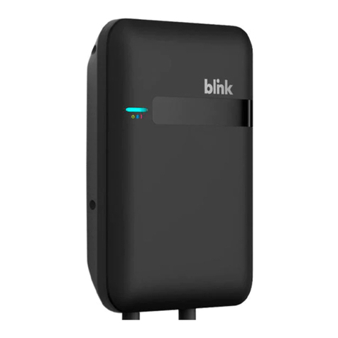
B-Link Basic Charger-32A User manual
B-Link
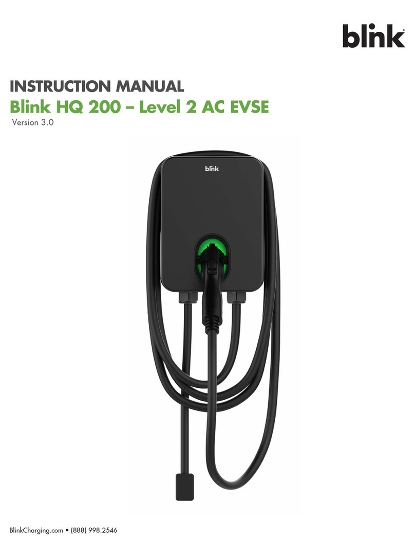
B-Link HQ 200 User manual
B-Link
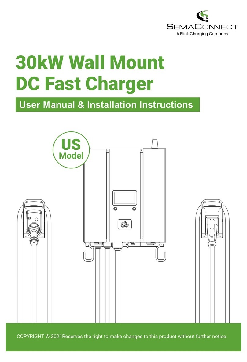
B-Link SemaConnect US Manual
B-Link
B-Link TP-EVPD-30kW User manual
B-Link
B-Link MQ 200 User manual

B-Link
B-Link IQ 200 User manual
