B.M.P. ThermicRoll User manual

AFTER INSTALLING PLEASE FORWARD INSTRUCTIONS TO
THE MAINTENANCE DEPARTMENT OR OWNER
JAMISON DOOR COMPANY
H4494002 REV B
JAMISON-B.M.P.
INDUSTRIAL RAPID DOORS
ThermicRoll® Installation
JAMISON DOOR COMPANY
P.O. BOX 70
HAGERSTOWN, MARYLAND 21741
1-800-532-3667 301-733-3100
INTERNET: http://www.jamisondoor.com
E-MAIL: contact@jamisondoor.com

Installation Instructions
JAMISON DOOR COMPANY
2
H4494002 REV B

Installation Instructions
JAMISON DOOR COMPANY
3
H4494002 REV B
INSTALLATION INSTRUCTIONS INDEX
1. INSTALLATION OVERVIEW ......................................................................................4
2. EQUIPMENT NEEDED...............................................................................................5
3. COLUMNS PREPARATION........................................................................................6
4. TRANSMISSION SHAFT ASSEMBLY........................................................................8
5. LIFTING BAR AND SPACER BAR ASSEMBLY .......................................................10
6. MECHANICAL ASSEMBLY ......................................................................................11
7. PANEL ASSEMBLY..................................................................................................13
8. COUNTERWEIGHT BELT ASSEMBLY....................................................................16
9. CABLE CONNECTIONS...........................................................................................18
10. MOTOR ROTATION .................................................................................................19
11. SET DOOR LIMITS, BRUSHES, AND COVERS......................................................20
12. CONTROL PANEL OVERVIEW................................................................................21
13. CONTROL CARD TERMINAL FUNCTIONS.............................................................22
14. LED FUNCTION........................................................................................................23
15. SETTING THE OPEN AND CLOSE POSITION........................................................24
16. PEDESTRIAN OPEN POSITION SETUP.................................................................26
17. RADIO CONTROL RECEIVER.................................................................................27
18. PROGRAMMING RADIO CONTROL RECEIVER ....................................................28
19. PRE-WIRING CONNECTIONS.................................................................................29
20. DIP SWITCH SETTINGS..........................................................................................30
21. MANUAL OPERATION.............................................................................................31
22. MISCELLANEOUS OPERATING INSTRUCTIONS..................................................32
A. Battery Backup................................................................................................32
B. Power Failure with no Battery Backup.............................................................32
C. Motor Brake Air Gap Adjustment.....................................................................33
23. PERIODIC CHECKS AND MAINTENANCE .............................................................34
A. Ordinary cleaning and inspection ....................................................................34
B. Planned inspections and maintenance............................................................34
24. TROUBLE SHOOTING.............................................................................................35
25. ERROR CODES........................................................................................................36
A. LED Display Code Key....................................................................................37

Installation Instructions
JAMISON DOOR COMPANY
4
H4494002 REV B
1. INSTALLATION OVERVIEW
•NOTES:
oPlease use this booklet as a step by step installation guide.
oThis book contains instructions for many different door configurations. Some sections may not
be needed.
•CONTENTS OF CRATES AND CARTONS
oUnit could be shipped in one or two crates
oControl panel key and attaching hardware are in the control panel
oThere is one box of miscellaneous hardware which will included hardware and electrical options
•INSPECT FOR DAMAGES AND/OR SHORTAGES IMMEDIATELY
oOpen all shipping containers and inspect for concealed damage and/or shortages. Carefully
repack to prevent further damage or pilferage.
oNote on all copies of the delivery receipt any damages and/or shortages.
oIf shipping damage occurred, report it in writing to the transportation company. Refer to
Jamison's Terms & Conditions Form 166.
•HANDLE ALL PARTS CAREFULLY
oCertain parts such as gaskets, wiring, etc. are vulnerable to damage.
•READ ALL INSTRUCTIONS BEFORE PROCEEDING WITH THE INSTALLATION
oInstructions include basic drawings and schematics. These instructions and any other
documents are included with this shipment.
oRefer to job drawings for special features.
•PLAN AHEAD
oChoose installers who are Millwrights or have equal qualifications.
oHave all tools and materials necessary for installation readily available.
•Before any service, personnel must be properly trained and be qualified to
work on the equipment.
•Working on the electrical equipment requires special training and no one
should work on the electrical equipment without proper certification.
•
Before doing any electrical work be sure the power to the door is turned off,
locked and tagged out.
•Be sure installing personnel fully read and understand the manual prior to
installation.
•Block off the area from traffic and place signs indicating the door is out of
operation and personnel are in the area working
•Unauthorized people must not repair or maintain the door and should not
be in the area during maintenance.
•Do not use any heat sources that could start fires near the door and do not
solder during maintenance.
•Do not use compressed air or any solvents on the door.

Installation Instructions
JAMISON DOOR COMPANY
5
H4494002 REV B
2. EQUIPMENT NEEDED
1
Tape Measure
10
Level
2
Suitable equipment to lift and access
the parts of the door (ladder, forklift,
man lift, etc.)
11
Wrenches, SAE and metric
3
Screwdrivers –small precision
screwdrivers and Phillips #2
12
Voltmeter
4
Cordless Drill
13
Hammer
5
Tools to install the wall fasteners. Each
install is unique so be sure you have
what you need for your wall.
14
Grinder
6
Drill bits
15
Caulk Gun
7
Scissors
16
Pliers
8
Wire Stripper
17
Allen Keys (3mm, 5mm)
9
Clamps
18
3/8 Concrete Drill Bit + Hammer Drill
Man Lift
Fork Lift
The manufacturer may change this manual at any time without notice.
The pictures in this manual may not fully represent the actual product
and are meant for illustrative purposes to assist installation.

Installation Instructions
JAMISON DOOR COMPANY
6
H4494002 REV B
3. COLUMNS PREPARATION
•Uncrate the two Column Assemblies.
•Place the two side Column Assemblies parallel to each other. The black track of each column
should be facing each other and place the spiral plates near the doorway opening.
•Spacing between the columns (track to track) is approximately WIC + 100 mm.
•Remove the Front Cover from each column.
**Check the floor for flatness and level**
Installation Instructions
JAMISON DOOR COMPANY
7
H4494002 REV B
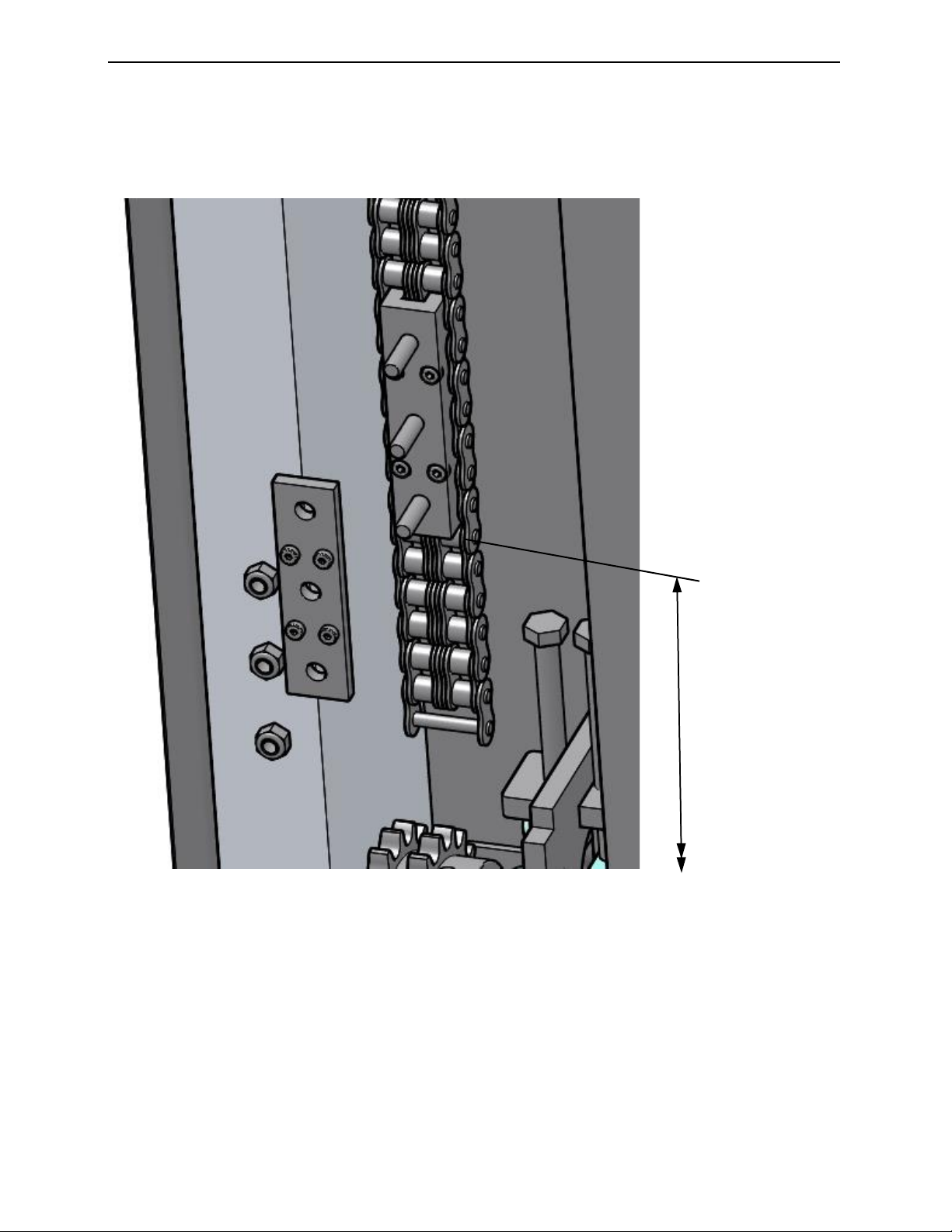
•Locate the Drive Link Connectors in both side columns.
•Remove the three (3) nuts and the Front Connector Plate from each connector (save all items for
Panel Assembly).
•Verify the Drive Link Connectors are 235 mm or 9.25” from the top of the baseplate to bottom of
the connectors. Adjust if needed by moving the chain.
Verify:
235 mm (9.25”) from
top of baseplate to
bottom of connector.
Same dimension on
the Motor side and
the Counterweight
side.

Installation Instructions
JAMISON DOOR COMPANY
8
H4494002 REV B
4. TRANSMISSION SHAFT ASSEMBLY
•Locate the transmission shaft (long round tube with sprocket welded at each end).
•Locate the two short double link chains and the two master chain links.
•Elevate the transmission shaft to the same level as the sprockets near the top of the columns
and spiral plates.
•Assemble the double link chains onto the sprockets on each end of the transmission shaft and
the corresponding sprockets at each end of the column assemblies.
•Assemble the master chain links into the double link chains.

Installation Instructions
JAMISON DOOR COMPANY
9
H4494002 REV B
Master Link
Pins
Master Link
Pins
Clip
Intermediate
Plates
End Plate
End Plate
Intermediate
Plates
Clip
Installation Instructions
JAMISON DOOR COMPANY
10
H4494002 REV B
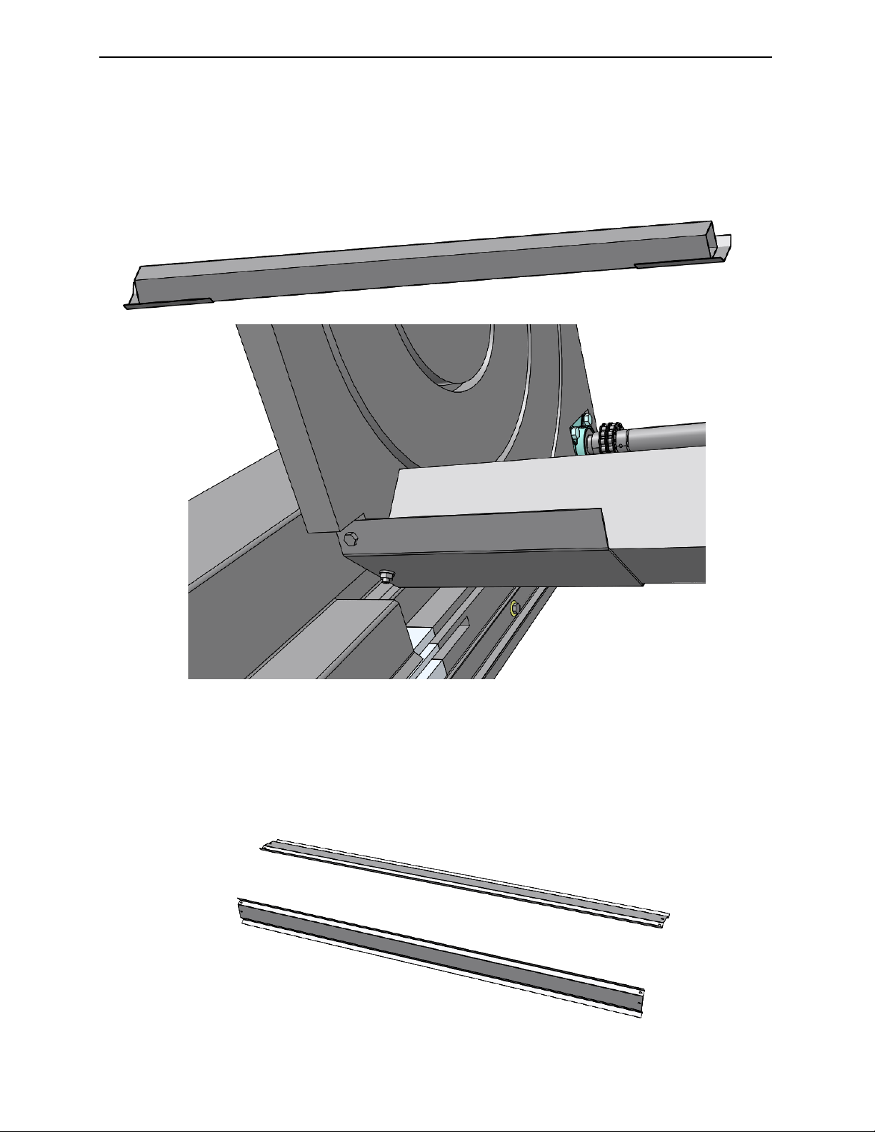
5. LIFTING BAR AND SPACER BAR ASSEMBLY
•Locate the lifting spacer bar (long square tube with welded flange at each ends).
•Remove the preassembled hex nuts from the studs at the bottom on the spiral plates.
•Match and place the color dot on the lifting spacer bar end to the color dot on the spiral plate.
•Assemble lifting spacer bar to the studs at the bottom end of the spiral plates.
•Tighten the hex nuts of the lifting spacer bar and install one lag screw at each flange plate (into
the pre-drilled hole within the spiral plate).
•Locate the two long front spacer bars and assemble them to the spiral plates with lag screws.
Again, match and place the color dot on the spacer bars to the matching dot on the spiral plate.
(The bottom back spacer bar has one less flange compared to the other spacer bars. This
spacer bar will replace the lifting bar after the unit is anchored to the wall and floor.)

Installation Instructions
JAMISON DOOR COMPANY
11
H4494002 REV B
6. MECHANICAL ASSEMBLY
•Remove the front covers from both Column Assemblies. Remove the two flat head bolts, one in
each of the spiral plate, holding the front cover in place.
•Position the lifting apparatus (ex: fork truck) between the Column Assemblies and forks under the
lifting spacer bar.
•Assistance will be required in guiding the legs while it is being lifted to prevent damage to the
unit.
•Remove any fasteners on the back side of the column holding the counterweight shipping block.
•Position the unit in the center of the opening.
•Check unit to be level between Column Assemblies. Shim Column Assembly if needed.

Installation Instructions
JAMISON DOOR COMPANY
12
H4494002 REV B
•Measure between the black tracks at four (4) different elevations. The distance must be the
same at all four elevations.
A=B=C=D
•Install fasteners into the mounting slots within the Column Assemblies, slots near the motor
bracket, slots near the counterweight pulley, and the angle brackets by the transmission tube
unions.
•Verify distance between tracks did not change. Install floor anchors.
•Remove the lifting spacer bar from the back of the bearing plates and install the last spacer bar
(match color dots).
•If center bearing was provided, assemble to center of transmission shaft assembly and the wall.
A
B
C
D
NOTE: Replace lifting
spacer bar with spacer
bar after the columns
are anchored in place.
Assemble the center bearing assembly (if
provided) to the center of the transmission
shaft assembly and the wall.
Installation Instructions
JAMISON DOOR COMPANY
13
H4494002 REV B
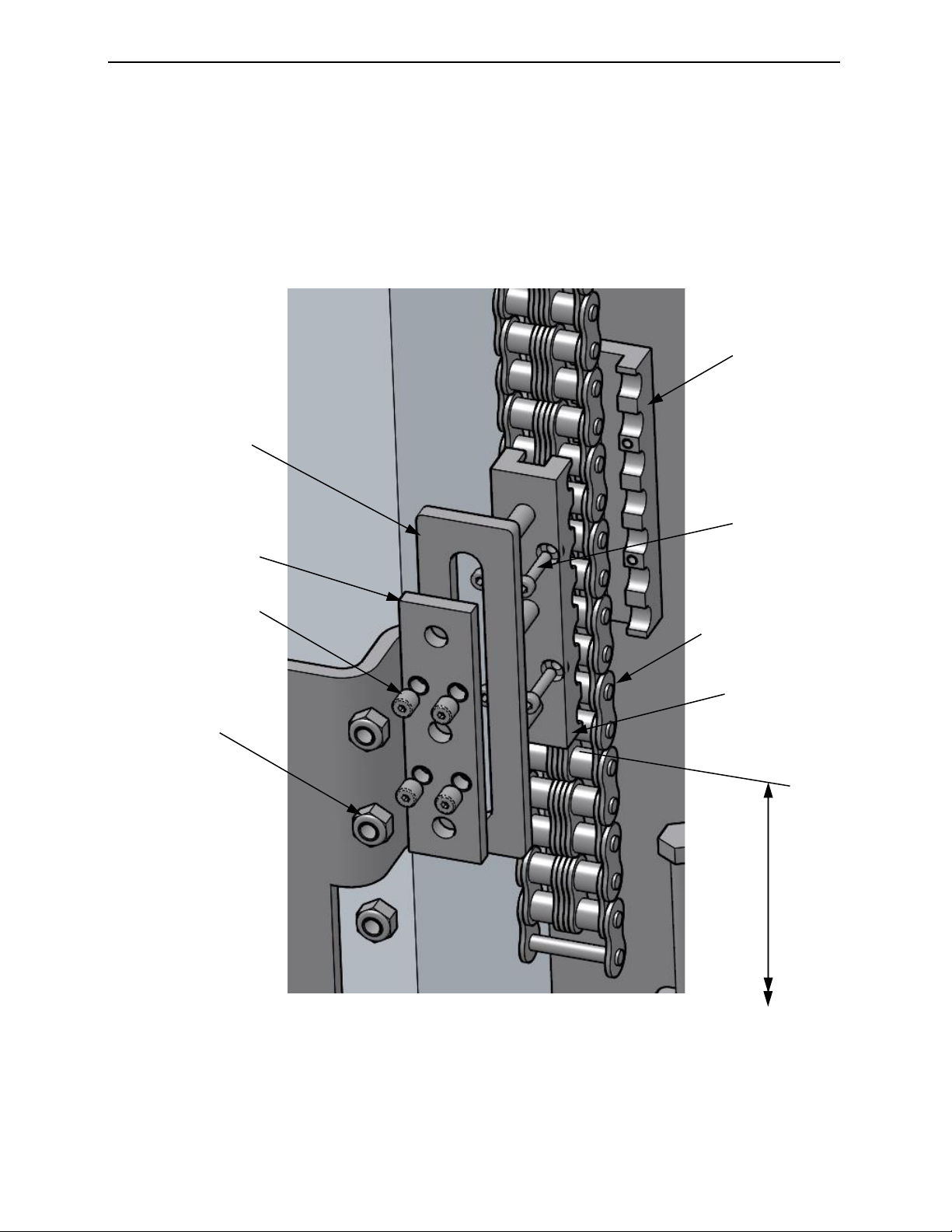
7. PANEL ASSEMBLY
•Locate the drive link connectors in both side columns.
•Locate the three (3) nuts and the front connector plate from each connector.
•Install panel #1 (panel with gasket at the bottom) into the opening. The three studs of the drive
link connectors must go through the slots of the drive links.
•Loosely assemble the front connector plates and the hex nuts onto the connectors.
•Insert two pins per side with the rounded end into the track (and install set screws).
•Measure to ensure the panel is level. Tighten the hex nuts and the four (4) headless screws
within the front connector plates against the drive link.
Drive Link
Front Connector
Plate
Headless
Screw
Nut
Connector,
Front Half
Chain
Screw
Connector,
Back Half
Verify:
235 mm (9.25”) from
top of baseplate to
bottom of connector.
Same dimension on
the Motor side and
the Counterweight
side.

Installation Instructions
JAMISON DOOR COMPANY
14
H4494002 REV B
Pin
Set
Screw
Pin
Set
Screw

Installation Instructions
JAMISON DOOR COMPANY
15
H4494002 REV B
•Adjust the drive link spacers to 1-2 mm (on either side) away from the tracks.
•*If any of the drive link spacer screw was removed, add thread locking liquid to the threads of the
screw before reassembling.
•Verify the bottom panel is still level.
•Prepare the panels for installations by removing the protective films. The panels are numbered
for assembly order (the marking is on one end of the panel).
•Prepare for panel assemblies, gathers panels, pins, set screws, and panel end bushings.
•Remove the two top pins from the bottom panel. Stack panel #2 onto panel #1, insert pins
between panel #1 & #2, the flat end of the pin should be even with the hinge.
•Assemble set screws.
•Continue panel stacking, pin insertions, and set screws to close off opening.
•If center hinges are present, insert center pins into center hinges and set screws. (Center pins
have flat ends.)
•Assemble panel end bushings to the top hinge pin on every sixth panel.
Drive Link Spacer
1-2 mm gap (per side)
*Drive Link
Spacer Screw
Installation Instructions
JAMISON DOOR COMPANY
16
H4494002 REV B
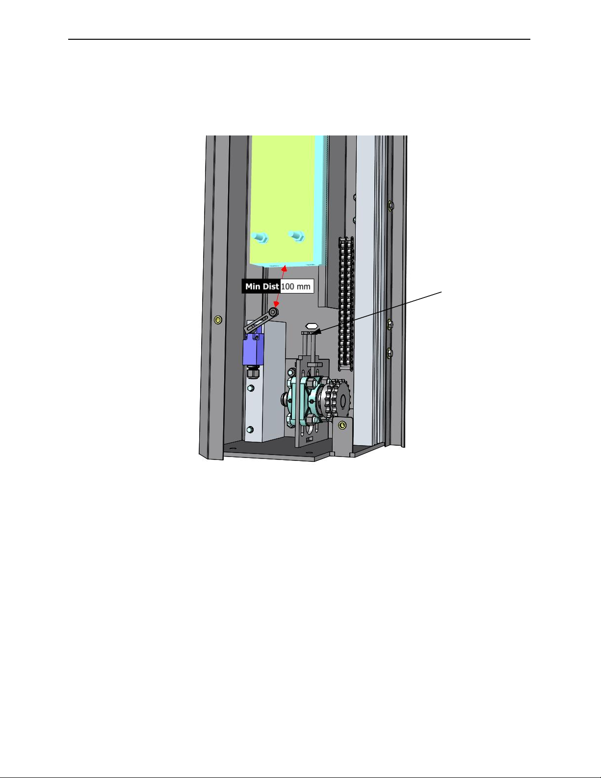
8. COUNTERWEIGHT BELT ASSEMBLY
•With panel assembly complete, install the chain to the chain-fall.
•Activate the manual brake release, rotate brake level from horizontal position to vertical position.
•Manually open (or elevate) the door panel assembly to the operational open position.
•Set the counterweight assembly to approximately 100 mm above the wheel of the safety switch.
Drive Chain
Tension Adjustment
Screws

Installation Instructions
JAMISON DOOR COMPANY
17
H4494002 REV B
•Unroll the counterweight lifting belt. Leave minimum of two (2) wraps of the belt around the shaft.
•The belt must unroll from the front of the pulley (not the back of the pulley) down to the
counterweight.
•Install the belt to the counterweight per the attached example of the belt routing and fastening to
the counterweight assembly.
•The lift belt should pass between the back clamping plate and the back counterweight lift plate.
•The lift belt continues through the counterweight lift plates.
•Turn the lift belt up between the front counterweight lift plate and the front clamping plate.
•Loop lift belt back down between the lifting belt and the front clamping plate.
•Insert the pin through the loop of the lifting belt. Pull lifting belt tight and tighten clamping plates.
•Manually lower the door panel completely and verify the counterweight assembly is at about 200
mm (or more) from the pulley.

Installation Instructions
JAMISON DOOR COMPANY
18
H4494002 REV B
9. CABLE CONNECTIONS
•Locate the light curtain communication cable near the counterweight pulley area.
•Connect the light curtain cable to the corresponding connector on the motor column assembly.
•Locate safety switch wire (2-conductors) near the pulley area. Route the safety switch wire to the
control panel make connections per wiring diagram.
•Mount control panel to a wall approximately 1400 mm (55”) off the ground and 915 mm (36”) from
the side column. All connections on the control panel must be pointing down.
•Verify the manual brake handle is in the horizontal position before programming the limits of the
door panel.
•Install chain-fall activation and deactivation ropes and handles.
•Verify the chain-fall is in the free-wheeling mode before programming the limits of the door panel.
•Have a qualified electrician apply power to the control panel per wiring diagram.
Freewheeling mode
(no indicator showing)
Active mode
(Indicator showing)
Installation Instructions
JAMISON DOOR COMPANY
19
H4494002 REV B
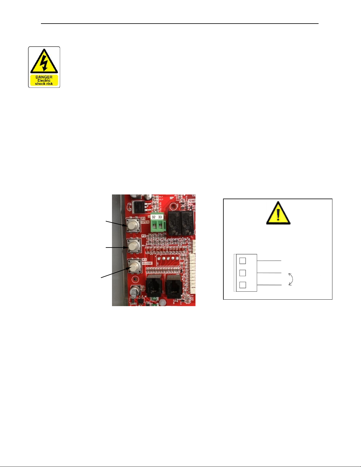
10. MOTOR ROTATION
Jog open button (P1)
Programming button (P2)
Jog close button (P3)
To reverse rotation swap terminals 23
and 24 on the controller board
23
24
25
Any electrical work must be done by qualifed and
knowledgeable personnel, serious injury or death could
result if work is done by unqualifed personnel.
•See wiring diagram for location for landing power and ground.
•Before connecting power to the control panel check the control transformer setting to be sure it is set
for the line voltage you will be using, if it is wrong correct it by moving the wire to the appropraite
voltage. If this is incorrect also check the motor wiring to be sure it is correct, see Section 19.
•Jog the door closed using P3, if the door rotates in the wrong direction correct the motor rotation by
reversing the wires on terminals 23 and 24 at the center-right of the control board.
•Once the motor rotation is corrected, use P3 to jog the door to the fully closed position. The jog
buttons may only move the door a few feet even if they are held so you will likely have to push and
hold them more than once to get the door fully closed.

Installation Instructions
JAMISON DOOR COMPANY
20
H4494002 REV B
11. SET DOOR LIMITS, BRUSHES, AND COVERS
•Set the open and close limit of the door panel, see Section 15.
•Install the horizontal brush holder to the doorway opening (with the brush facing the panel).
•Install the L-shaped brush holder to the backside of the panel just above the brush of the
horizontal brush holder.
•Test function of the door.
•Re-install the front column covers.
Table of contents
Other B.M.P. Door Opening System manuals


Popular Door Opening System manuals by other brands

Record
Record system 20 RED Series user manual

Yale
Yale Power Track Series installation instructions

Record
Record DFA 127 instructions

Assa Abloy
Assa Abloy Besam SW200i US Installation and service manual

Crown
Crown Aut-o-doR 1502-1 GENERAL INSTALLATION, OPERATION, MAINTENANCE, and PARTS MANUAL

Sesamo
Sesamo smart PRO operating instructions


