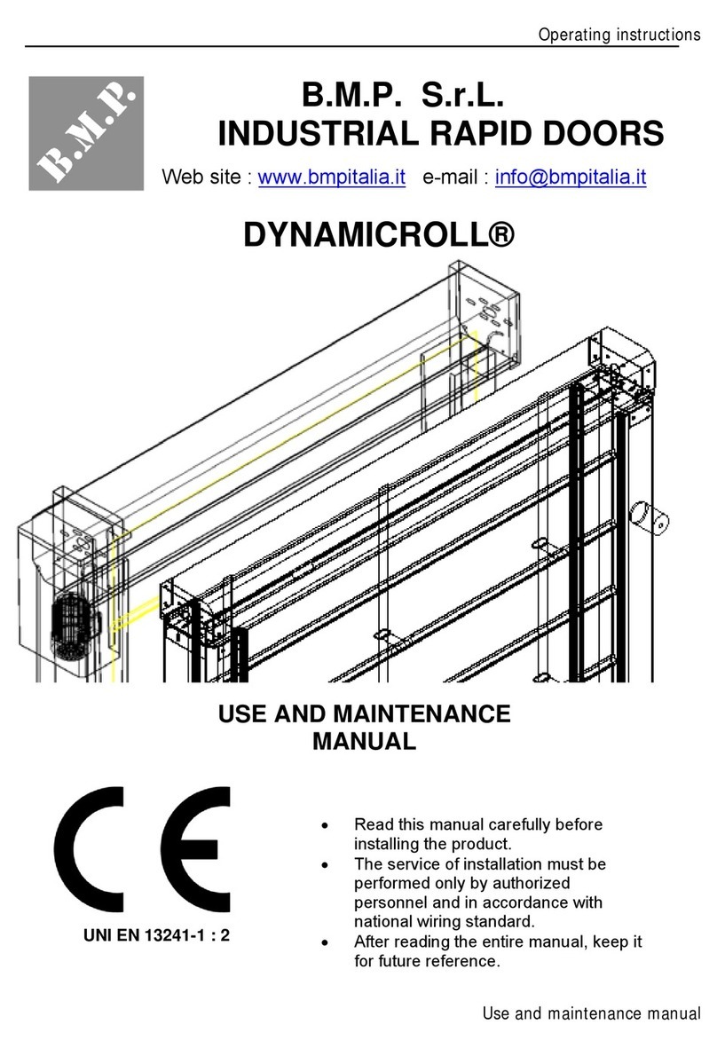
B.M.P. DYNAMICROLL FOOD INOX User manual

Operating instructions
Use and maintenance manual
B.M.P. S.r.L.
INDUSTRIAL RAPID DOORS
USE AND MAINTENANCE
MANUAL
UNI EN 13241-1 : 2
•Readthismanualcarefullybefore
installingtheproduct.
•Theserviceofinstallationmustbe
performedonlybyauthorizedpersonnel
andinaccordancewithnationalwiring
standard.
•Afterreadingtheentiremanual,keepit
forfuturereference.
IMPORTANT
ENGLISH
DYNAMICROLL® FOOD INOX

Operating instructions
Use and maintenance manual
CE DECLARATION OF CONFORMITY
Company
BMP s.r.l.
with head office in
Via Torino, 64/ter
12040 VEZZA D'ALBA (CN)
PRONUNCE
under their responsibility responsabilità that the new:
INDUSTRIAL DOOR
Type
Model
Re
g
ister
Year of construction
Customer
In conformit
y
with directive 89/106/CE with the norm
harmonized EN 13241-1:2003 certified with the system 3
By the institute notified CSI specific - 0497
It i salso in line withthe safet
y
reqiurement specified b
y
machinery derective 98/37/CE with particular reference to the disposition
UNI EN 292/1 e 2 Machine safety. Fundamental concepts, general designed principles
CEI EN 60204-1 Machine safety . Electrical equipment of machines
part 1° : general rules
CEI EN 13241-1:2003
DIRECTIVE EMC 89/336/CE
BMP S.r.L. is the exclusive owner of this document – Reproduction and distribution without written permission is forbidden.

Operating instructions
Use and maintenance manual
WRITE BELOW THE DATA OF THE DOOR (*) :
Type
INDUSTRIAL CLOSURE
Model
DYNAMICROLL®
Register
…………
Yearofconstruction
…………..
(*)Thedatacanbefoundonthelabelonboardthedoororonthedeclarationofconformity
Thismaintenanceregistercontainstechnicalreferenceandrecordsinstallation,routinemaintenance,repairs
andmodification,anditmustmadeavailableforinspectionbyauthorizedperson.
ASSISTANCE DESCRIPTION
Tick the box corresponding to the operation performed. Describe any risk and incorrect use
Installation Maintenance Repair Changes
__________________________________________________
__________________________________________________
__________________________________________________
__________________________________________________
__________________________________________________
__________________________________________________
__________________________________________________
DATE
TECHNICAL SIGNATURE CUSTOMER SIGNATURE
REGISTER FOR MAINTENANCE AND OPERATION
DATA REMENBER

Operating instructions
Use and maintenance manual
Congratulationtohaveboughtourindustrialdoor.
Thisproductistheresultofstudies,researchandlongexperience.Ithadrigorouscontroltoassureyouan
excellentperformanceintheyears.
Readcarefullythismanualbeforeusingthedoor.Inthiswayyoucanuseitcorrectlyandsafely.Inthemanual
therearethemaindataandthenecessaryinstructiontotheuseandmaintenance.
Intheproblemsolvingtableyoucanfindalotofsolutionstocommonproblems;sooftenisnotnecessaryto
callcustomerservice.
Allworkerthatusethedoorandmaintenancepersonnelhavetoreadcarefullythismanual.
WARNING
-Contacttheauthorizedservicetomakemaintenanceorrepairthedoor.
-Contacttheinstallertoinstallthedoor.
-Childrenordisabledcannotusethedooralone.
-Onlyauthorizedpersonnelcaninstallthedoorandinaccordancewithnationalwiringstandard.
TermsanddefinitionsofEN1070,EN12433‐1edEN12433‐2.
Professionalinstaller:personorcompetentorganizationthatoffersinstallationincludingimprovement.
Competentperson:suitablyeducatedpersonthatcancorrectlyinstallandmaintainthedoor.
Register:bookthatcontainsgeneraldatarelatedtoaspecificdoorandhaveanadequatespacewhereregister
theresultofinspection,testing,maintenanceandanyrepairormodificationtothedoor.
Improvementcomponents:componentssuchasmotors,controlunits,securitydevice,installedonanexinting
doortoimprovemotorizedoperation.
Owner:naturalorlegalpersonthathasthedoorandthatisresponsibleforitsoperationanduse.
Maintenance:alloperation(check,lubrification,cleaning,ecc.)sufficienttoensurecorrectandsafeoperation
ofthedooranditscomponentafterinstallation.Maintenanceincludesadjustements,repairorreplacementfor
usuryoraccidentaldistruction,ofcomponentsnotfoundamentalforthedoor.
Maintenanceoperationarenot:
‐replacementofmajorcomponentalthoughtwithidenticalcomponent;
‐replacement/modernizationoftheproduct.
Preventivemaintenance:allmeasuresnecessarytoensuresafeandcorrectoperationofthedoor.
Failure:itislimitatedorimpossibleusingthedoor.
Thepurposeofthismanualistoprovideadequateinformationtotheowner,thecompanythatmaintainsand
anyotherqualifiedandauthorizedpersonnel,regardingtheuseandmaintenanceofthedoor,beingcarefulto
thepossiblerisksrelatedtotheirfailure.
Thismanualinformsonitsuseandbasicmaintenanceandprovideindicationintheeventoffailureor
emergencysituations.
Itdefinestheoperationforcorrectmaintenanceinaccordancewithallsafetyrules.
Anyotheroperation(adjustment,maintenance,repairs)onthedoormustbeperformedbyqualifiedperson.
Thedoorisinstalledinaccordancewiththerulesofgoodpractice.
Installationisinaccordancewiththeinstallationinstruction
Afterinstallationhavebeensuccessfullypassedallthetestsofthecomponentofthedoor
The door can be used only if it has been affixed the CE marking with CE Declaration of Conformity
PURPOSE
TERMS AND DEFINITIONS
INTRODUCTION

Operating instructions
Use and maintenance manual
drawupandsignedbytheproducer
Thedoorcanbedangerousordonotworkcorrectlyifyoudonotrespecttherulesinthismanual.
Thewarrantywillbevoidifnotauthorizedpersondisassembleormodifythedoor.
Producerandinstallerarenotresponsibleforanydamagecausedbyfailuretocomplyoftherulesinthis
manual.
BMPs.r.l.disclaimsanyresponsibilityfordamagecausedbyadoordisassembledormodifiedbynotauthorized
personoradooruseddifferentpurposesthanthoseforwhichitwasdesigned.
Maintenancemustbeperformedbyaspecializedmaintenancecompanyasspecifiedbyinstaller.
Anymodificationandreplacementofpartsmustberecorderintheappropriatesectionofthismanual.
Onlyoriginalsparepartscanprovidefullsecurityandfunctionality.
Theindustrialdoorsaredesignedandmanufacturedtobeinstalledinbothexternalandinternalindustrial
access.
Theusemustbeforalimitednumberofauthorizedperson.
Besidethedoorusedforvehicle,whenthepassageofpedestrianisnotsafe,theremustbepedestriandoors.
Theindustrialdoorsmustbeusedrespectingsafetyrules.
Topreventinjury,followtheinstructionbelow.
Incorrectuse,causedbyfailuretofollowinstruction,cancausedamageorinjury
Pleasenotethatthestickeronthedoorsareapartofthismanualandshowwarningsandsafetymassageand
shouldnotberemovedordamaged
Theimportanceissoclassified:
ATTENTION
Thissymbolindicatesthepossibilityofdeathorseriousinjury.
WARNINGS
Thissymbolindicatedthepossibilityofinjuryordamage.
ATTENTION
Donotdisassembleortrytorepairthedoor.
Contactservicecenter.
Thedoormustbegrounded.
Thiswillpreventfireorelectricshock
Keepawayflammableorexplosivematerialsfrom
thedoor.
Otherwiseitcancausefireordamagethedoor.
Donotinstallthedoorinplaceswithariskof
flammablegasleak.
Otherwiseitcancauseanexplosionorfire.
Donotinstallthedooronfaultyinstallation
support.
Otherwiseitcancausedamageorinjury.
Unpackandinstallthedoorcarefully.
Sharpedgescancauseinjury.
Fortheinstallationalwayscontacttheseller,
servicecenterorfollowtheinstruction.
Otherwiseitcancausefire,electicshockorinjury.
Forelectricalconnectionalwayscontacttheseller,
servicecenterorfollowtheinstruction.
Otherwiseitcancausefire,electicshockorinjury.
Alwaysinstallacircuitbreakerandamaster
switch.
Failuretoinstallcancausefireorelectricshock
Incaseofabnormalnoise,odororsmokecoming
fromthedoorturnoffthecircuitbreakerand
disconnectthepower.
Otherwiseitcancausefire,electicshockorinjury.
Donotsteponorplaceobjectsonthedoor.
Otherwiseitcancauseinjuryordamagethedoor.
Donotturnoffthecircuitbreakerordisconnectthe
powerduringoperation.
Otherwiseitcancausefireorelecticshock.
SAFETY INSTRUCTION
INTENDED USE

Operating instructions
Use and maintenance manual
Donotwettheelectricalparts.
.Otherwiseitcancausefire,electicshockor
damagethedoor
Donotallowchildrentoplaywithcontroldevice.
Keeptheremotecontroloutofchildren.
Otherwiseitcancausedamageorinjury
WARNINGS
Donottransportthedooryourselforbyhands.
Otherwiseitcancausedamageorinjury
Turnoffthepowerbeforeworkingonthedoor.
Otherwiseitcancausefireorelecticshock.
Donotputobjectaroundthedoor.
Otherwiseitcancauseinjury
Duringinstallationdonotgetoninstableobject.
Otherwiseitcancausepersonalinjury
USE RISCK PREVENT
MECHANICAL RISCKS
FormNotPresent /
Failuretothemechanical
resistanceDeterminationwindresintanceclass
CrushriskDuringdoorinstallation Istructioninsidethemanual
CutriskDuringdoorinstallation Istructioninsidethemanual
ELETTRICAL RISK
Elettricshockrisk/Elettricaltransmission comply
withtherules
MATERIAL AND PRODUCT RISK
Risktocontactorinhalation of
harmfulfluids,gases,mists,
fumesanddust.
Notpresent/
DangerousposesoreccesstrainNot present /
Thesoundpressurelevelproducedbytheindustrialdoorwasmeasuredandvaluedsimulatingtheoperationof
thedoorinthefactoryanditis<70dB(A).
Thiswasmeasuredrespecttoanoperatorwithcontrolboardonthesideofthedoor.
Thedoornoiselevelchangeswith:
-Conditionofuse(place,disposition,ecc.)
-Statusofefficiency
-Dimensionofthedoor
Incaseofdisposalofthedoortheownermustdifferentiateitspart.
Thiscanbedonebyspecializedcompaniesauthorizedtotransportandrecyclingasrequiredbylocalrules.
WARNING:donotleavethewreckageofthedoorintheenvironment,thisisaseriousdangerfor
environmentandpeople.
DISPOSAL
NOISE
RESIDUAL RISK

Operating instructions
Use and maintenance manual
-DYNAMICROLL WITH SIDE-MOUNTED MOTOR
1 Photocell
2 Cable
3 Control board
4 Column
5 Crossbar
7 Porthole
8 PVC curtain
9 Motor cover
10 Pol
y
zene
g
uides
11 Side plate
12 Ball bearin
g
13 Shaft
14 Roller tube
15 Pulley
16 Toothed belt
17 Limit switch
18 Limit switch support
19
A
dapte
r
20 400 V tree-phase motor
21
A
dapter support
22 Key
23 Drive shaft
24 Edge cogged curtain
DESCRIPTION OF COMPONENT
3
2
1
4
5
7
8
910
11
12
13
14
15
22
16
18
12
11
24
19
21
23
20
17

Operating instructions
Use and maintenance manual
-DYNAMICROLL WITH FRONTAL MOTOR
1 Photocell 11 Side plate 20 Drive shaft
2 Cable 12 Ball bearin
g
21
A
dapte
r
3 Control board 13 Shaft 22 400 V tree.phase moto
r
4 Column 14 Ruler tube 23 Adapter support
5 Crossbar 15 Pulle
y
24 Co
g
wheel
7 porthole 16 Toothed belt 25 Chain link
8 PVC curtain 17 Limit switch 26 Chain
9 Motor cover 18 Limit switch support 27 Key
10 Polyzene guides 19 Shaft key 28 Shaft
11
12
13
14
3
2
1
4
5
7
8
9
10
11
14
15
16
17
18
19
20
21
22
23
24
25
12
26
27 28

Operating instructions
Use and maintenance manual
INSTALLATION INSTRUCTION
-Always use a power circuit specifically dedicated to the door. For wiring follow the
manufacturer's instructions.
-Tighten the screws of the electrical terminals to prevent loosening.
-Make sure the power source has the required capacity.
-Make sure the thickness of the cable conforms to what is stated in the specification of the
power source.
-Never install a differential circuit breaker in wet or damp areas.
EQUIPMENT NEEDED
1 Flexometer 10 Level
2 Suitable lifting equipment (stairs
elevator, ecc.)
11 Set of allen keys (17 mm, 13 mm,
10mm, 8 mm)
3 Screwdriver set 12 Tester
4 Iron drill 13 Hamme
r
5 Hammer drill 14 Cordless screwdrive
r
6 Drill bits (iron and concrete) 15 Grinder
7 Scissors 16 Silicone
g
un
8 Strippin
g
cable 17 Pliers
9 Vices
Elevator Forklift
INSTALLATION

Operating instructions
Use and maintenance manual
-ThecardinstalledisBMP1_HW
-Thecontrolcardispoweredby230Vsingle‐phase50Hz.
WARNING:Thepowerline230Vsingle‐phase50Hz.mustbededicatedonlytothecontrolboard
andmustnothavecurrentoscillation
-Thecontrolboard,throughmicrocontroller,controlstheoperatingcurrentofthemotorandthe
heatsinktemperature,providingtoreportanymalfunction.
-Allimputsareindicatedbyleds
-Allarmmessagesareindicatedbyflashinglightordisplay
WARNINGAccessories:output24Vac/300mAMAX
output12Vdc/100mAMAX
LEGENDA
1
CONTROL CARD 6 MOTOR BRAKE TERMINAL (N°30-31)
+ FLASHING LIGHT (N°29-30)
2
METAL BOARD 7 CONTROL BOARD LOCK
3
MOTOR TERMINAL
(U-V-W) 8 START BUTTON
4
DOOR LOCK 9 EMERGENCY BUTTON
5
GROUNDING TERMINAL
CONTROL BOARD
3
4
5
6
7
8
9
1 2

T
E
CO
E
RMINAL
N°
1
2
3
4
5
6
7
8
9
10
11
12
13
14
15
16
17
18
19
20
21
22
23
24
Termina
N°
23
24
25
26
27
28
29
30
31
NTROL CA
R
Ju
m
+12 10
0
0 Vdc 10
0
Not used
Signal
-
(op
-
(op
Not used
Photocell /a
n
Opening co
m
Not used
Not used
Start openin
g
Pedestrian s
t
Common im
p
Photocell
Common im
p
Stop
Slow down
o
Slow down
c
Opening lim
i
Closing limit
24 Vac pow
e
24 Vac pow
e
Signal
-(op
t
l
Motor ph
a
Motor ph
a
Motor ph
a
Power p
h
Power n
e
Groundi
n
Flashing li
Phase (C
O
Brake
R
D TERMIN
A
m
per inputs
N
C
0
mA max.
0
mA max.
tion in use 2
0
tion in use 4
0
n
tijamming se
m
mand
g
(standard)
/
t
art
p
uts (+12Vdc
)
p
uts (+12Vdc
)
o
pening limit
s
c
losing limit s
w
i
t switch
switch
e
r accessories
e
r accessories
t
ion in use 20.3
C
a
se
a
se
a
se
h
ase
e
utral
n
g terminal
ght 230
V
O
MMON) flashin
120
V
A
L WITH LI
M
N
.C. not use
d
C
ONNECTI
O
0
.300) opened
0
.300) closed
d
nsor N.
C
/
closing optio
)
)
s
witch
w
itch
300mA max.
300mA max.
00) closed doo
r
C
ONNECTI
O
U
V
W
230Vac
230Vac
V
DC
g light
/
brake
V
DC
Ope
r
Use and mai
M
IT SWITC
H
d
O
N
door signal
d
oor signal
C
.
n in use 000
0
N.O.
N.C.
N.C.
N.C.
N.C.
N.C.
N.C.
r
signal
O
N
r
ating instruct
i
ntenance ma
n
H
N.O.
0
08
N.O.
i
ons
n
ual

Opera
t
Use a
n
Ter
m
N
t
ing instructio
n
n
d maintenan
c
C
m
inal
N
°
1 +
2 0
3 N
o
4
5 S
I
6 N
o
7 P
h
8 O
9 N
o
10 N
o
11 S
t
12 P
e
13 C
o
14 P
h
15 C
o
16 S
t
17
e
18
e
19 N
o
20 N
o
21 2
4
22 2
4
23
24 S
I
Termina
N°
23
24
25
26
27
28
29
30
31
n
s
c
e manual
C
ONTROL C
A
Ju
m
12 100m
A
Vdc 100m
A
o
t used
I
GNAL
-
(optio
n
o
t used
h
otocell /antija
m
pening comma
n
o
t used
o
t used
t
art opening (st
a
e
destrian start
o
mmon inputs
(
h
otocell
o
mmon inputs
(
t
op
e
ncoder green
e
ncoder
y
ello
w
o
t used
o
t used
4
Vac power ac
c
4
Vac power ac
c
I
GNAL
-
(optio
n
l
Motor ph
a
Motor ph
a
Motor ph
a
Power p
h
Neutral.
Groundi
n
Flashing li
Phase (C
O
Brake
A
RD TERM
I
m
per inputs
N
A
max. encode
A
max. encode
n
in use 20.300
)
m
ming sensor
n
d
a
ndard) / closi
n
(
+12Vdc)
(
+12Vdc)
cable
w
cable
c
essories 300m
A
c
essories 300m
A
n
in use 20.300
)
C
a
se U
a
se
a
se
h
ase
230Vac
n
g terminal
ght 230
V
O
MMON) flashin
120
V
I
NAL WITH
N
.C. not use
d
CONNECTI
r red cable
r black cable
)
opened door
s
N.C.
n
g option in use
N.
N
A
max.
A
max.
)
closed door si
g
C
ONNECTI
O
V
W
230Vac
V
DC
g light
/
brake
V
DC
ENCODER
d
ON
s
ignal
N.O.
000008 N.O.
N.O.
N.C.
N.C.
C.
N
.C.
g
nal
O
N

Operating instructions
Use and maintenance manual
ThisisaverticaloperationhighspeeddoorwithPVCcurtain.
Withthedoorareprovided:
Openingsystem(N.O.):
−Greenbuttononcontrolboardandagreenbuttonintheoppositesidetothecontrolboard,when
pressedtheyopenthedoor.
Securitysystem(N.C.):
−Emergencyredbuttononthecontrolboarditstopimmediatelythedoorifpressed.
−Photocellto40/50cmfromthefloor,itstopandreversethedoorinclosingifinterrupted.
−Asafetysensornearrollertube,itcontrolscurtainwrappinganditstopthecurtainifduringthe
closurecurtainsupportonanobstacle.
CONTROL CARD OPERATION MODE
-AUTOMATIC CLOSING ADJUSTABLE (*)
ThissystemallowtoopenthedoorwithSTARTcommandandadjustmentofpausetimeforautomaticclosing.
Toenablethismodeofoperationpositionthedipswitch1onON
(*)Factory mode operation
-STEP BY STEP
ThissystemallowtoopenthedoorpressingSTARTbutton.
ThedoorclosesafterpressingagainSTARTbutton.
Toenablethismodeofoperationpositiondipswitch1onOFF
WARNING!!!THISLOGICDONOTEXECUTETHEAUTOMATICCLOSING
MANUAL OPERATION
OPERATION

Operating instructions
Use and maintenance manual
SAFETY GENERAL RULES
¾Beforeanyinterventionthemaintenancemanmust:
oDelimittheinterventionareaandaffixtherightsignsinordertosignalthemaintenance
worksonthedoor
oControlthattheelectricitypowerisdisconnectedbeforestartthemaintenance
oControltobecorrectelyinformedaboutthemaintenanceandreadandunderstandthis
manual
¾Themaintenancemancan’tusetheelectricalfittingswithoutadeclarationofhisproved
experience.
¾Don’tallownotauthorizedpeopletorepairormaintenancethedoors.
¾Readthemanualbeforemaintainthedoors.
¾Duringmaintenancedon’tuseheatsourcesthatcouldstartfires.
¾Duringmaintenancedonotsolder.
¾Employmentofcompressairisforbidden.
¾Employmentofanysolventisforbidden.
¾Thepresenceofthemaintenancestaffaroundthedoormustbelimited.
¾Thepresenceofotherpeoplearoundthedoorisnecessaryonlytosupportthemaintenancestaff.
ORDINARTY CLEANING AND MAINTENANCE
Theordinarymaintenanceoperationsarealltheoperationsthatcoulddotheuser.
Themaintenanceandclearingofthedoorarenecessarytoobtainthebestfunctioning,highersafetyforthe
userandalongeroperativenessofthedoor.
COMPONENT DESCRIPTION PERIODICITY
Structure
Verifythatthestructureiscorrectelyfixedtothewallinorder
toavoidincidents.
Ckeanwithsoftclothwithoutusinganysolvent(eventuallyuse
waterandsoap)
Ifthereisiceonthestructureimmediatelyremoveit
Six‐month
Photocellandradar
Cleanwithsoftclothwithoutusinganysolvent(industyareas
couldbenecessarytocleanmorefrequentlythephotocells:
dustonphotocellscouldcausemalfunctioningofthe
photocells)
Six‐month
OblòCleantheoblowithasoftclth andifnecessarywithwaterand
soap(donotuseanysolventthatcoulddamagetheoblo)Six‐month
Curtain
Controltheconditionofthebeltsandofthecurtain.
Cleantheoblowithasoftclthandifnecessarywithwaterand
soap(donotuseanysolventthatcoulddamnagetheoblo)
Six‐month
PERIODICAL CHECKS AND MAINTENANCE

Operating instructions
Use and maintenance manual
CHECK, PLANNED INSPECTIONS AND MAINTENANCE
Onlythemaintenancestafforauthorizedpeoplecoulddochecks,plannedinspectionsandplanned
maintenance.
Theseoperationsarenecessaryforthevalidityofthewarranty
INTERVENTION
POINT DESCRIPTION PERIODICITY
Structure
-Verifytheconditionofthefixingframes,thecorrect
closureofthewallanchorsandofthepassingbars(if
present)
-Controlthattherearen’tanystructuraldeformationsdue
tocrashes
Six‐month
Electrical
components
-Verifytheelectricalconnectionsinthecontrolboardand
verifythatthereisnowaterin.
-Controltheelectricalconnectionsinthejunctionboxand
controlthatthereisnowaterinit
-Controltheconditionsandfunctioningofthesafety
components(photocells,safetyedgeandemergency
button)
-Controltheconditionsandfunctioningoftheopening
components(openingbuttonsandoptionalifpresent)
-Verifythatalltheelectricalcablesareingoodcondition.
Six‐month
Mechanical
components
-Verifytheconditionofthemotor
-Controltheconditionofthemotorbrake
-Controlthewearandtensionofthedrivecjhainofthe
motoradapter.
-Controltheconditionofthereducer:oilleak,fixingtothe
motor,fixingofthestructure.
-Controltheconditionofthelimitswitch:wearofthe
beltwheel,wearandfixingofthepulley,thecorrect
functioningofthecammeandswitches.
-Contro,lthecorrectclampingoftheboltsforanypartof
thestructure.
-Verifytheaxialityofthewinderroller
-Controltheconditionandgreasingofthebearings.
-Controltheconditionoftheantiwearwashersonthe
columns
-Controltheconditionandregulationoftheguides(on
thedynamicdoors)
Six‐month
Curtain
-Verifytheconditionandwearofthecurtainandin
particolarintheareassubjecttorubbing.
-Controlthattherearen’tanytearonthecurtain.
-Controltheconditionandregulationofthebelts,lower
andupperfixingplatesandofthebelts(fortherapid
packdoors)
-Verifytheconditionofthecurtainbars
-Controlthecorrectpackagingorrollingofthecurtain
-Controlthetensioningofthecurtain,theconditionand
wearofthezips(forthedynamicdoors)
Six‐month

Operating instructions
Use and maintenance manual
PROBLEM SOLUTION
1 THE WARNING LIGHTS IN THE
CONTROL BOARD DO NOT
LIGHT UP
1CHECK POWER SUPPLY ( 230 V )
1CHECK FUSE
2 THE DOOR DOES NOT MOVE
WITH P1 AND P2 BUTTON
2CHECK SETTING MOTOR WITH PROGRAMMER
(SETTING PARAMETERS – MOTOR TYPE ……KW)
2RELEASE STOP BUTTON (LED 6 turned on)
2CHECK MOTOR CONNECTION (triangle 230V three-
phase, star 380 three-phase)
3 YOU CAN NOT COMPLETE THE
SETTING OF THE CARD
3CHECK WITH PROGRAMMER PARAMETER
OPTION IN USE 4300 FOR SINGLE PHOTOCELL
4380 FOR DOUBLE PHOTOCELL
(with encoder)
3RELEASE THE STOP BUTTON (LED 6 turned ON)
3MOVE THE DOOR WITH BUTTON P1 AND P2 OF
40/ 50 CM AND LOCATE IT ON CLOSE POSITION (
this operation is useful to recognize the encoder )
3VERIFY THAT THE LED LD13 (radio safety edge or
sensor in the upper case) IS ON
3IF NOT, MAKE JUMPERS 7 /13 AND CONTROL
THEN THE SECURITY COMPONENTS
3INVERT THE ENCODER CABLE (yellow with green )
3FOR DOORS WITH UPPER PHOTOCELL CONTROL
THAT LD 3 IS OFF WHEN THE DOOR IS CLOSE
4 YOU CAN NOT COMPLETE THE
SETTING OF THE CARD
4CONTROL THAT THE LIMIT SWITCH ARE
CORRECTLY REGUALATED ( if FCC and FCRC
aren’t pressed the card can’t be set)
(with limit switch )
4VERIFY THAT THE LED LD13 (radio safety edge or
sensor in the upper case) IS ON

Operating instructions
Use and maintenance manual
4VERIFY THAT THE LED LD7 (safety photocell ) IS
ON
4RELEASE STOP BUTTON (LED 6 turned on)
5 YOU CAN NOT COMPLETE THE
SETTING OF THE RESISTIVE
EDGE
5VERIFY THAT THE JUMPER ON THE
TRANSMITTER J1 IS TAKEN OFF
5RESET THE OLD CODES (close the jumper "MR"
press the PROG button until you hear a beeps tight
series, then remove the jumper)
5VERIFY WITH THE TESTER THE CHARGE OF THE
TRANSMITTER BATTERIES
5VERIFY IF THE RESISTENCE(8.2 KΩ) FOR THE
CABLES THAT COME OUT FROM THE EDGE
CHANGES IF YOU PRESS THE EDGE if it doesn’t
change control that the resistive band is perfectly flat
for all the length of the black profile or take out the
gum and control the
5VERIFY THE CONNECTIONS OF THE RECEIVER
6 THE PHOTOCELL DOESN’T
WORK ( LD 7 OFF)
6VERIFY THE ALIGNMENT
6VERIFY THE CONNECTION OF THE BLACK
RECEIVER CABLE( brown +12Vdc) (blue 0V dc ) (
black: signal that it arrives to the terminal 14 in the
local plant)
(the door doesn’t close )
6VERIFY THE CONNECTION OF THE
TRANSMITTER GREY CABLE ( brown +12Vdc) (blue
0V dc)
( ATTENTION! If you invert the brown and blue cables
you will damage the sensors)
7 THE ANTI-JAMMING SENSOR
DOESN’T WORK (sensor)
7VERIFY THE CONNECTION ( brown +12Vdc) (blue +
white 0V dc ) ( black: signal that it arrives to the
terminal 7 in the local plant)
(the sensor doesn’t light up)
8 THE ANTI-JAMMING SENSOR 8BRING THE SENSOR CLOSER TO THE CURTAIN

Operating instructions
Use and maintenance manual
DOESN’T WORK (sensor) 8PUT THE SENSOR FRONTALLY TO THE TUBE
A
XIS
(the door closes but the sensor
doesn’t work if I press it)
8CONTROL THE CONNECTIONS ( brown +12Vdc)
(blue 0V dc ) ( black connected to the cable 7 in the
local plant)
9 THE DOOR STOPS AT THE
PHOTOCELL LEVEL AND
COMES BACK
9REGULATE THE SLOWING DOWN LIMIT SWITCH:
IT CLOSES 10 CM BEFORE THE PHOTOCELL ( the
contact switch off the functioning )
10 THE DOOR CLOSES ONLY 50
CM AND THEN COMES BACK
10 INCREASE THE INTERVENTION TIME OF THE
ANTI-JAMMING PHOTOCELL USING THE
PROGRAMMER (PARAMETER SETTING- ANTI-
JAMMING PHOTOCELL READING)
10 LOWER THE ANTI-JAMMING PHOTOCELL
SENSOR
11 LD1 REMAINS ON( IN THE TOP
LEFT-HAND )
11 VERIFIY THE FUSE
11 THE CARD IS DAMNAGED ( replace it)
12 THE DOOR DOESN’T CLOSE
AUTOMATICALLY
12 VERIFY DIP 1 ( ON = automatic ) (OFF = manual )
12 CONTROL THE CORRECT FUNCTIONING OF THE
SAFETY COMPONENTS ( LD 7 - LD 13- LD 6 on)
13 THE DOOR WORKS BUT
SOMETIMES IT GETS STUCK
13 VERIFY THE CORRECT SETTING OF THE MOTOR
WITH THE PROGRAMMER (PARAMETER SETTING
– TYPE OF MOTOR ……KW)
(in any position)
13 CONTROL THAT THE FLASHING LIGHTS WIRES
OR THE MOTOR BRAKE WIRES ARE NOT IN THE
SAME CABLE OF THE PHOTOCELL AND LIMIT

Operating instructions
Use and maintenance manual
SWITCH (interference problem) they must have their
own cable and tube ,the 230V must be separated
from 12- 24V
13 VERIFY WITH THE TESTER THAT THE CURRENT
ISN’T LOWER THAN 220V (control when the door’s
working) if the current is lower than 220V control the
input
13 VERIFY WITH THE PROGRAMMER THAT THE BUS
VOLTAGE ISN’T LOWER THAN 300V (SYSTEM
CONDITION – BUS VOLTAGE) (control when the
door’s working) if the voltage is lower than 300V
control the input.
13 VERIFY WITH THE PRORAMMER THE MOTOR
UPTAKE (SYSTEM CONDITION- MOTOR CURRENT
with motor 0,75kw can’t be higher than 7A;with motor
1,5 kw can’t be higher than 9A, control when the
door’s working) if the door exceeds the threshold
lower the opening HZ
14 THE PHOTOCELL DOESN’T
WORK
14 CONTROL THAT IN THE VICINITY THERE AREN’T
ANY OTHER PHOTOCELLS THAT COULD CAUSE
REFLECTION (try to darken the photocells)
(the door closes but the photocell
doesn’t reverse the curtain)
14 CONTROL THAT WITH THE PHOTOCELL CABLES
THERE AREN’T ANY HIGH VOLTAGE CABLES
(motor ,motor brake, flashing lights, power line) (take
to the control board separated cables in different
pipes, separate the low voltage 12-24V from the high
voltage ≥100V)
14 PUT THE MINUS OF THE RECEIVER (black cable,
blue wire) ground
15 WITHOPENDOOR(locked)THE
CURTAINSLOWDOWN
15 SETTHEMOTORBRAKE(removethefancoverandcloseof
aquarterturnofthedialbrakeadjustement,thenmake
teststoreachtheoptimum)

Operating instructions
Use and maintenance manual
Thedoorisdesignedandmanufacturedtouseasanindustrialclosure.Anydissimilarfromtheoriginalprupose
andthefailuretofollowinstructioncontaininthismanualwillvoidthewarranty.
B.M.P.S.r.L.guaranteethedoorfor12monthsfromthedateofthetestandputinto;thereforeitisessential
tokeepthedocumenttestingwiththismanualandtheinvoiceorreceiptfortaxpurposes.Thewarrantyis
avoidifarenotobservedthetermofpayment.
Thewarrantyissubjecttothereport,withfaxorinthewebsite,whenyoudiscoveranydefects,aftercheck
andadmissionbyB.M.P.S.r.L.
B.M.P.S.r.l.repairorreplaceallpartthatweadmitdefectiveforcauseddependenttothematerialor
workmanship:warrantywillbevoidforthepartdamagedafterinstallationandtestingthedoor,orincorrect
installationormaintenanceiftheyarenotdonebyourstaff,actionbynotauthorizedpersonnel,transport
withoutnecessarycautionandanydamagenotattributabletomanufacturingdefects.
Thewarrantydoesnotcoverpartssubjecttonormalwearandteartoweathering.
Thereplacement,theadditionorthemodification,withoutthepermissionofthemanufacturer,theuseof
componentnotidenticaltothoseprovidedoranyotherbrand,willvoidthewarranty.
TheresponsibilityforB.M.P.S.r.L.remains,however,limitedtotherepairorreplacementofdefectiveparts,
B.M.P.S.r.Ldisclaimanyresponsibilityforanyconsequenceordamagecausedfromgoods,includingworkfor
disassemblyandassemblyoradditionalaccessoriesbought.
Thewarrantyexcludesanyrighttoterminatethecontractofsale,pricereductionandcompensationfor
damage,inadditionreplacingapartdoesnotinvolvetherenewalofthewarrantyperiodontheentiredoor
unlesshasnotreplacedthedoor.
Theusermustobservethesafetywarningsinthemanual,inparticular:
-Operatewithinthelimitofuse
-Alwaysmakeacostantanddiligentmaintenance
B.M.P.S.r.Ldisclaimanyresponsibility,directorindirect,arisingfrom:
-Failuretocomplytheinstructioninthismanual
-Usebyuntrainedpersonnel
-Incorrectinstallation
-Defectinpower
-Notauthorizedchanges
-Notautorizedrepairs
-Seriusmaintenancedeficincies
-Usenotoriginalpartsornotspecificforthemodel
-Exceptionalevents
-Usenotinaccordancewithregulationinthecountryofinstallation
WARRANTY CONDITIONS
Table of contents
Other B.M.P. Door Opening System manuals
Popular Door Opening System manuals by other brands
SDC
SDC EP493 installation instructions
Automatic Technology
Automatic Technology DOMINATOR ShedMaster GDO-8V3 instruction manual
BSW SECURITY
BSW SECURITY 1451 Mounting instruction
Assa Abloy
Assa Abloy Corbin Russwin PED5600 Series installation instructions

Assa Abloy
Assa Abloy DC 700G-FT BGS installation instructions
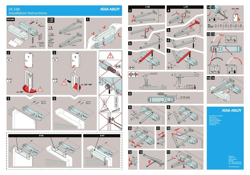
Assa Abloy
Assa Abloy DC340 installation instructions
Nice
Nice AVIO600 Instructions and warnings for installation and use
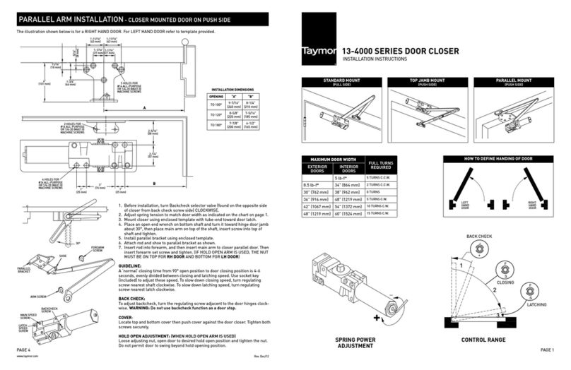
Taymor
Taymor 13-4000 SERIES installation instructions

Dictator
Dictator DICTAMAT 650 quick start guide
Yakima
Yakima AWNING BRACKET KIT Quick start quide
Dormakaba
Dormakaba 8600 EMF installation instructions
Assa Abloy
Assa Abloy SW200 owner's manual
