manuals.online logo
Brands
  1. Home
  2. •
  3. Brands
  4. •
  5. Assa Abloy
  6. •
  7. Door Opening System
  8. •
  9. Assa Abloy Norton 7700ST User manual

Assa Abloy Norton 7700ST User manual

Copyright © 1991, 2014 Yale Security Inc., an ASSA ABLOY Group company. All rights reserved. Reproduction in whole or in part without the express written permission of Yale Security Inc. is prohibited. 80-9377-0510-020 (05-14)
ASSA ABLOY
1Installation InstructionsSlide Track Door ClosersAn incorrectly installed or improperly adjusted door closer can cause property damage or personal injury. These instructions should be followed to avoid the possibility of misapplication or misadjustment.CAUTIONNOTE: For special applications a separate door and frame preparation template is packed with these instructions. Use this instruction sheet for installation sequence and closer adjustments only.• For closers with or without Delayed Action closing feature suffix "DA"• Use of an auxiliary door stop is always recommended. Right Hand Door – RHLeft Hand Reverse – LHRLH – Left Hand DoorRHR – Right Hand ReverseLeft Hand Door – LHRight Hand Reverse – RHRPullSidePushSideComponents:Stop (Push) SideSlide TrackHinge (Pull) SideSlide TrackRH – Right Hand DoorLHR – Left Hand Reverse
Hinge Edgeof Door
Hinge Edgeof Door
Arm Assembly9/64"Hex DriveSocket HeadScrewCoverwith Insert 2 Cover Screws* These units are not permitted to be installed in fire door assemblies.Closer AssemblyPower Adjustment Nut
Standard Closer (4 Valves)
DA Option Closer (5 Valves)
TubeNon Hold Open Models7700ST - 7500STPS7700ST - PS7500STHold Open Models*7700ST-H - 7500ST-HPS7700ST-H - PS7500ST-H
ASSA ABLOY
Copyright © 1991, 2014 Yale Security Inc., an ASSA ABLOY Group company. All rights reserved. Reproduction in whole or in part without the express written permission of Yale Security Inc. is prohibited. 80-9377-0510-020 (05-14)
ASSA ABLOY
2DO NOT use a power drill or driver to turn adjustment nut. This will damagecloser and void warranty.• IMPORTANT: From centerline of pivot point to end of track is 26-1/2" (673mm)• Right hand door shown• Do not scale drawing• Dimensions are given in inches (mm)• Min. ceiling clearance for unit is 2" (50mm) from frame rabbet 110° Max. – Non Hold Open with Spring Buffer 180° Max. – Non Hold Open without Spring Buffer 110° Max. – Hold Open1. Use template to locate holes on door and frame: 4 on door for closer or drop plate. 3 on frame face for track assembly.2. Prepare door and frame for fasteners using chart on this page.FOR 7500 SERIES MODELS ONLY set closer power for door size using chart below:5. Adjust arm to shortest length and install 9/64" hex drive socket head screw from screw pack.6. Place slide arm on pinion shaft using Arm Indexing instructions above.7. Secure arm with arm washer and arm screw.8. Insert arm stud into slide block in track assembly. Secure by pushing in on the retainer clip that extends from the slide block in the track, until it is flush with the slide block.9. Adjust closer. (See Page 4) 9/32" (7 mm);3/8" (9.5 mm) dia. x3/8" (9.5 mm) deep ondoor opposite to closerStandardOptionalThrough-bolts andgrommet-nutsAllPreparation for FastenersDoor or FrameFastenersDrill-Sizes#14 Type "A" SM ScrewWood3/16" (4.30 mm) pilot hole required1/4" - 20 machine screwMetal Drill: #7 (0.201" dia.)Tap: 1/4" - 20 Sex nuts and boltsHollowMetal9/32" (7 mm) through;3/8" (9.5 mm) door faceopposite to closerAluminumor Wood3/8" (9.5 mm) throughInstallation Sequence:Arm IndexingPinion FlatLH DoorRH DoorPinion FlatCloserValvesUpCloserValvesDown3. Fasten closer body to door with power adjustment nut toward lock edge of door and with valves UP for Right Hand door valves DOWN for Left Hand door 4. Fasten slide track to frame face with open side facing down and spring buffer end toward hinge edge of door.1-7/16"(36.5)5-7/8(149)CLHinge or Pivot11(279.4)22(558.8)(3) Holes in Framefor Track11/16(17.5)6-3/4(171.5)Pull Side Application2-3/8(60.3)4"(101.6)4"(101.6)4-3/8(111.1)4"(101.6)(4) Holes in Door for Closeror(4) Holes for 7786 Drop Plate12-3/8(314.3)1-7/16(36.5)3/4(19)Power Adjustment ChartMaximum InteriorDoor SizeMaximum ExteriorDoor Size30 / (.76) 36 / (.91) 42 / (1.07) NOTE: Maximum of 16-1/2 turns(360°) of Power Adjustment Nut. 48 / (1.22)
inches / (meters)
inches / (meters)
Install closer per instructionswith the proper pre-load applied to the arm then adjust spring power. The power adjustment will notwork properly if the closerspring is not pre-loaded.To increase power, use 11/16"wrench to turn poweradjustment nut clockwise.To decrease power, turn nutcounter clockwise. "Spring PowerAdjustment Nut"+
-
502830 / (.76) 36 / (.91) 42 / (1.07) 48 / (1.22) 82511
Copyright © 1991, 2014 Yale Security Inc., an ASSA ABLOY Group company. All rights reserved. Reproduction in whole or in part without the express written permission of Yale Security Inc. is prohibited. 80-9377-0510-020 (05-14)
ASSA ABLOY
31. Use template to locate holes on door and frame: 4 on door for closer or drop plate. 4 on frame soffit for track assembly.2. Prepare door and frame for fasteners using chart on Page 2.FOR PS7500 SERIES MODELS ONLY set closer power for door size using chart below:• IMPORTANT: From centerline of pivot point to end of track is 28" (711mm).• Left hand door shown• Do not scale drawing• Dimensions are given in inches (mm)• Maximum door opening: 100° Max. – Non Hold Open with Buffer in Track 125° Max. – Non Hold Open without Buffer in Track, Auxiliary Door Stop Required 100° Max. – Hold Open Track Installation Sequence:Arm IndexingPinion FlatLH DoorRH DoorPinion FlatCloserValvesUpCloserValvesDown3. Fasten closer body to door with power adjustment nut toward lock edge of door and with valves UP for Right Hand door valves DOWN for Left Hand door 4. Fasten slide track to frame soffit with open side facing down and spring buffer end toward hinge edge of door.5. Adjust arm to shortest length and install 9/64" hex drive socket head screw from screw pack.6. Place slide arm on pinion shaft using Arm Indexing instructions above.7. Secure arm with arm washer and arm screw.8. Insert arm stud into slide block in track assembly. Secure by pushing in on the retainer clip that extends from the slide block in the track, until it is flush with the slide block.9. Adjust closer. (See Page 4)CLHinge or Pivot14(355.6)22(558.8)(4) Holes in Framefor Track1(25)8(203.2)Push Side ApplicationBottom of Frame Stop5-1/2(140)6-3/8(162)2-9/16(65)6-3/4(171.5)2-3/8(60.3)4"(101.6)4-3/4(120.7)4"(101.6)1-5/16(33)5/16(7.9)(4) Holes in Door for Closeror(4) Holes for 7788 Drop Plate12-3/4(323.9)1/4(6.4)DO NOT use a power drill or driver to turn adjustment nut. This will damage closer and void warranty.Install closer per instructionswith the proper pre-load applied to the arm then adjust spring power. The power adjustment will notwork properly if the closerspring is not pre-loaded.To increase power, use 11/16"wrench to turn poweradjustment nut clockwise.To decrease power, turn nutcounter clockwise. "Spring PowerAdjustment Nut"+
-
Power Adjustment ChartMaximum InteriorDoor SizeMaximum ExteriorDoor Size30 / (.76) 36 / (.91) 42 / (1.07) NOTE: Maximum of 16-1/2 turns(360°) of Power Adjustment Nut. 48 / (1.22)
inches / (meters)
inches / (meters)
502830 / (.76) 36 / (.91) 42 / (1.07) 48 / (1.22) 82511
Copyright © 1991, 2014 Yale Security Inc., an ASSA ABLOY Group company. All rights reserved. Reproduction in whole or in part without the express written permission of Yale Security Inc. is prohibited. 80-9377-0510-020 (05-14)
ASSA ABLOY
4Opening Cycle
B
a
c
k
c
h
e
c
k
g
n
i
n
e
p
O
1/8"HexKey
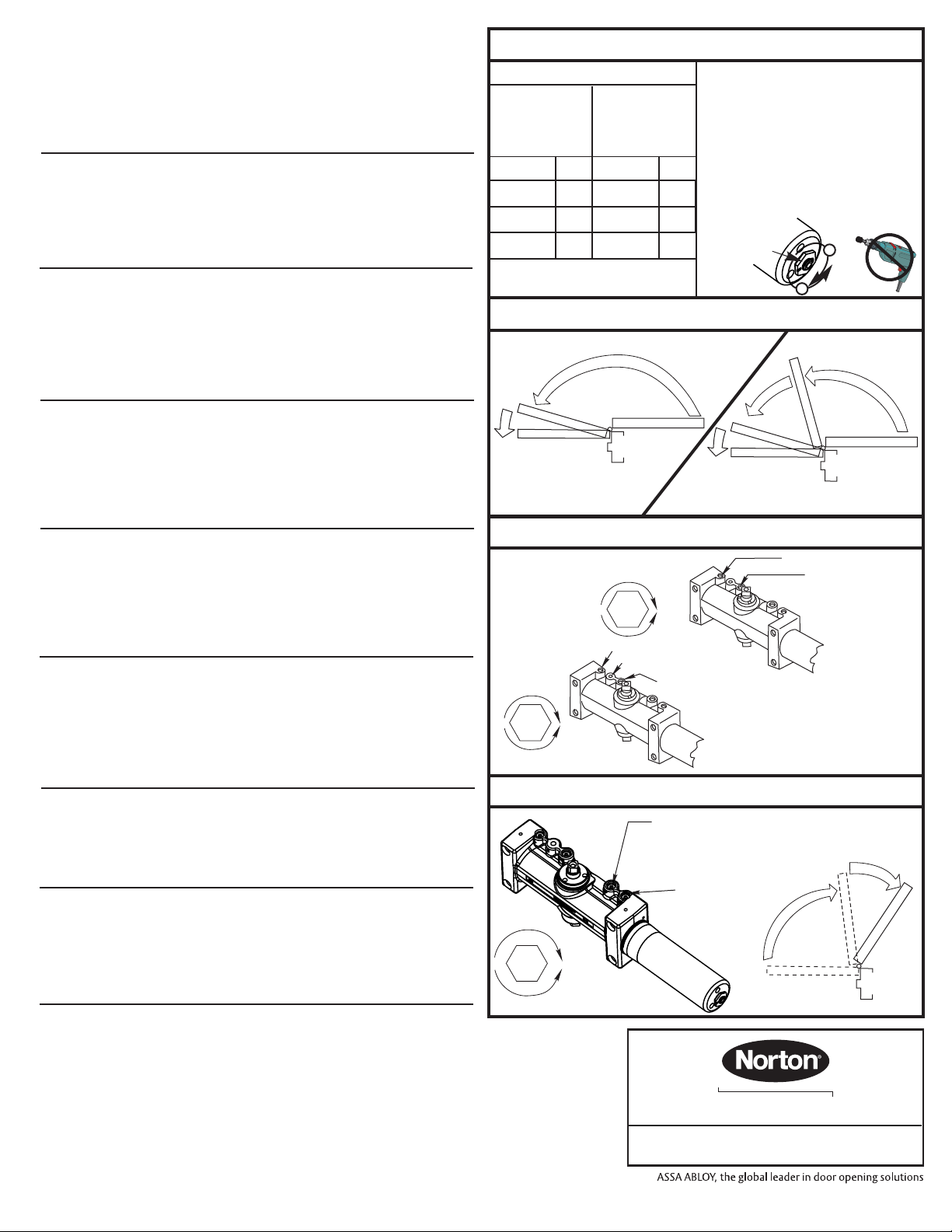
IncreaseDecrease"P" (Normally Closed)Open for backchecklater in door-openingcycle."B"(NEVER CloseCompletely)Opening CycleFigure 4Closing Power ControlFigure 1Adjustment InstructionsArm Attachment to TrackInsert arm stud into slide block in track. Secure by pushing in on the retainer clip that extends from the slide block, until it is flush with the slide block. Door Opening Angle and/or Hold Open Angle:Remove 9/64" hex drive socket head screw from arm. Open door to desired angle and install hex-drive socket head screw into hole in adjusting rod that is aligned with the hole in the adjusting tube.Closing Power7700ST Models come in three different sizes (4 thru 6), each power size can be increase by 50%.7500ST Models are fully adjustable for proper sizing. See chart on page 2 or 3.To adjust closer power - See Figure 1.Closing Cycle (hydraulic control) Standard Closer Only See Figure 2a.Valve "L" controls door speed in Latch range.Valve "S/D" controls door speed in Sweep range.Adjust as shown in Figure 3.Delayed Action Closer OnlySee Figure 2b.Valve "L" controls door speed in Latch range.Valve "S" controls door speed in Sweep range.Valve "S/D" controls door speed in Delay range.Adjust as shown in Figure 3.Opening Cycle (hydraulic control) See Figure 4.Valve "B" cushions (slows) door opening in the backcheck range.Valve "P" allows "backcheck" to begin later in the opening cycle.Adjust as shown in Figure 4.On/Off Hold Open Feature:Slotted screw, accessible thru hole in face of track, engages or disengages the hold open feature with 1/4 turn of the screw. Hold open units are not permitted in fire door assemblies.Hold Open Power Adjustment:If more hold open power is required, the power may be increased by turning the adjustment screw in the end of the track nearest the hinges. Use 9/64" hex wrench provided and rotate adjustment screw clockwise to increase holding power.Installation of Cover:Fasten cover to closer with two screws provided:• Cover fastens at the top of closerClosing CycleFigure 22B2AStandardClosing CycleDelayed ActionClosing CycleClosedClosed
10°
70°
10°
h
c
t
a
L
h
c
t
a
L
R
a
e
p
e
n
w
g
e
S
D
e
l
a
y
R
a
n
g
e
p
e
e
w
S
Closing Speed ControlsFigure 3
1/8"HexKey1/8"HexKey
SlowIncreaseFastDecrease"L" (Latch)"L" (Latch)"S" (Sweep)"S" (Sweep)"D" (Delayed Action)Standard CloserDelayed Action CloserSweep & LatchDelay
3000 Highway 74 East • Monroe, NC 28112Tel: (877)- • Fax: (800)-338-0965974-2255www.nortondoorcontrols.com
ASSA ABLOY
Install closer per instructions with the proper pre-load applied to the arm then adjust spring power. The power adjustment will not work properly if the closer spring is not pre-loaded. To increase power, use 11/16" wrench to turn power adjustment nut clockwise.To decrease power, turn nut counter clockwise.DO NOT use a power drill or driver to turn adjustment nut. This will damage closer and void warranty."Spring PowerAdjustmentNut"+
-
Power Adjustment ChartMaximum InteriorDoor SizeMaximum ExteriorDoor Size30 / (.76) 36 / (.91) 42 / (1.07) NOTE: Maximum of 16-1/2 turns(360°) of Power Adjustment Nut. 48 / (1.22)
inches / (meters)
inches / (meters)
502830 / (.76) 36 / (.91) 42 / (1.07) 48 / (1.22) 82511

This manual suits for next models

5

Other Assa Abloy Door Opening System manuals

Assa Abloy Besam SW300 User manual

Assa Abloy

Assa Abloy Besam SW300 User manual

Assa Abloy Norton 1600 Series User manual

Assa Abloy

Assa Abloy Norton 1600 Series User manual

Assa Abloy RD3 User manual

Assa Abloy

Assa Abloy RD3 User manual

Assa Abloy CloserPlus Ramp Norton XF460 User manual

Assa Abloy

Assa Abloy CloserPlus Ramp Norton XF460 User manual

Assa Abloy Corbin Russwin DC8200 Series User manual

Assa Abloy

Assa Abloy Corbin Russwin DC8200 Series User manual

Assa Abloy DC3210 Series User manual

Assa Abloy

Assa Abloy DC3210 Series User manual

Assa Abloy Corbin Russwin PED5000 DB Series User manual

Assa Abloy

Assa Abloy Corbin Russwin PED5000 DB Series User manual

Assa Abloy SW200 Manual

Assa Abloy

Assa Abloy SW200 Manual

Assa Abloy Sargent 1331 User manual

Assa Abloy

Assa Abloy Sargent 1331 User manual

Assa Abloy RIXSON 185 Quick Spotter User manual

Assa Abloy

Assa Abloy RIXSON 185 Quick Spotter User manual

Assa Abloy Sargent 855 Assembly instructions

Assa Abloy

Assa Abloy Sargent 855 Assembly instructions

Assa Abloy Norton 7540STH Series User manual

Assa Abloy

Assa Abloy Norton 7540STH Series User manual

Assa Abloy MAB 609 + AC593 Instruction Manual

Assa Abloy

Assa Abloy MAB 609 + AC593 Instruction Manual

Assa Abloy Norton 6300 Series User manual

Assa Abloy

Assa Abloy Norton 6300 Series User manual

Assa Abloy SARGENT Powerglide 281 Series User manual

Assa Abloy

Assa Abloy SARGENT Powerglide 281 Series User manual

Assa Abloy Norton PR7500 User manual

Assa Abloy

Assa Abloy Norton PR7500 User manual

Assa Abloy Norton 5700P Series User manual

Assa Abloy

Assa Abloy Norton 5700P Series User manual

Assa Abloy Besam SW200i User manual

Assa Abloy

Assa Abloy Besam SW200i User manual

Assa Abloy Corbin Russwin PED5400 FE User manual

Assa Abloy

Assa Abloy Corbin Russwin PED5400 FE User manual

Assa Abloy SARGENT 2900 FIREGUARD User manual

Assa Abloy

Assa Abloy SARGENT 2900 FIREGUARD User manual

Assa Abloy Norton 7540ST Series User manual

Assa Abloy

Assa Abloy Norton 7540ST Series User manual

Assa Abloy Norton 9540 Series User manual

Assa Abloy

Assa Abloy Norton 9540 Series User manual

Assa Abloy Norton 6000 Series Installation manual

Assa Abloy

Assa Abloy Norton 6000 Series Installation manual

Assa Abloy Adams Rite EX89 Operating instructions

Assa Abloy

Assa Abloy Adams Rite EX89 Operating instructions

Popular Door Opening System manuals by other brands

Yale Delayed Egress 7100 Series installation instructions

Yale

Yale Delayed Egress 7100 Series installation instructions

Beninca KMB24 manual

Beninca

Beninca KMB24 manual

Micom SW800 Operation & installation manual

Micom

Micom SW800 Operation & installation manual

Allegion Briton 3934 Fixing instructions

Allegion

Allegion Briton 3934 Fixing instructions

DITEC COM E installation manual

DITEC

DITEC COM E installation manual

Bohle BO 5215496 instruction manual

Bohle

Bohle BO 5215496 instruction manual

Dormakaba TS93 Series installation instructions

Dormakaba

Dormakaba TS93 Series installation instructions

Record R62 user manual

Record

Record R62 user manual

CAME 803XA-0390 quick start guide

CAME

CAME 803XA-0390 quick start guide

Versus-Omega PENTA CITY 300 user manual

Versus-Omega

Versus-Omega PENTA CITY 300 user manual

Fireco Freedor SmartSound Fitting and Operating Guide

Fireco

Fireco Freedor SmartSound Fitting and Operating Guide

Viking C-3000 Technical practice

Viking

Viking C-3000 Technical practice

GFA ELEKTROMAT KE 120.30 FU-55,00 installation instructions

GFA

GFA ELEKTROMAT KE 120.30 FU-55,00 installation instructions

DH2 Solutions Abloy DA460 Information

DH2 Solutions

DH2 Solutions Abloy DA460 Information

TPG Axim PR-7085P Series manual

TPG

TPG Axim PR-7085P Series manual

GEZE Powerdrive PL-HT installation instructions

GEZE

GEZE Powerdrive PL-HT installation instructions

HOMEBUILDERS HARDWARE LAWRENCE HARDWEAR 8016 Series Installation instruction

HOMEBUILDERS HARDWARE

HOMEBUILDERS HARDWARE LAWRENCE HARDWEAR 8016 Series Installation instruction

CAME PB2100 manual

CAME

CAME PB2100 manual

manuals.online logo
manuals.online logoBrands
  • About & Mission
  • Contact us
  • Privacy Policy
  • Terms and Conditions

Copyright 2025 Manuals.Online. All Rights Reserved.