B meters RFM-LR1 User manual

1User Manual v1.1RFM-LR1
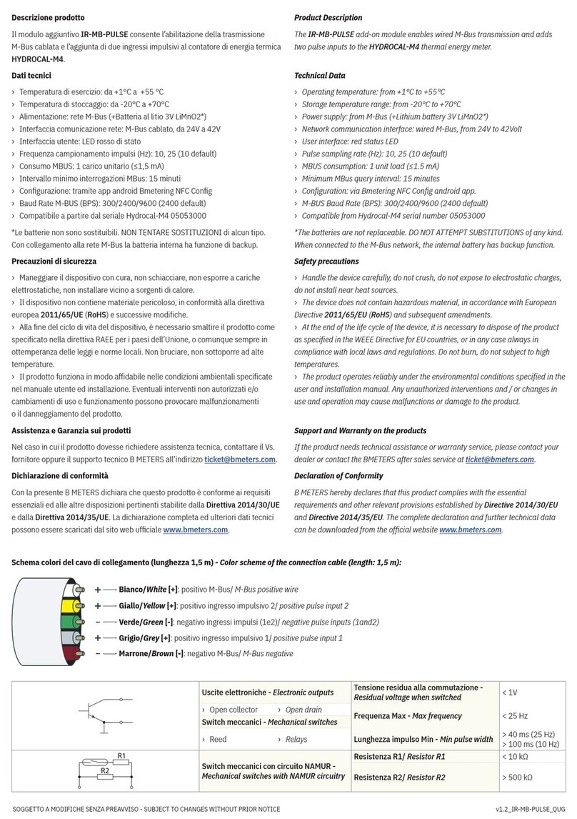
This manual offers a simple guide for getting started with the meter, as well as conguration and information
for advanced users. The RFM-LR1 Water meter module is designed with focus on ease-of-use and reliable
operation in LoRaWAN networks.
The unit is shipped in sleep mode, i.e. with all functions, including radio, deactivated. The device activates when
the red button is pressed for more than 8 seconds. This happens automatically when the unit is mounted on to
a GSD8-RFM mechanical water meter.
The following safety precautions must be observed during all phases of the operation, usage, service or repair
of this product.
• Read the product manual.
• Do not modify the product.
• The product should not be exposed to extreme heat or open ame.
• The device must not be exposed to harsh chemical agents or solvents.
RFM-LR1 manual
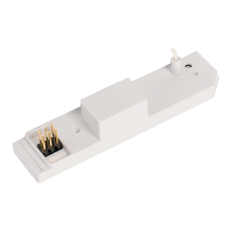
LORAWAN module for GSD8-RFM water meter

RFM-LR1 2User Manual v1.1
The labelling of the product may not be changed, removed or made unrecognizable.
Sensor states and state check
The sensor has four states: Initial, Joining, Congure and Operational state.
Re-join functionality
The device supervises its connectivity to the network, by monitoring that periodic downlink messages are
received.
The device tries to re-join the network if it has not heard anything from the network for 288 uplinks (~ 36 days).
Startup Sequence
When the device has joined the network, startup transmissions are performed to make it easier to congure
the device using downlink commands. When the startup sequence is completed normal operation is started.
INITIAL
JOINING
CONFIGURE
OPERATIONAL
Press button
for 3 sec
Connected to
LoRaWAN network
Polled network
conguration commands
during 2 min
Remote reset (OTA)
or
Re-join

3User Manual v1.1RFM-LR1
There are at least ve startup transmissions. The Status command (index 0x20) is sent unless a reply to a
downlink is sent. If no replies are sent the Status commands are sent with increasing intervals starting with
15 seconds and ending with two minutes. This startup sequence should be utilized to set the starting value of
the water meter (if not equal to 0 m3). For accurate calibration, the water meter should not be used during the
calibration.
Physical installation
When the meter has been digitally congured into your Lora network it is time to physically activate and install
it. The installer mounts the RFM-LR1 unit on the GSD8-RFM and mount the locking pin and seal.
Physical installation process
1. Mount RFM-LR1 unit on the water meter
2. Mount the locking pin and seal
Activating on the network
Standard devices are congured to use OTAA (Over The Air Activation). It is possible to order a batch of devices
congured for ABP (Activation By Personalization).
Standard devices are congured with the AppEUI (a.k.a. JoinEUI) 70-B3-D5-D7-2F-F8-1301. It is possible to
order a batch of devices congured with a customer unique AppEUI for this contact B METERS support.
Upon receiving your RFM-LR1 you can request from B METERS the necessary information to connect it to your
network server. This consists of the following:
1. DevEUI
2. AppKey
These codes are unique for each device. The DevEUI can be seen as a unique identication code, the AppKey is
a securely generated authentication code.

RFM-LR1 4User Manual v1.1
The rst step you should take is to simply provision the network server. This can be any LoRa system that you
would like to integrate the sensor with, with the AppEUI.
The second step is to provision the application server with your unique DevEUI and AppKey.
Digital activation process
1. Provision network server with AppEUI
2. Provision application server with unique DevEUI and AppKey
Alarms
The RFM-LR1 LoRa module have several alarm functions built in.
When an alarm is detected the corresponding alarm flag in the status data is set. When any alarm flag is set
the status, data is included in every report. The alarm flag must be reset manually using a Downlink command.
Module removed
If the module is removed from the water meter after activation this alarm flag is set.
Magnetic fraud attempt
The module has a detector that can sense if a magnet is used to manipulate the function of a dry dial water
meter. If a magnet is sensed the alarm flag is set.
Flow exceeds Q3
If the flow exceeds Q3 for more than 10 minutes the alarm flag is set. Q3 depends on the water meter (based
on pipe) and should be congured using a Downlink command. The default Q3 value is based on the largest Q3
for the specic series.
Leak detection
If a continuous flow has been detected for 24 hours the alarm flag is set. Two congurations parameters are
used for this alarm, Leak window size and Leak zero tolerance, and these can be congured using Downlink
commands. The leak window size denes how long it should be between the detected water meter movements
to consider no flow.
Alarm reset
The alarm flags are reset by setting the Status data with a Downlink command. Setting it to 0 resets all alarms.
Setting it to 0xFE resets alarm flag 0.

5User Manual v1.1RFM-LR1
Specication
Versions
RFM-LR1 LoRaWAN Water meter
Operations
Operating temperature 0°C to +55°C
Connectivity
Network LoRaWAN
Frequency bands 868 MHz
Provisioning Over the air & personalization
Security
Algorithms AES-128
Hardware Cryptographic co-processor
Features Secure boot, Secure rmware upgrade
Hardware based ultra-secure key storage
Battery life
Battery life length > 10 years (at 4-hour intervals, at SF12)
Primary cell Lithium-Manganese 3V
Capacity 2.2 Ah
Method
Optical readout Using infrared diodes
Weight
Weight 85 g
Conguration
Transmission intervals 4 hours, congurable over the air
Starting value Congurable over the air
Unique App EUI available upon request
Alarm functions
1. Module removal
2. Flow exceeding threshold value continuously (congurable)
3. Magnetic fraud attempt
4. Leak detection (congurable)
Enclosure
IP68
Certications
RoHS compliant
CE
LoRaWAN

RFM-LR1 6User Manual v1.1
Protocol
The protocol consists of different types of data
- LoRaWAN v.1.0.2 standard commands
- Unsolicited uplink status commands during congure state
- Periodic measurement reports
- Downlink commands and queries
- Uplink query response
Note 0x denotion means hexadecimal encoded.
Unsolicited uplink status commands
The sensor polls the server for conguration parameters the during the Congure state. This is done by sending
unsolicited uplink status report (0x20). This is gives quick feedback to the installer that the installation has
been successful and enables downlink conguration commands to be sent. After approximately 2 minutes the
device changes to Operational state.
Port: Port 1
Payload 0x01 20 00
0x01: Data type
0x20: Status command
0x00: bit0 =0 => Normal startup
bit1 =0 => No boot problem
bit2-7 reserved
The expected behavior is 0x01 20 00.
Downlink commands and queries
This describes the payload data that is sent to and from the application server. All downlink application
communication is done on LoRaWAN port 1.
Uplink command device => network
Field Bytes Value Description Note
Type 1 xx 0x01: Data
0x02: Command NACK
Index 1xx Command Index
Data As dened for Command Index (only for Type: Data)
Downlink command network => device
Field Bytes Value Description Note
Type 1 xx
0x01: Set
0x02: Query
0x03: Action
Index 1xx Command Index
Data
As dened for Command Index only applicable for set-commands

User Manual v1.1
RFM-LR1
Index Description Datatype Encoding Valid range Access Unsolicited Description Note
0x03 FW build hash 6 x Uint8 Query No Unique number that identies the rmware version
0x05 Device reset Action No Reset of device
0x06 CPU voltage Uint8 25mV/
LSB 0 - 3.6V Query No Read CPU voltage.
Max/min ranges depend on battery chemistry.
0x0A CPU temperature Uint16
Big endian
0.01C /
LSB -50 - +125 C Query No Temperature from CPU sensor with 50 °C offset.
Approximately 5 °C accuracy.
0x20 Status Uint8 Biteld Set
Query Yes
Bit 7: Flow exceeds Q3 at least for 10 min
Bit 6: -
Bit 5: Magnetic fraud attempt
Bit 4: -
Bit 3: Module removed
Bit 2: -
Bit 1: -
Bit 0: Leakage during last 24 hours
To clear alarms:
0xFF clears no alarms,
0x00 clears all alarms,
0x80 clears all alarms except
‘module removed’ etc.
0x21 Volume Uint32
Big endian Liter Query Yes Volume as indicated on meter x 0.001 m3
0x22 Reporting interval Uint16
Big endian Minutes 1-10080 Set
Query No Reporting interval in minutes
0x25 Starting value Uint32
Big endian Liter Set
Query No Volume as indicated on meter
x 0.001 m3
0x27 Back flow volume Uint32
Big endian Liter Query No Volume as indicated on meter
x 0.001 m3
0x2B Q3MaxFlow Uint16
Big endian Liters per hour 0 - 65535 Set
Query No Corresponds to mechanical meter Q3 (based on pipe)
0x2C Leak Window size Uint8 Number of 15
seconds samples 1 - 255 Set
Query No
The size, in units of 15 seconds sample windows, in
which we expect flow below “zero tolerance” to reset
leak detection
0x2D
Leak Zero tolerance
UInt8 Opto phase
changes 0 - 255 Set
Query No Zero tolerance, max number of shaft phase changes
considered “not moving”.

9User Manual v1.1RFM-LR1
Examples
Uplink: 012100001738
Normal Volume with the meter reading 5944 liter
Uplink: 012100001738012008
Normal Volume with the meter reading 5944 liter combined with Status data indicating Module removed alarm flag
Downlink: 012000 Uplink: 012000
Resets all alarm flags
Downlink: 012205A0 Uplink: 012205A0
Sets the Reporting interval to 1440 minutes = 24 hours.
Downlink: 0227
Uplink: 012700000017
Query the Back flow volume. The reply is 23 liter.
Reset device
The device can be remotely reset and forced into Joining state. All settings are back to factory default.
Example
Remote device reset: Port 1: 0305

RFM-LR1 User Manual v1.1
CID Command Transmitted by Short Description
0x02 LinkCheckReq End device Used by an end device to validate its connectivity to
a network.
0x02 LinkCheckAns Gateway
Answer to LinkCheckReq command. Contains the
received signal power estimation indicating to the
end device the quality of reception (link margin).
0x03 LinkADRReq Gateway Requests the end device to change data rate,
transmit power, repetition rate or channel.
0x03 LinkADRAns End device Acknowledges the LinkRateReq.
0x04 DutyCycleReq Gateway Sets the maximum aggregated transmit duty cycle
of a device
0x04 DutyCycleAns End device Acknowledges a DutyCycleReq command
0x05 RXParamSetupReq Gateway Sets the reception slots parameters
0x05 RXParamSetupAns End device Acknowledges a RXSetupReq command
0x06 DevStatusReq Gateway Requests the status of the end device
0x06 DevStatusAns End device Returns the status of the end device, namely its
battery level and its demodulation margin
0x07 NewChannelReq Gateway Creates or modies the denition of a radio
channel
0x07 NewChannelAns End device Acknowledges a NewChannelReq command
0x08 RXTimingSetupReq Gateway Sets the timing of the of the reception slots
0x08 RXTimingSetupAns End device Acknowledges RXTimingSetupReq command
LoRa MAC Commands
The RFM-LR1 can be controlled over by sending down link commands.
The following MAC commands per LoRaWAN specication 1.0.2
Contact Info
B METERS srl
Via Friuli, 3 • Gonars 33050 (UD) • ITALY
Tel: +39 0432 931415
Fax: +39 0432 992661
E-Mail (sales/info): [email protected]
E-mail (support): suppor[email protected]
Web: www.bmeters.com
Table of contents
Other B meters Control Unit manuals
B meters
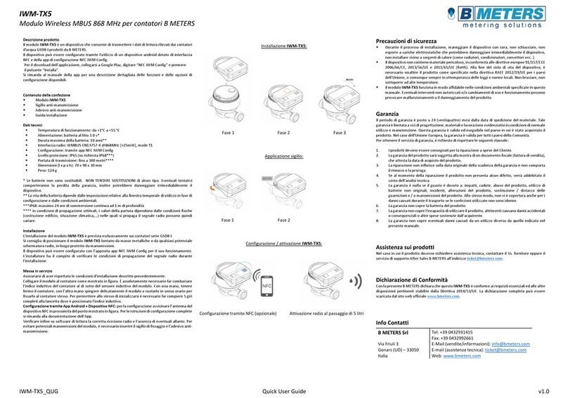
B meters IR-MB-PULSE User manual
B meters
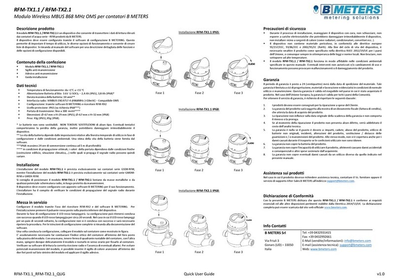
B meters IWM-TX5 User manual
B meters
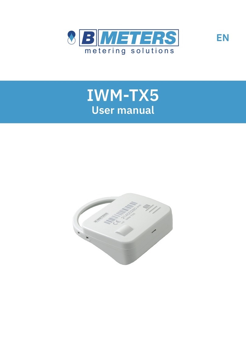
B meters RFM-TX1.1 User manual
B meters
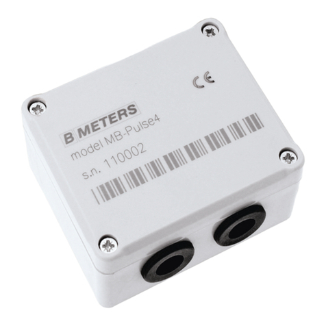
B meters IWM-TX5 User manual
B meters
B meters MB-PULSE4 Instruction manual
B meters
B meters IWM-LR4 User manual

B meters
B meters IWM-LR4 Instruction manual

B meters
B meters IWM-PL3 User manual
B meters
B meters IWM-PL4 Instruction manual

B meters
B meters IWM-MB4 User manual
