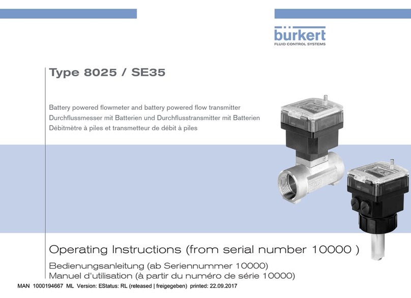
Bürkert 8025 Series User manual

Operating Instructions (from serial number 10000 )
Bedienungsanleitung (ab Seriennummer 10000)
Manuel d‘utilisation (à partir du numéro de série 10000)
Type 8025 / SE35
Battery powered flowmeter and battery powered flow transmitter
Durchflussmesser mit Batterien und Durchflusstransmitter mit Batterien
Débitmètre à piles et transmetteur de débit à piles

We reserve the right to make technical changes without notice.
Technische Änderungen vorbehalten.
Sous réserve de modifications techniques.
© Bürkert SAS, 2013-2017
Operating Instructions 1712/03_EU-ML 00566970 Original_FR

Type 8025 / SE35, battery powered
1. ABOUT THE OPERATING INSTRUCTIONS ......................................5
1.1. Symbols used ......................................................................................5
1.2. Definition of the word "device" ...................................................5
1.3. Validity of the Operating Instructions .....................................6
2. INTENDED USE ..............................................................................................6
3. BASIC SAFETY INFORMATION ..............................................................6
4. GENERAL INFORMATION ..........................................................................8
4.1. Manufacturer's address and international contacts ........8
4.2. Warranty conditions ..........................................................................8
4.3. Information on the Internet ..........................................................8
5. DESCRIPTION .................................................................................................8
5.1. Description of the rating plate ....................................................9
6. TECHNICAL DATA ..........................................................................................9
6.1. Conditions of use ..............................................................................9
6.2. Conformity to standards and directives ................................9
6.2.1. Conformity to the pressure equipment directive ........10
6.2.2. UL certification ....................................................................10
6.3. Material data ....................................................................................... 10
6.4. Dimensions ........................................................................................ 10
6.5. Fluid and electrical data ..............................................................11
7. INSTALLATION ..............................................................................................12
7.1. Safety instructions .........................................................................12
7.2. Installation of flowmeter 8025 ................................................. 13
7.2.1. Install the S020 fitting on the pipe .................................13
7.2.2. Install the flowmeter type 8025 into the S020 fitting 15
7.2.3. Complete the installation ..................................................15
7.3. Installation of the 8035 ................................................................15
7.3.1. Install the S030 sensor-fitting on the pipe ...................15
7.3.2. Install the flow transmitter type SE35 on the
S030 sensor-fitting ............................................................16
7.3.3. Complete the installation of the 8035 ..........................16
7.4. Description of the electronic board connections ..........16
8. ADJUSTMENT, COMMISSIONING ..........................................................17
8.1. Safety instructions .........................................................................17
8.2. Preparing the device for adjustment ................................... 17
8.3. Description of the navigation keys and the
status LED ..........................................................................................18
8.4. Default settings of the device ..................................................19
8.5. Operating levels of the device .................................................19
8.6. Details of the Process level ......................................................21
8.7. Details of the Parameters menu ............................................ 21
3
English

8.7.1. Choosing the display language ......................................22
8.7.2. Choosing the flow rate units, the number of
decimals and the units of the totalizers .........................22
8.7.3. Entering or determining the K factor of the
fitting used ...........................................................................24
8.7.4. Determining the fitting K factor using a Teach-In
procedure .............................................................................25
8.7.5. Configuring the filter ..........................................................28
8.7.6. Resetting both totalizers ...................................................30
8.8. Details of the Test menu ............................................................ 31
8.8.1. Reading the rotational frequency of the paddle
wheel .....................................................................................32
8.8.2. Monitoring the flow rate in the pipe ...............................32
8.8.3. Monitoring the value of the daily totalizer .....................34
8.9. Details of the Information menu ............................................ 34
8.9.1. Reading the capacity of the batteries ...........................35
9. MAINTENANCE AND TROUBLESHOOTING ................................. 35
9.1. Cleaning the device .......................................................................36
9.2. Cleaning the flow sensor for the 8025 ................................36
9.3. Replacing the batteries ............................................................... 36
9.4. If you encounter problems ........................................................37
9.4.1. Resolution of problems when the device status
LED is OFF ..........................................................................37
9.4.2. Resolution of problems when the device status
LED is red and flashing ........................................................ 38
9.4.3. Resolution of problems linked to warning mes-
sages and device status LED is orange and flashing 39
10. SPARE PARTS AND ACCESSORIES .............................................40
10.1. Flow transmitter SE35 ................................................................. 40
10.2. Flowmeter 8025 ............................................................................... 41
11. PACKAGING, TRANSPORT .................................................................41
12. STORAGE .....................................................................................................41
13. DISPOSAL OF THE DEVICE ...............................................................41
4
Type 8025 / SE35, battery powered
English

1. ABOUT THE OPERATING
INSTRUCTIONS
The Operating Instructions describe the entire life cycle of the
device. Please keep the Operating Instructions in a safe place,
accessible to all users and any new owners.
The Operating Instructions contain important safety information.
Failure to comply with these instructions can lead to hazardous
situations. Pay attention in particular to the chapters 3. Basic
safety information and 2. Intended use.
▶Whatever the version of the device, the Operating Instructions
must be read and understood.
▶When the symbol is marked inside or outside the device,
carefully read the Operating Instructions.
1.1. Symbols used
DANGER
Warns against an imminent danger.
▶Failure to observe this warning can result in death or in serious injury.
WARNING
Warns against a potentially dangerous situation.
▶Failure to observe this warning can result in serious injury or even
death.
CAUTION
Warns against a possible risk.
▶Failure to observe this warning can result in substantial or minor injuries.
NOTICE
Warns against material damage.
Advice or important recommendations.
Refers to information contained in the Operating Instruc-
tions or in other documents.
▶Indicates an instruction to be carried out to avoid a danger, a
warning or a possible risk.
→Indicates a procedure to be carried out.
Indicates the result of a specific instruction.
1.2. Definition of the word "device"
The word "device" used in the Operating Instructions refers to the
battery powered flowmeter type 8025 or the battery powered flow
transmitter type SE35.
5
About the Operating Instructions
Type 8025 / SE35, battery powered
English

1.3. Validity of the Operating
Instructions
The Operating Instructions are valid for the battery powered devices
type 8025 / SE35, with a series number equal or higher than 10000.
2. INTENDED USE
Use of the device that does not comply with the instructions
could present risks to people, nearby installations and the
environment.
The flowmeter type 8025, or the flow transmitter type SE35
mounted on a sensor-fitting, is intended to measure the flow rate
of a liquid and to totalize the volume of liquid.
▶Use the device in compliance with the characteristics and
commissioning and use conditions specified in the contractual
documents and in the Operating Instructions.
▶Never use the device for security applications.
▶Protect the device against electromagnetic interference, ultra-
violet rays and, when installed outdoors, the effects of climatic
conditions.
▶Only operate a device in perfect working order.
▶Store, transport, install and operate the device properly.
▶Only use the device as intended.
3. BASIC SAFETY INFORMATION
This safety information does not take into account any contingencies
or occurrences that may arise during installation, use and mainte-
nance of the device.
The operating company is responsible for the respect of the local
safety regulations including for the staff safety.
DANGER
Risk of injury due to high pressure in the installation.
▶Before any intervention on the installation, stop the circulation of
fluid, cut off the pressure and drain the pipe.
Risk of injury due to electrical voltage.
▶Put the power switch to OFF before carrying out work on the
device.
▶Observe all applicable accident protection and safety regula-
tions for electrical equipment.
Risk of burn injury due to high fluid temperatures.
▶Do not touch with bare hands the parts of the device that are in
contact with the fluid.
▶Before opening the pipe, stop the circulation of fluid and drain
the pipe.
Risk of injury due to the nature of the fluid.
▶Respect the prevailing regulations on accident prevention and
safety relating to the use of dangerous fluids.
6
Basic safety information
Type 8025 / SE35, battery powered
English

Various dangerous situations
To avoid injury:
▶Do not use the device in explosive atmospheres.
▶Do not use the device in an environment incompatible with the
materials it is made of.
▶Do not use fluid that is incompatible with the materials the
device is made of.
▶Do not subject the device to mechanical stress.
▶Do not make any modifications to the device.
▶Prevent any unintentional power supply switch-on.
▶Only qualified and skilled staff can carry out the installation and
maintenance work.
▶Guarantee a defined or controlled restarting of the process,
after a power supply interruption.
▶Observe the general technical rules.
WARNING
Risk of burn injury due to the leakage of the chemicals
from the batteries if the batteries are exposed to high
temperatures.
▶Respect the operating temperature of the batteries.
NOTICE
The device may be damaged by the fluid in contact with.
▶Systematically check the chemical compatibility of the com-
ponent materials of the device and the fluids likely to come
into contact with the materials (for example: alcohols, strong
or concentrated acids, aldehydes, alkaline compounds, esters,
aliphatic compounds, ketones, halogenated aromatics or hydro-
carbons, oxidants and chlorinated agents).
NOTICE
Elements / Components sensitive to electrostatic discharges
This device contains electronic components sensitive to electro-
static discharges. They may be damaged if they are touched by an
electrostatically charged person or object. In the worst case sce-
nario, these components are instantly destroyed or go out of order
as soon as they are activated.
▶To minimise or even avoid all damage due to an electrostatic
discharge, take all the precautions described in standard
EN 61340-5-1.
▶Also ensure that you do not touch any of the live electrical
components.
NOTICE
The device may be damaged because the IP65 protection
rating is not guaranteed if the lateral plugs of the flow trans-
mitter are loose.
▶Do not unscrew the lateral plugs.
7
Basic safety information
Type 8025 / SE35, battery powered
English

4. GENERAL INFORMATION
4.1. Manufacturer's address and
international contacts
To contact the manufacturer of the device, use following address:
Bürkert SAS
Rue du Giessen
BP 21
F-67220 TRIEMBACH-AU-VAL
You may also contact your local Bürkert sales office.
The addresses of our international sales offices are available on the
internet at: www.burkert.com
4.2. Warranty conditions
The condition governing the legal warranty is the conforming use of
the device type 8025 or SE35 in observance of the operating condi-
tions specified in these Operating Instructions.
4.3. Information on the Internet
You can find the Operating Instructions and technical data sheets
regarding the type SE35 or 8025 at: www.burkert.com
5. DESCRIPTION
The flowmeter type 8025 is made up of a paddle wheel flow sensor
and a flow transmitter with a display and a cover with lid. The flow-
meter type 8025 must be engaged in a fitting type S020.
The SE35 is a flow transmitter with a display and a cover with lid.
The flow transmitter type SE35 must be mounted on a sensor-fitting.
A flow transmitter type SE35 mounted on a sensor-fitting type S030
is called 8035.
The device is energized by 4 non-rechargeable AA alcaline batteries
of 1.5 V each.
8
General information
Type 8025 / SE35, battery powered
English

5.1. Description of the rating plate
FLOW: 8025 COILLONG SUPPLY: BATT6V...
IP65
S/N 10000
00418405 W44ME
Made in France
2
5
678
34
1
9
10
1. Measured quantity
2. Type of the device
3. Specification of the flow sensor
4. Battery powered
5. Protection rating
6. Manufacturing code
7. Conformity marking
8. Warning: Before using the device, take into account the tech-
nical specifications given in these Operating Instructions
9. Serial number
10. Order code
Fig. 1: Rating plate of the device (example)
6. TECHNICAL DATA
6.1. Conditions of use
Ambient temperature –10...+55 °C (with the delivered
batteries)
When using batteries with a different
brand, the ambient temperature range
can be more restrictive.
Air humidity < 80 %, non condensated
Height above see level max. 2000 m
Protection rating IP65, cover lid and lateral plugs all
screwed tight.
6.2. Conformity to standards and
directives
The applied standards, which verify conformity with the EU direc-
tives, can be found on the EU-type examination certificate and/or the
EU declaration of conformity (if applicable).
9
Technical data
Type 8025 / SE35, battery powered
English

6.2.1. Conformity to the pressure
equipment directive
The device conforms to article 4§1 of the Pressure Equipment
Directive 2014/68/EU under following conditions:
• The flowmeter type 8025 can only be used in the following cases
(depending on the maximum pressure, the DN of the pipe and the
fluid):
Type of fluid Conditions (8025)
Fluid group 1, art. 4 §1.c.i only DN25
Fluid group 2, art. 4 §1.c.i DN≤32
or PNxDN≤1000
Fluid group 1, art. 4 §1.c.ii DN≤25
or PNxDN≤2000
Fluid group 2, art. 4 §1.c.ii
DN≤200
or PN≤10
or PNxDN≤5000
• For the flow transmitter type SE35, refer to the Operating Instruc-
tions of the sensor-fitting used.
6.2.2. UL certification
The devices with variable key PU01 or PU02 are UL-certified
devices and comply also with the following standards:
• UL 61010-1
• CAN/CSA-C22.2 n°61010-1
Identification on the device Certification Variable key
UL-recognized PU01
Measuring
Equipment
EXXXXXX
®
UL-listed PU02
6.3. Material data
Part Material
Housing / seal PC / NBR
Cover with lid / seal PC / silicone
Front foil Polyester
M20x1.5 screw plugs / seal PA / neoprene
Screws Stainless steel
Nut PC
Flow sensor (exposed to the fluid) /
seal (only with 8025) PVDF / FKM
Axis and bearings of the paddle wheel. ceramic
Rating plate Polyester
6.4. Dimensions
→Please refer to the technical data sheet related to the device at:
www.burkert.com
10
Technical data
Type 8025 / SE35, battery powered
English

6.5. Fluid and electrical data
Fluid temperature The fluid temperature may be restricted by
the fluid pressure or by the material of the
fitting used: See Fig. 2 or Fig. 3 and the
Operating Instructions of the fitting used.
The maximal fluid temperature may be
restricted by the maximal operating tem-
perature of the batteries used
Fluid pressure The fluid pressure may be restricted by the
fluid temperature or by the material of the
fitting used: See Fig. 2 or Fig. 3 and the
Operating Instructions of the fitting used.
Flow rate measurement
• Measurement range • 0.3...10 m/s
• Measurement deviation
-with K-factor
determined
with a Teach-In
procedure
-±1 % of the measured value * (at the
value of the Teach-In flow rate)
-with standard
K-factor
-±2.5 % of the measured value *
• Linearity • ±0.5 % of the full scale (10 m/s)
• Repeatability • ±0.4 % of the measured value *
Power supply 4 1.5-V-batteries, connected in series
Minimum charge: 4 years at 20 °C in the
reasonably expected conditions of use
of the device and from the date of manu-
facture of the device.
* Determined in the following reference conditions: fluid = water,
water and ambient temperatures = 20 °C, upstream and down-
stream distances respected, appropriate pipe dimensions.
10
9
8
7
6
5
4
3
2
1
0-15 0 +20 +40+60
PVDF
PVDF (PN10)
PVC (PN10)
PP (PN10)
PVC + PP
11
+80
Utilisation range
P fluid (bar)
T fluid (°C)
Metal
Fig. 2: Fluid temperature - Fluid pressure dependency curves for
the 8025, depending on the material of the fitting S020
11
Technical data
Type 8025 / SE35, battery powered
English

10
9
8
7
6
5
4
3
2
1
0
-30
-10 +10 +30 +50+70 +90
+110
PVDF (PN10)
PVC (PN10)
PP (PN10)
PVC + PP
PVDF
16
15
14
13
12
11
A
Metal
Utilisation range
P fluid (bar)
T fluid (°C)
Fig. 3: Fluid temperature - Fluid pressure dependency curves for
the sensor-fitting S030, depending on the material it is
made of
7. INSTALLATION
7.1. Safety instructions
DANGER
Risk of injury due to high pressure in the installation.
▶Before any intervention on the installation, stop the circulation of
fluid, cut off the pressure and drain the pipe.
Risk of injury due to electrical voltage.
▶Put the power switch to OFF before carrying out work on the
device.
▶Observe all applicable accident protection and safety regula-
tions for electrical equipment.
Risk of burn injury due to high fluid temperatures.
▶Do not touch with bare hands the parts of the device that are in
contact with the fluid.
▶Before opening the pipe, stop the circulation of fluid and drain
the pipe.
Risk of injury due to the nature of the fluid.
▶Respect the prevailing regulations on accident prevention and
safety relating to the use of aggressive fluids.
12
Installation
Type 8025 / SE35, battery powered
English

WARNING
Risk of burn injury due to the leakage of the chemicals
from the batteries if the batteries are exposed to high
temperatures.
▶Respect the operating temperature of the batteries.
WARNING
Risk of injury due to non-conforming installation.
▶The fluid installation can only be carried out by qualified and
skilled staff with the appropriate tools.
▶Respect the assembly instructions for the fitting used.
Risk of injury due to unintentional switch on of power supply
or uncontrolled restarting of the installation.
▶Take appropriate measures to avoid unintentional activation of
the installation.
▶Ensure that the restart of the installation is controlled after any
interventions.
WARNING
Risk of injury if the fluid pressure/temperature dependency is
not respected.
▶Take account of fluid temperature-pressure dependency accord-
ing to the nature of the materials the fitting is made of (see the
technical data and the Operating Instructions of the fitting used).
▶Comply with the Pressure Equipment Directive 2014/68/EU.
Protect this device against electromagnetic interference,
ultraviolet rays and, when installed outdoors, the effects of
the climatic conditions.
7.2. Installation of flowmeter 8025
The flowmeter type 8025 is inserted into an S020 fitting mounted on
the pipe:
1. Install the S020 fitting on the pipe,
2. Install the flowmeter type 8025 into the S020 fitting,
3. Complete the installation.
7.2.1. Install the S020 fitting on the pipe
→Select an S020 fitting suitable for the speed of the fluid in the pipes.
To select a fitting, refer to the calculation tables on the tech-
nical data sheet for the relevant fitting.
→Choose a position for the fitting according to the design of the
pipes, in such a way that:
- the upstream and downstream distances are respected
according to the design of the pipes, see Fig. 4 and norm
EN ISO 5167-1,
- the pipe is always filled in the section around the device (see Fig. 5),
- when the fitting is mounted vertically, the flow direction of the
fluid is upwards (see Fig. 5),
- air bubbles do not form in the pipe in the section around the
device (see Fig. 5).
13
Installation
Type 8025 / SE35, battery powered
English

→If necessary, use a flow conditioner to obtain the best accuracy.
→Install the fitting on the pipe according to the instructions in the
relevant Operating Instructions.
flow direction
50 x DN 5 x DN 40 x DN 5 x DN
25 x DN 5 x DN 20 x DN
5 x DN
18 x DN 5 x DN 15 x DN 5 x DN
With control valve Pipe with 2 elbows at 90° in 3
dimensions
Pipe with 2 elbows at 90° Pipe with 1 elbow at 90° or 1
T-piece
With pipe expansion With pipe reduction
Fig. 4: Upstream and downstream distances depending on the
design of the pipes
Filling of the pipe
in horizontal mounting
Filling of the pipe and fluid flow
circulation in vertical mounting
Correct
Incorrect
Correct Incorrect
shows the fluid flow direction
Air bubbles in the pipe
Correct Incorrect
Correct Incorrect
Fig. 5: Filling of the pipe, flow direction of the fluid, vertical
mounting, air bubbles in the pipe
14
Installation
Type 8025 / SE35, battery powered
English

7.2.2. Install the flowmeter type 8025 into
the S020 fitting
2
1
3
4
5
6
→Install the fitting 5 onto the pipe following
the instructions in chap. 7.2.1.
→Make sure that there is a seal 6 on device 1
and that it is not damaged. Replace the seal
if necessary.
→Insert the nut 3 on the fitting 5.
→Insert the snap ring 2 into the groove 4.
→Make sure that the seal 6 is correctly
inserted on the device 1.
→Insert the device 1 into the fitting.
If the mounting is correct the device cannot be
turned around anymore.
→Hand lock the assembly with nut 3.
Fig. 6: Installation of a flowmeter type 8025 into an S020 fitting
7.2.3. Complete the installation
→Switch the device on (see chap. 8.2).
→Set the K-factor or have it calculated with a Teach-In procedure
(see chap. 8.7.4).
7.3. Installation of the 8035
The 8035 comprises a flow transmitter type SE35 and a sensor-
fitting type S030. The flow transmitter type SE35 is assembled on
the S030 sensor-fitting by a quarter-turn rotation system:
1. Install the S030 sensor-fitting on the pipe,
2. Install the flow transmitter type SE35 on the S030 sensor-fitting,
3. Complete the installation of the 8035.
7.3.1. Install the S030 sensor-fitting on the
pipe
→Select an S030 sensor-fitting suitable for the speed of the fluid
in the pipes.
To select a sensor-fitting, refer to the calculation tables on
the technical data sheet for the relevant sensor-fitting.
→Choose a position for the sensor-fitting according to the design of
the pipes, in such a way that:
- the upstream and downstream distances are respected
according to the design of the pipes, see Fig. 4, page 14,
and norm EN ISO 5167-1,
- the pipe is always filled in the section around the device (see
Fig. 5, page 14),
- when the sensor-fiting is mounted vertically, the flow direction
of the fluid is upwards (see Fig. 5, page 14),
- air bubbles do not form in the pipe in the section around the
device (see Fig. 5, page 14).
15
Installation
Type 8025 / SE35, battery powered
English

→If necessary, use a flow conditioner to obtain the best accuracy,
→Install the sensor-fitting on the pipes according to the instruc-
tions in the relevant Operating Instructions.
7.3.2. Install the flow transmitter type SE35
on the S030 sensor-fitting
1
2
3
→Install the flow transmitter 2 in the
sensor-fitting 1.
→Turn the flow transmitter 2 by a quarter
turn.
→Tighten the lateral screw(s) 3 to lock
the flow transmitter 2 in place on the
sensor-fitting 1.
Fig. 7: Installation of the flow transmitter SE35 on the sensor-
fitting S030
7.3.3. Complete the installation of the
8035
→Switch the device on (see chap. 8.2).
→Set the K-factor or have it calculated with a Teach-In procedure
(see chap. 8.7.4).
7.4. Description of the electronic
board connections
LOCK
ON <> OFF
L+ NC L- FE
P+
P-
Terminal block
Unused connector
Connector of the
flow sensor
Terminal block:
L+: positive power supply (red wire) (factory wired)
L–: negative power supply (black wire) (factory wired)
Fig. 8: Electronic board connections
16
Installation
Type 8025 / SE35, battery powered
English

8. ADJUSTMENT, COMMISSIONING
8.1. Safety instructions
WARNING
Risk of injury due to non-conforming operating.
Non-conforming operating could lead to injuries and damage the
device and its surroundings.
▶The operators in charge of operating must have read and under-
stood the contents of the Operating Instructions.
▶In particular, observe the safety recommendations and intended
use.
▶The device/installation must only be operated by suitably trained
staff.
Danger due to non-conforming commissioning.
Non-conforming commissioning could lead to injuries and damage
the device and its surroundings.
▶Before commissioning, make sure that the staff in charge
have read and fully understood the contents of the Operating
Instructions.
▶Before commissioning the device, adjust the K factor. See
chap. 8.7.3
▶In particular, observe the safety recommendations and intended
use.
▶The device / the installation must only be commissioned by suit-
ably trained staff.
8.2. Preparing the device for
adjustment
ENTER key
locked
LOCK
LOCK
ON <> OFF
L+ NC L- FE
P+
P-
Switch to lock/unlock the
ENTER key
ENTER key
unlocked
LOCK
Switch for the battery
power supply
Fig. 9: Switches on the electronic board
→Loosen the screw and flip the lid.
→Loosen the 4 screws and take off the cover of the housing.
→Put the cover down so that the wires connected to the terminal
block and the wire which connects the flow sensor to the elec-
tronic board are not subject to mechanical stress.
→Make sure that the ENTER key is unlocked. See Fig. 9.
→Put the power supply switch to ON. See Fig. 9.
→Put back the cover and tighten the 4 screws in an alternating
pattern, to make sure that the device is tight.
17
Adjustment, Commissioning
Type 8025 / SE35, battery powered
English

→Adjust the device: see chap. 8.3 to 8.8.
8.3. Description of the navigation
keys and the status LED
• Selecting the displayed
parameter
• Confirming the settings
• Reading the messages
• Scrolling through the
parameters
• Selecting the figure on the
left
• Scrolling up the parameters
• Incrementing the figure
selected
Device status LED: see
Tab. 11.
Fig. 10: Foil of the device
Tab. 11: State of the device indicated by the device status LED
Device status LED Status of the device
OFF The device operates correctly.
Orange, flashing A warning message is generated.
→Press the key for 2 seconds in the
Process level to access the message.
See chap. 9.4.3 for the meaning of the
message.
Red, flashing An error message has been generated.
→Press the key for 2 seconds in the
Process level to access the message.
See chap. 9.4.2 for the meaning of the
message.
Tab. 12: Description of the navigation keys
You want to... Press...
move in the parameters of
a level. • to go to the next parameter.
• 0......9 to go to the previous
parameter.
access the Configuration
level.
ENTER
+ simultaneously for 5 s,
in the Process level
18
Adjustment, Commissioning
Type 8025 / SE35, battery powered
English

You want to... Press...
access the Test menu.
0......9 + +
ENTER
simultaneously
for 5 s, in the Process level
access the Information
menu. for 2 s, in the Process level,
when the device status LED is orange
or red.
reset the daily totalizer.
0......9 + simultaneously for 2 s,
when the daily totalizer is displayed in
the Process level
select the displayed
parameter.
ENTER
confirm the displayed
value.
ENTER
activate the automatic
scrolling of the values dis-
played in the Process level
0......9 for 2 s, in the Process level.
→To stop the automatic scrolling,
press any key.
modify a numerical value.
• 0......9 to increase the blinking digit.
• to select the digit at the left of
the blinking digit.
• 0......9 + to move the decimal point.
8.4. Default settings of the device
Function Default value
LANGUAGE English
UNIT of the flow rate l/min
UNIT of the totalizers litre
Number of decimals Auto
K factor 1
FILTER Filter 2
WARNING-FLOW W– = W+ = 0.000
WARNING-VOLUME 000000
8.5. Operating levels of the device
The device has two operating levels: the Process level and the Con-
figuration level.
The Process level makes it possible:
• to read the flow rate measured by the device and the value of the
totalizers, the main and the daily ones.
• to reset the daily totalizer.
• to access the Configuration level.
The Configuration level makes it possible:
• to set the device parameters.
• to read the rotational frequency of the paddle wheel.
• to read the charge of the batteries.
• to read the error or warning messages generated by the device.
19
Adjustment, Commissioning
Type 8025 / SE35, battery powered
English

LANGUAGE
Process level
Parameters menu Test Menu
UNIT
K-FACTOR
FILTER
TOTAL
END
12.6 L/MIN
87654 L
231 L.
FREQUENC.
WARNING
END
0......9
0......9
0......9
0......9
ENTER
ENTER
SAVE N/Y
> 5 s
> 5 s
Configuration level
0......9
> 2 s
→To reset the daily
totalizer (identified by
a dot after the volume
units).
+
> 2 s
MEAS. OVF
DISP. OVF
Information menu
0......9
Process level
ENTER
END
BATT.
→Activate the auto-
matic scrolling of
the values displayed
in the Process level
0......9
> 2 s
Fig. 13: Diagram of the levels of the device
20
Adjustment, Commissioning
Type 8025 / SE35, battery powered
English
Other manuals for 8025 Series
18
This manual suits for next models
1
Table of contents
Other Bürkert Measuring Instrument manuals

Bürkert
Bürkert 8222 ELEMENT NEUTRINO User manual

Bürkert
Bürkert 8228 ELEMENT User manual

Bürkert
Bürkert 8600 User manual

Bürkert
Bürkert 8025 Series User manual

Bürkert
Bürkert 8012 Series User manual

Bürkert
Bürkert 8202 ELEMENT User manual

Bürkert
Bürkert 8020 User manual

Bürkert
Bürkert LEVEL SWITCH 8110 User manual

Bürkert
Bürkert 8136 User manual