B-Style 43.40.2.300/0 Manual

B-Style |De Geerden 14 |5334 LE Velddriel –NL |www.b-style.eu
Berlingo/Rifter/Combo/
Proace city - L2
LOW FLOOR KIT 43.40.2.300/0
Build Manual
4340I300/2
03-06-2020

4340I300/2
2
Revision Sheet
Revision
Chapter
Page numbers
Date
1
Multiple
Multiple
16-12-2019
2
26 + multiple
Added chapter fixed 2nd seatrow &
changed build sequence
24-06-2020

4340I300/2
3
1. Introduction
This B-style product is a high-quality technical modification to your vehicle. In order to keep up
with technological developments, we are obliged to constantly continue developing our
products. We hope you will understand the need for technical changes and changes in
maintenance operations.
This manual serves as a guide for the lowered floor designed for the Citroën Berlingo, Peugeot
Rifter, Opel Combo and Toyota Proace City.
Kind regards,
B-style
2. General points of attention
•Following the instructions in this manual and adhering to the indicated torque values is
important for good operation of the system and in many cases one of the conditions for
the guarantee.
•If you contact B-style in connection with the conversion, please ensure that you have the
vehicle details and PR number at hand. Without the PR number we are unable to
process any complaints.
•Ensure that the vehicle is on a car lift while working, because work on the underside of
the vehicle is also required. The vehicle must stand or hang flat on the car lift. This is very
important because the body can twist once the floor cut-out has been made.
•For safety-related issues the tightening torque is specified at the corresponding page in
the manual, for general tightening torques see table at the end of the manual.
•Torque tightened bolts must be marked with paint.
•Tighten bolts without locknuts with Loctite 243 or equal thread locking compound.
•Finish untreated edges and holes with etching primer.
•Place covers over the seats.
•Disconnect the battery.
•Don’t grind in the vehicle, always use a saw!!
•After assembling the vehicle, please check the assembly using the checklist in this
manual.
•Use the corrosion protection card to see how to protect the lowered floor kit.
•Please visit the link to fill in the online control form for registration and activating of the
warranty period: https://www.b-style.eu/contact/warranty
•In case of any missing or damaged parts please visit the next link: https://www.b-
style.eu/contact/warranty and fill in the warranty claim form.
•Always refer to the conversion guidelines as mentioned in the bodybuilders
manual of the vehicle manufacturer.
•When using OEM parts/fasteners use the instructions from the vehicle
manufacturer.

4340I300/2
4
3. Table of contents
1. Introduction .................................................................................................................................... 3
2. General points of attention .......................................................................................................... 3
3. Table of contents ........................................................................................................................... 4
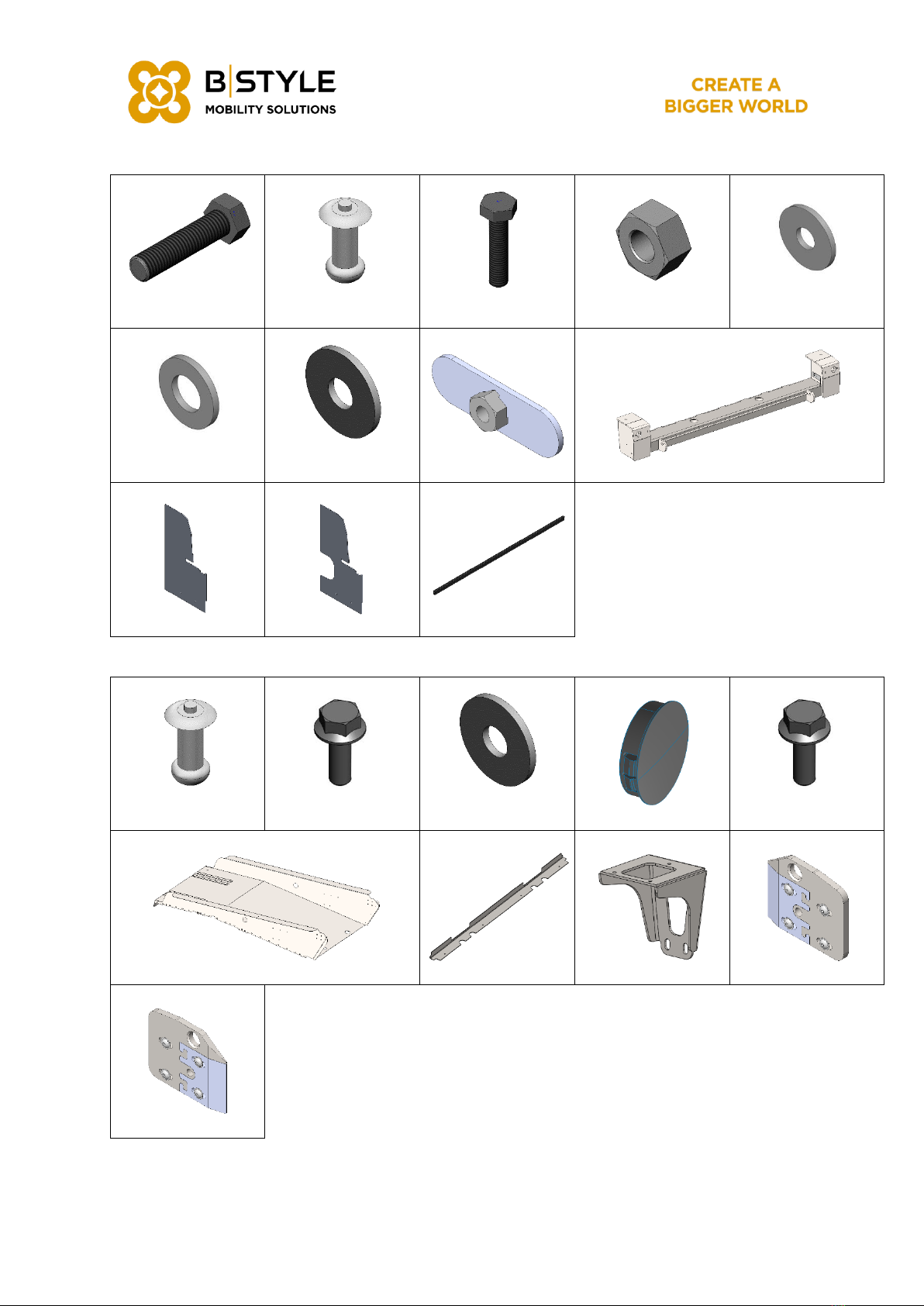
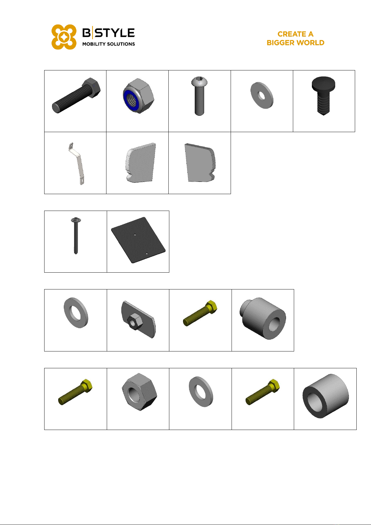
4. Part List............................................................................................................................................. 8
5. Overview....................................................................................................................................... 30
6. Disassembly................................................................................................................................... 32
6.1. Disassembly of the interior....................................................................................................... 32
6.2. Disassembly of the exterior...................................................................................................... 33
6.3. Disassembly of the fuel tank –Diesel ..................................................................................... 34
6.4. Disassembly of the fuel tank –Petrol...................................................................................... 35
6.5. Disconnecting the ‘under body’ wiring loom....................................................................... 36
7. Preparing OEM body ................................................................................................................... 38
7.1. Cutting the floor without template set .................................................................................. 38
7.2. Cutting the floor with template set ........................................................................................ 39
7.3. Drilling holes for wheelchair seatbelt ..................................................................................... 40
7.4. Preparing body for 3rd seatrow consoles............................................................................... 42
7.5. Cutting OEM steel bumper ..................................................................................................... 45
7.6. Cutting OEM bumper without template ............................................................................... 46
7.7. Cutting OEM bumper with template set ............................................................................... 47
7.8. Cleaning underside of body................................................................................................... 48
8. Installing the rear beam (43.40.T.301) ........................................................................................ 50
9. Installing middle frame brackets (43.40.T.201) ......................................................................... 55
10. Installing the shock absorber brackets (43.40.T.202/2) ............................................................ 59
11. Installing the rear low floor (43.41.T.300).................................................................................... 64
11.1. Test fitting the rear low floor .................................................................................................... 65
11.2. Seal and protection instructions............................................................................................. 68
11.3. Installing the rear low floor ...................................................................................................... 70
12. Assemble rear bumper covers (43.54.T.301) ............................................................................. 77
13. Installing middle bumper assembly (43.54.2.300)..................................................................... 82
13.1. Preparing components ........................................................................................................... 83
13.2. Installing components.............................................................................................................. 84
14. Park distance control sensors (PDC).......................................................................................... 90
15. Installing the Diesel fuel tank (43.23.T.302) ................................................................................ 94
15.1. Preparing components ........................................................................................................... 96
15.1. Installing components.............................................................................................................. 99
16. Installing the Diesel exhaust system (43.20.T.300/1) ............................................................... 106
16.1. Cutting the exhaust ............................................................................................................... 107
16.2. Installing the exhaust ............................................................................................................. 108
17. Installing the Petrol fuel tank (43.23.T.303) .............................................................................. 113
17.1. Preparing components ......................................................................................................... 114

4340I300/2
5
17.1. Installing components........................................................................................................... 117
18. Installing the Petrol exhaust system (43.20.T.301/1)................................................................ 120
18.1. Cutting the exhaust ............................................................................................................... 121
18.2. Installing the exhaust ............................................................................................................. 122
19. Installing VB spring and shock absorber.................................................................................. 126
20. Installing the WTORS set (00.82.2.104) optional ...................................................................... 135
20.1. Installing the wiring loom. ...................................................................................................... 135
20.2. Wiring diagram WTORS set including interior LED light ...................................................... 140
20.3. Wiring diagram WTORS set without interior LED light.......................................................... 141
21. Reinstalling seatbelt recognition system (optional)............................................................... 143
22. Installing Interior vinyl & stainless steel trim (43.80.2.300/1).................................................... 146
23. Installing interior LED light (00.64.2.100) optional .................................................................... 161
24. Installing the wheelchair seatbelt. ........................................................................................... 164
24.1. Installing retractor assembly (43.82.T.103) ........................................................................... 164
24.2. Safety belt mounting point (43.82.T.102) ............................................................................. 166
24.3. Wheelchair retractor assembly (43.82.T.200) ...................................................................... 168
25. Installing taxi or folding tip ramp (43.44.2.300 / 43.44.2.304)................................................. 171
25.1. Installing ramp ........................................................................................................................ 172
25.2. Installing gas strut ................................................................................................................... 174
25.3. Installing anti vibration dampers .......................................................................................... 177
26. Installing slidable 2nd seatrow ................................................................................................... 181
26.1. Installing slidable 2nd row seating left bench (43.81.2.302) ............................................... 182
26.1.1. Preparing components.................................................................................................. 183
26.1.2. Installing components.................................................................................................... 184
26.2. Installing slidable 2nd row seating right seat (43.81.2.303) ................................................. 190
26.2.1. Preparing components.................................................................................................. 191
26.2.2. Installing components.................................................................................................... 192
26.3. Installing slidable 2nd row seating middle seat (43.81.2.304)............................................. 198
26.3.1. Preparing components.................................................................................................. 199
26.3.2. Installing components.................................................................................................... 201
26.4. Installing slidable 2nd row seating left seat (43.81.2.305).................................................... 205
26.4.1. Preparing components.................................................................................................. 206
26.4.2. Installing components.................................................................................................... 207
27. Installing fixed 2nd seatrow ........................................................................................................ 214
27.1. Installing fixed 2nd row seating right seat (43.81.2.331)) ..................................................... 215
27.1.1. Preparing components.................................................................................................. 216
27.1.2. Installing components.................................................................................................... 217
27.2. Installing fixed 2nd row seating left bench (43.81.2.332) .................................................... 220
27.2.1. Preparing components.................................................................................................. 221

4340I300/2
6
27.2.2. Installing components.................................................................................................... 222
27.3. Installing fixed 2nd row seating middle seat (43.81.2.333).................................................. 226
27.3.1. Preparing components.................................................................................................. 227
27.3.2. Installing components.................................................................................................... 229
27.4. Installing fixed 2nd row seating left seat (43.81.2.334) ........................................................ 231
27.4.1. Preparing components.................................................................................................. 232
27.4.2. Installing components.................................................................................................... 233
28. Installing 3rd seat row consoles (43.81.2.325 = Left & 43.81.2.326 = Right) ........................... 237
29. Tightening torque in Nm:........................................................................................................... 240
30. Warranty sticker.......................................................................................................................... 242
31. Control-form lowered floor ....................................................................................................... 243
32. Warranty registration form B-active......................................................................................... 244

4340I300/2
7
Use body protection
spray
Use adhesive to glue
the indicated parts
together or close all
seams.
Treat all cut edges and
drilled holes with
primer (Sika 206 G+P)
or Würth varioprimer
safe + easy.
Tighten all bolts with
the right torque using
the tightening
specification table in
the back of this
manual.
Use a tool to mount the
pop rivets
Drill a hole or holes at
the indicated places.
Use a tool to mount the
rivet nuts
Always use a saw,
make sure there is
space enough.
Use thread locking
compound
Use an air saw
Use the multifunctional
all-rounder tool
Use cavity protection
spray

4340I300/2
8
4. Part List
43.40.2.300/1 Low floor kit
43.40.T.201 Middle beam brackets
01.03.0.240
M10x20 (6x)
43.40.0.201 (2x)
43.40.0.204
43.40.0.205
43.40.T.202/2 Shock absorber brackets
00.03.0.821
M10x60 (2x)
01.03.0.393
M12x1,5 (2x)
01.03.0.408
M12x1,5x80 10.9
(2x)
43.40.0.203
43.40.0.207
43.40.0.209 (2x)
43.40.0.210 (2x)

4340I300/2
9
43.40.T.301 Assembly rear beam RLF
00.03.0.038
M12x50 8.8 (2x)
00.03.0.092
5x12 St/St (4x)
00.03.0.165
M10x40 10.9 (2x)
00.03.0.537
M12 (2x)
00.03.0.568
M10 3D (2x)
00.03.0.581
M12 (2x)
00.03.0.704
M12 3D (2x)
43.40.0.201 (2x)
43.40.0.301
43.40.0.305
43.40.0.306
860066
900 [mm]
43.41.T.300 Assembly Rear Low Floor
00.03.0.092
5x12 St/St (31x)
01.03.0.240
M10x20 8.8 (4x)
00.03.0.820
M5 3D (8x)
00.05.0.759 (2x)
01.03.0.238
M8x16 8.8 (4x)
43.41.0.300
43.41.0.302
43.41.0.303 (2x)
43.46.T.300
43.46.T.301

4340I300/2
10
43.54.T.301 Assembly bumper covers
00.03.0.258
M6x20 8.8 (2x)
00.03.0.551
M6 (4x)
00.03.0.648
M6x16 (2x)
00.03.0.818
M6 3D (6x)
00.05.0.937
Ø5,8 x 14 (4x)
43.54.0.201 (2x)
43.54.0.207
43.54.0.210
43.80.T.301 Safety belt mounting point
01.03.0.423
4,8x50 (4x)
43.80.0.309 (2x)
43.82.T.102 Safety belt mounting point
00.03.0.584
M11
00.03.0.843
00.03.0.893
7/16x2.1/2”
00.82.0.143
43.82.T.103 Retractor assembly
00.03.0.002
7/16x1.1/4”
00.03.0.552
7/16 (2x)
00.03.0.584
M11 (2x)
00.03.0.893
7/16x2.1/2”
52.81.0.011

4340I300/2
11
43.82.T.200 Wheelchair retractor assembly
00.03.0.055
M10x45 8.8 (2x)
00.03.0.391
M10x55 12.9 (2x)
00.03.0.554
M10 (2x)
00.03.0.568
M10 3D (10x)
00.03.0.580
M10 (8x)
43.82.0.200 (2x)
Depending on vehicle type choose one of the following: Petrol or Diesel
43.23.2.350 Adaptation Diesel
43.20.T.300/1 Assembly exhaust system Diesel
00.03.0.196
M6x55 8.8 (2x)
00.03.0.818
M6 3D (3x)
00.21.0.015
Exhaust clamp
Ø64.5 [mm]
00.21.0.026
Exhaust clamp
Ø54.5 [mm] (2x)
00.21.0.034
Pipe connector
Ø50 [mm]
00.82.0.215 (2x)
01.03.0.119
Ø4,8x16 ALU
01.03.0.198
M6x16 10.9 (6x)
01.03.0.238
M8x16 8.8 (2x)
43.20.0.302
43.20.0.304
43.21.0.203
43.21.0.206
43.21.0.301
43.21.0.302
43.21.0.303

4340I300/2
12
43.23.T.302 Assembly Diesel fuel tank
00.03.0.203
M8x50 8.8 (3x)
00.03.0.535
M8
00.03.0.551
M6 (2x)
00.03.0.568
M10 3D (4x)
00.03.0.818
M6 3D (2x)
00.03.0.820
M5 3D
00.03.0.860
4,8x25
00.03.0.878
M8x16 10.9
00.03.0.939
M8x25 10.9 (8x)
00.05.0.026
Clamp Ø40 [mm]
00.05.0.034
Hose clamp 19-28
(3x)
00.05.0.041
Hose clamp 50-
65 (3x)
00.05.0.043
Hose clamp 38-50
(3x)
00.24.0.007
Ø50x140 [mm]
00.24.0.020
Ø38x100 [mm]
00.24.0.046
Ø 22 [mm] 90°
43.23.0.202 (2x)
43.23.0.203 (3x)
43.23.0.301
43.23.0.302
43.23.0.303
43.24.0.200
43.24.0.201
43.40.0.303

4340I300/2
13
43.23.2.351 Adaptation Petrol
43.20.T.301/1 Assembly exhaust system Petrol
00.21.0.026
Exhaust clamp
Ø54.5 [mm] (2x)
00.21.0.034
Pipe connector
Ø50 [mm]
01.03.0.198
M6x16 10.9 (6x)
01.03.0.238
M8x16 8.8 (2x)
43.20.0.302
43.20.0.303
43.21.0.203
43.21.0.301
43.21.0.302
43.21.0.303
43.21.0.304
43.21.0.305
43.23.T.303 Assembly Petrol fuel tank
00.03.0.258
M6x20 8.8 (4x)
00.03.0.551
M6 (2x)
00.03.0.568
M10 3D (3x)
00.03.0.577
M6 (8x)
00.03.0.728
M8x20 10.9 (6x)
00.03.0.818
M6 3D (2x)
01.03.0.405
43.23.0.202 (2x)
43.23.304 (3x)
43.40.0.304

4340I300/2
14
43.33.2.350 VB coil springs & shock absorbers
Depending on type of ramp wanted. Choose one of the following: Taxi ramp or Folding tip
43.44.2.300 Ramp taxi
43.44.2.300
43.86.T.200 (2x)
43.44.T.303
01.03.0.370
M6x18 8.8 (3x)

4340I300/2
15
43.44.2.304 Ramp folding tip
43.44.2.304
43.86.T.200
43.44.T.303
01.03.0.370
M6x18 8.8 (3x)
43.86.T.200 Anti-vibration dampers FT
00.03.0.195
M6x50 8.8 (2x)
00.03.0.533
M6 (4x)
00.03.0.551
M6 (2x)
00.03.0.818
M6 3D (4x)
00.03.0.890
M6 (2x)
00.07.0.033 (2x)
43.44.2.303/1 Gas strut assembly ramp
00.03.0.724
M10 12x16
00.03.0.994
00.44.0.100
00.44.0.300
01.03.0.238
M8x16 8.8 (3x)
01.03.0.428
5x14 St/St (5x)
43.44.0.310
43.44.0.325

4340I300/2
16
43.54.2.300 Middle bumper assembly
00.03.0.092
5x12 St/St (4x)
00.03.0.465
M6x16 10.9 (12x)
00.03.0.551
M6 (6x)
00.03.0.818
M6 3D (6x)
00.07.0.904
Ø9x11x16
00.05.0.937
Ø5,8 x 14 (4x)
00.07.0.049
900 [mm]
43.54.0.002 (4x)
43.45.0.205 (2x)
43.54.0.207
43.54.0.210
43.54.0.301
43.54.0.303
43.80.2.300/1 Interior Vinyl & stainless steel covers
01.03.0.221
4x10 Inox (22x)
43.80.0.302
43.80.0.303
43.80.0.304
43.80.0.305 (2x)
43.80.0.307
43.80.0.308

4340I300/2
17
43.81.2.302 Slidable 2nd row seating Left bench
43.81.2.302/1 Assembly slidable 2nd row seating left bench
00.03.0.390
M8x20 12.9 (9x)
00.03.0.533
M6
00.03.0.804
M6x12
01.03.0.353
M10x30 10.9
01.03.0.417
43.81.0.311 (3x)
43.81.0.318
43.81.0.320
43.81.0.322
43.81.0.327
450 [mm]
43.81.T.306 Assembly hinge point left bench (2+1)
01.03.0.415
M10 12x12 (2x)
01.03.0.422
Ø12x14x11 (2x)
43.81.0.304 (2x)
509900052
M10x16 10.9 (2x)
43.81.T.314 Assembly left console (2+1) bench
43.81.0.315
43.81.0.316
00.03.0.467
M6x25 8.8 (2x)

4340I300/2
18
43.81.T.317/1 Assembly seatbelt buckle (2+1) bench
43.81.1.310/1
43.81.0.303
00.03.0.631
M8 3D
00.03.0.660
M8x16 10.9
01.03.0.421
M14x1,6
43.81.2.303 Slidable 2nd row seating right seat
43.81.2.303 Assembly slidable 2nd row seating right seat
00.03.0.390
M8x20 12.9 (3x)
00.03.0.533
M6
00.03.0.804
M6x12
01.03.0.353
M10x30 10.9
01.03.0.417
43.81.0.311
43.81.0.319
43.81.0.320
43.81.0.322
43.81.0.327
150 [mm]
43.81.T.307 Assembly hinge point right seat
01.03.0.415
M10 12x12 (2x)
01.03.0.422
Ø12x14x11 (2x)
43.81.0.304
509900052
M10x16 10.9

4340I300/2
19
43.81.T.315 Assembly console right seat
00.03.0.390
M8x20 12.9 (2x)
43.81.0.312
43.81.0.314
43.81.T.318 Assembly seatbelt buckle right seat
43.81.1.311
43.81.0.303
00.03.0.631
M8 3D
00.03.0.660
M8x16 10.9
01.03.0.421
M14x1,6
43.81.2.304 Slidable 2nd row seating middle seat
43.81.2.304 Assembly slidable 2nd row seating middle seat
00.03.0.390
M8x20 12.9 (6x)
00.03.0.939
M8x25 (4x)
00.46.0.119
M10x1 –7mm
43.81.0.311 (2x)
43.81.0.327
300 [mm]
43.81.T.308 Assembly hinge point middle seat
43.81.0.330
43.81.0.331

4340I300/2
20
43.81.T.319 Assembly seatbelt buckle middle seat
43.81.1.312
00.03.0.631
M8 3D (2x)
01.03.0.421
M14x1,6 (2x)
00.03.0.660
M8x16 10.9 (2x)
43.81.2.305 Slidable 2nd row seating left seat
43.81.2.305 Assembly slidable 2nd row seating left seat
00.03.0.390
M8x20 12.9 (3x)
00.03.0.533
M6
00.03.0.804
M6x12
01.03.0.353
M10x30 10.9
01.03.0.417
43.81.0.311
43.81.0.318
43.81.0.320
43.81.0.322
43.81.0.327
150 [mm]
Other manuals for 43.40.2.300/0
1
Table of contents
Popular Mobility Aid manuals by other brands

PROTENO
PROTENO REHASHOP Vigeo instruction manual

Meyra
Meyra VITEA CARE VCBK222T user manual

Guardian
Guardian G3-100KBRX1 User instructions and warranty

dynarex
dynarex Bari+Max Bariatric HD user manual

Winncare
Winncare VIRMEDIC BASICA E-130 Manual and warranty

Invacare
Invacare 6291E Adult Installation and operating instructions