B-TEK Scales TL-280 User manual

Page | 1
TL-280 STOP / GO LIGHT
OPERATION & SETUP GUIDE V1.1

Page | 2
Contents
Specifications ................................................................................................................................................ 3
Transport and Storage .................................................................................................................................. 3
TL-280 Construction ...................................................................................................................................... 3
TL-280 Dimensions ........................................................................................................................................ 4
Mounting....................................................................................................................................................... 4
Alternative mounting options ....................................................................................................................... 5
TL-280 Configuration .................................................................................................................................... 6
Standard Protocols – Data Frame ................................................................................................................. 8
Controller Connectors ................................................................................................................................... 9
LED Module Connectors ............................................................................................................................... 9
Communication Connections ...................................................................................................................... 10
1. RS-232 connector: ...................................................................................................................... 11
2. RS-485 / RS-422 connector: ....................................................................................................... 11
3. 0/20mA digital current loop ...................................................................................................... 11
4. Operator panel (dry contact) ..................................................................................................... 11
5. Ethernet ...................................................................................................................................... 11
Automatic brightness control of the light signalling device ....................................................................... 12
Initial start-up.............................................................................................................................................. 12
Changing Ethernet Settings ......................................................................................................................... 12
Additional options ....................................................................................................................................... 13
Disposal and recycling ................................................................................................................................. 13
Packaging material recycling ................................................................................................................... 13
Device disposal ........................................................................................................................................ 13
Most common installation errors ............................................................................................................... 13

Page | 3
Specifications
Dimensions (WxHxD) 168mm x 192mm x 86mm / 6.6in x 7.6in x 3.4in
Light field diameter: 70mm / 2.8in
Acceptable input voltage range (long-term): 100 ÷ 240 VAC
Acceptable input voltage range (short-term): 85 ÷ 264 VAC
Acceptable input voltage frequency range: 47 ÷ 63 Hz
Operating temperature (ambient): -25°C ÷ 45°C / -13°F ÷ 113°F
Operating temperature (device surface): -25°C ÷ 70°C / -13°F ÷ 158°F
Average power consumption: 5W
Ingress protection rating1 IP: 65
Included cable: 10 Meter CAT 5 w/ RJ-45 Connector
Power Cable: 2 Meter / 120 VAC US Plug
Weight: 1.5kg / 3.3lbs
Transport and Storage
The device is sensitive to mechanical damages. Care should be taken to properly protect the device during
transport to eliminate any damage. It is forbidden to transport the device components separately in a
collective package – each component must be packed separately and cannot 'bump' during
transportation.
Due to protective packaging, the device should be stored in the temperature -25°C ÷ +60°C [-
13°F ÷ 140°F] at the humidity below 99%RH.
TL-280 Construction
det. A -roof; det. B - controller; det. C - back cover; det. D - roof fixing screw; det. E - light field; det. F - device front;
det. G - LED module; det. H - back cover fixing screws;

Page | 4
Fig. 1
TL-280 Dimensions
Fig. 2
Mounting
The roof functions as a mounting bracket (Fig. 3).
Fig. 3
NOTICE!
It is forbidden to make any additional mounting points or any holes in the device assembly
components.

Page | 5
Alternative mounting options
The roof construction allows you to mount the signalling device on posts with diameters of
50÷70mm [2÷2.8in] and 100÷120mm [3.9÷4.7in], using a U-bolt with a rod diameter of 8mm
[0.7in] (Fig. 4), or on the BT-470 scale display visor (Fig. 5).
Fig. 4
Fig. 5

Page | 6
TL-280 Configuration
The configuration of the device using the menu allows:
1 Choice of a communication protocol with a control module, such as a weighing terminal,
an operator panel
2 Determining the response to the events reported by the control module
Embedded user menu ("DEF" microbutton)
The user menu embedded in the device allows you to select a communication protocol, display
the information about the software version, display the set protocol, reset to the default settings.
The DEF microbutton, used to operate the menu, is located inside the signalling device.
However, after unscrewing the lock screw it is accessible through the technological hole without
opening the device.
det. A - lock screw; det. B - technological hole
Fig. 6
The user menu is called up by pressing and holding down the "DEF" microbutton and releasing
it when the desired option is displayed. Regardless the option, you can exit the user menu by
pressing the microbutton and releasing it when switching between the options (while switching
between the options, the display is not displaying any information).

Page | 7
The user menu has the following options:
1) i (info) - This option allows you to display the software version and returns the information about
the set communication protocol. Exiting the info option is done automatically after displaying
the information.
2) P (proto) - This option allows you to select a signalling device communication protocol to work
with the given control modules uploaded to the device memory. You can change a protocol by
pressing the microbutton. Accepting the selected protocol is accomplished by long holding
down the microbutton (until the inscription "Ok" appears). Exiting the "proto" option comes
after 30 seconds of the user inactivity.
3) C (custom) - The "custom" option allows you to select a dedicated signalling device
communication protocol to work with the control modules of selected clients. The protocols have
special, custom settings needed for a given customer. Setting a protocol is done in the same way
as in the case of the "proto" option - accepting the selected protocol is accomplished by long
holding down the microbutton (until the inscription "Ok" appears), while exiting the "custom"
option comes automatically after 30 seconds of the user inactivity.
4) R (reset) - This option allows you to reset the default light signalling device protocol. In
addition, in the devices with the Ethernet interface, you can restore the default network layer
settings (IP address: 192.168.0.11, network mask: 255.255.255.0, and the communication port
for the control module). To restore the default settings you should, during the normal
operation of the device, press the microbutton and hold it down until the inscription "R"
appears. Hold the button down until the inscription "R" starts flashing and do not release it
until the information "default" is displayed. Releasing the button before the inscription
"default" appears will result in interrupting the process of restoring the default settings and
the display will continue working according to the previously accepted parameters.
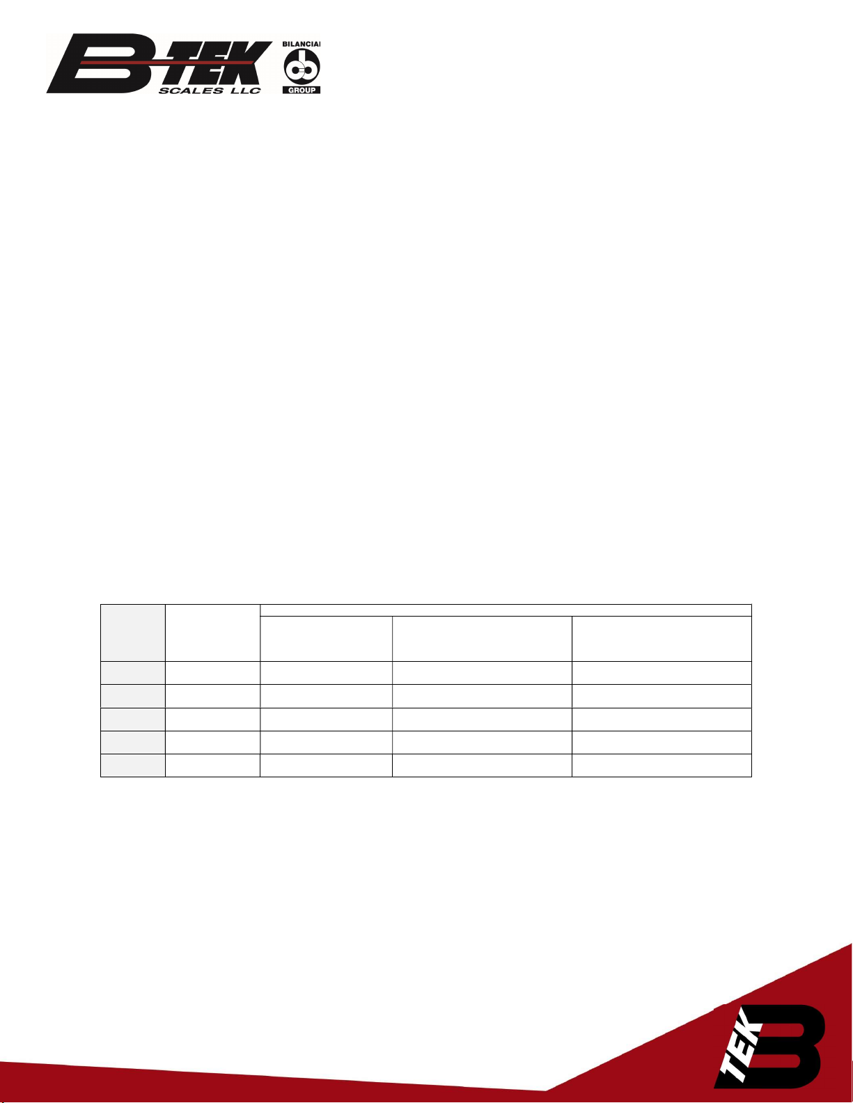
The list of the supported protocols.
Protocol
no. in the
menu
Protocol
Notes
The response to the
pressing button on the
operator panel
The response to not pressing the
button on the operator panel or the
lack of communication with the
control device
The response to the long,
simultaneous holding of the red and
green button on the operator panel
1 Standard Turning on the red, green
light
By default, the red light comes on Turning off the signalling device
2 Standard Turning on the red, green
light
The last status is saved Turning on the red and green light
3 Standard Turning on the red, green
light
The operator panel cable connection
failure is signalled: „XX”
Turning off the signalling device
4 Standard Turning on the red, green
arrow
The cable connection failure is
signalled „XX”
Turning on the red light
5 Pfister DWT800 Turning on the red, green
light
The cable connection failure is
signalled „XX”
Turning off the signalling device

Page | 8
Standard Protocols – Data Frame
The data frame consists of three bytes. The detailed construction is shown in Table 3.1.
The construction of the standard protocol frame.
Byte
no.
Value [hex] Description
0
0x3A
Frame start byte (‘:’)
1 0x00 – 0x7F Red light byte. Value 0x52 ‘R’ turns on the red light. Sending a different
value will result in displaying a character from the ASCII table.
2 0x00 – 0x7F Green light byte. Value 0x47 ‘G’ turns on the green light. Sending a
different value will result in displaying a character from the ASCII table.
Examples of frames:
„0x3A 0x52 0x20” – on the signalling device the red light will be turned on, the green light will be
turned off.
„0x3A 0x20 0x47” – on the signalling device the green light will be turned on, the red light will be
turned off.
„0x3A 0x3C 0x3E” – on the signalling device the red symbol of the left arrow and the green
symbol of the right arrow will be turned on.
„0x3A 0x20 0x5E” – on the signalling device the red symbol turns off and the green symbol of
the up arrow will be turned on.
Alpha characters and symbols will be displayed within the signal
area. Combinations of characters can be sent to assist color blind
individuals.
Interface transmission and communication speed
parameters
Interface Transmission parameters Communication speed
RS232, RS485, RS422,
CL
Data bits: 7, Parity: Odd, Even
Data bits: 8, Parity: None, Odd, Even
Stop bits: 1
300, 600, 1200, 4800, 9600, 14400,
19200, 28800, 38400, 57600, 76800,
115200, 230400
Table 1

Page | 9
Controller Connectors
The controller is a device responsible for the process of displaying the content by the light
signalling device.
det. A, det. B, det. C – LED module connectors; det. D – RS-485/RS-422 connector; det. E – 0/20mA digital current loop;
det. F – RS-232 connector; det. G – Ethernet connector; det. H – DEF microbutton; det. I – housing earthing soldering
point; det. J – network power supply connector
Fig. 7
LED Module Connectors
det. A, – operator panel connector (dry contact)
Fig. 8

Page | 10
Communication Connections
Table 2 contains the description of the connectors in the light signalling device. The connectors are
accessible after the disassembly of the back cover and the LED module mounted on this cover.
,
det. A – device front; det. B – controller; det. C – back cover; det. D – LED module;
Fig. 9
NOTICE!
The housing should be disassembled with the power supply disconnected.

Page | 11
Interface / Function Connector
markings Notes
STANDARD
RS-232 RA RXD line of the RS-232 interface. The line should be connected with
the weighing terminal TXD output
RK GND line of the RS-232 interface.
0/20mA (CL) digital
current loop
CA CL line of the current loop. Connected to weighing terminal TXD
output
CK GND line of the current loop interface.
RS-485 RS-422
A RS-485 and RS-422 interface non-inverting line
B RS-485 and RS-422 interface inverting line
GND
GND line of the RS-485 and RS-232 interfaces for use at risk of the
occurrence of a significant difference in the potentials of the display
mass and the weighing terminal mass
Operator panel
(dry contact)
GND GND line of the operator panel
IN1 Signal switching on the green light
IN2 Signal switching on the red light
LAN
2
Ethernet
TX+ Pin No. 1 of RJ–45
TX- Pin No. 2 of RJ–45
RX+ Pin No. 3 of RJ–45
RX- Pin No. 6 of RJ–45
Table 2
1. RS-232 connector:
For the communication purposes, the user connects with the controller via the RS-232 connector (Fig.
7) using the control module
2. RS-485 / RS-422 connector:
For the communication purposes, the user connects with the controller via the RS-485 or RS-422
connector (Fig. 7) using the control module.
3. 0/20mA digital current loop
For the communication purposes, the user connects with the controller via the digital current loop
connector, (Fig. 7) using the control module.
4. Operator panel (dry contact)
For the control purposes, the user manipulates the operator panel or relay contacts.
5. Ethernet
For the communication purposes, the user connects with the controller via Ethernet connector, (Fig.
7) using the control module.
2 All the connectors available as standard are located on the controller PCB. However, in the standard version, only the
cable connected to Ethernet connector is led out .

Page | 12
Automatic brightness control of the light
signalling device
In the standard version, the controller has a lighting sensor included, which is placed on the
LED panel. The device, in response to the ambient brightness, adjusts the light signalling device
brightness.
Initial start-up
Step 1: Make sure that all cables are properly connected,
Step 2: Make sure that all components have been installed in correct orientation,
Step 3 Connect the device to the mains power supply,
Step 4 The properly connected system will display the symbols "-" in the light fields, followed by
the hard space symbol ( _ ) in the bottom field . It means that the device is working according to
the default protocol. In 7 seconds, the signalling device will go into the default display state.
Changing Ethernet Settings
Wagset Software can be used to change the IP address. The TL-280 does not support a web
application like the BT-480.
WagSet 2: WagSet 2 Software Download
Open Wagset, click “Create own Protocol”, Select File, then “display network settings”
Change IP address under “New Display Settings”, then click Send.

Page | 13
Additional options
Operator panel Item# 841-500083
The operator panel is a separately offered accessory (additional option) which, among others,
can work with the device. On the panel, there are two monostable buttons that allow you to
change the information displayed by the signalling device. An example of the panel is shown in
Fig. 10
Fig. 10
Disposal and recycling
Packaging material recycling
The packaging elements must be segregated and then recycled in accordance with the local executive
regulations on waste disposal.
Device disposal
The device must not be disposed of as urban waste!
In accordance with the directive 2002/96/EC (WEEE), if the repair of the device is not economically
justified, the user must take the damaged or destroyed equipment to a special waste disposal.
Most common installation errors
1 Invalid configuration uploaded to the light signalling device.
2 Drilling additional mounting holes.
3 Installation not in accordance with the manual, wires facing up.
Table of contents
Popular Lighting Equipment manuals by other brands

Revolution Micro
Revolution Micro Avici 750 owner's manual

JB-Lighting
JB-Lighting Varyscan 4 1200HMI user manual

Federal Signal Corporation
Federal Signal Corporation CudaTriOptic 350205 installation instructions

NEXELO
NEXELO L177003NEX user manual

Magnum Lighting
Magnum Lighting ML-1000 Owner's manual and user's guide

Kasco
Kasco LED3C11 Operation & maintenance manual