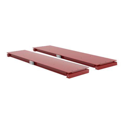
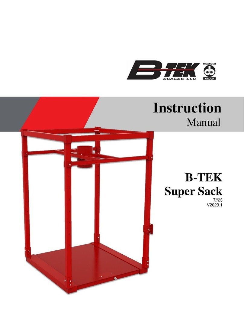
B-TEK Scales 4 Square User manual

4 Square
Clydesdale
Clydesdale Lift Deck
Workhorse
Drum Scale
RPS (Rocker Pin)
Models Include:

www.B-TEK.com 2020
Floor Scale Installation Manual
2

2020 www.B-TEK.com Floor Scale Installation Manual 3
Contents
Introduction Page 4
4 Square General Specs Page 5
Clydesdale Carbon General Specs Page 6
Clydesdale Stainless General Specs Page 7
Clydesdale Stainless Lift Deck General Specs Page 8
Workhorse Carbon General Specs Page 9
Drum Scale Carbon and Stainless General Specs General Specs Page 10
Rocker Pin Suspension (RPS) Carbon and Stainless General Specs Page 11
Installation Overview/Site Preperation Page 12
Pit Frame Installation Page 13
Unpacking Page 14
Assembling the Scale Page 15
Assembling the Scale - Workhorse Page 16
Assembling the Scale - Drum Page 16
Assembling the Scale - RPS Page 17
Anchoring the Scale - RPS Page 18
Opening and Cleaning - Lift Deck Page 19
Summing Board Connections Page 20
Floor Scale Wiring Diagram Page 21
Connecting the Indicator Page 22
Corner Adjustment and Calibration Page 22
Troubleshooting Page 23
Load Cell Replacement Page 24
Spare Parts Page 25

www.B-TEK.com 2020
Floor Scale Installation Manual
4
Introduction
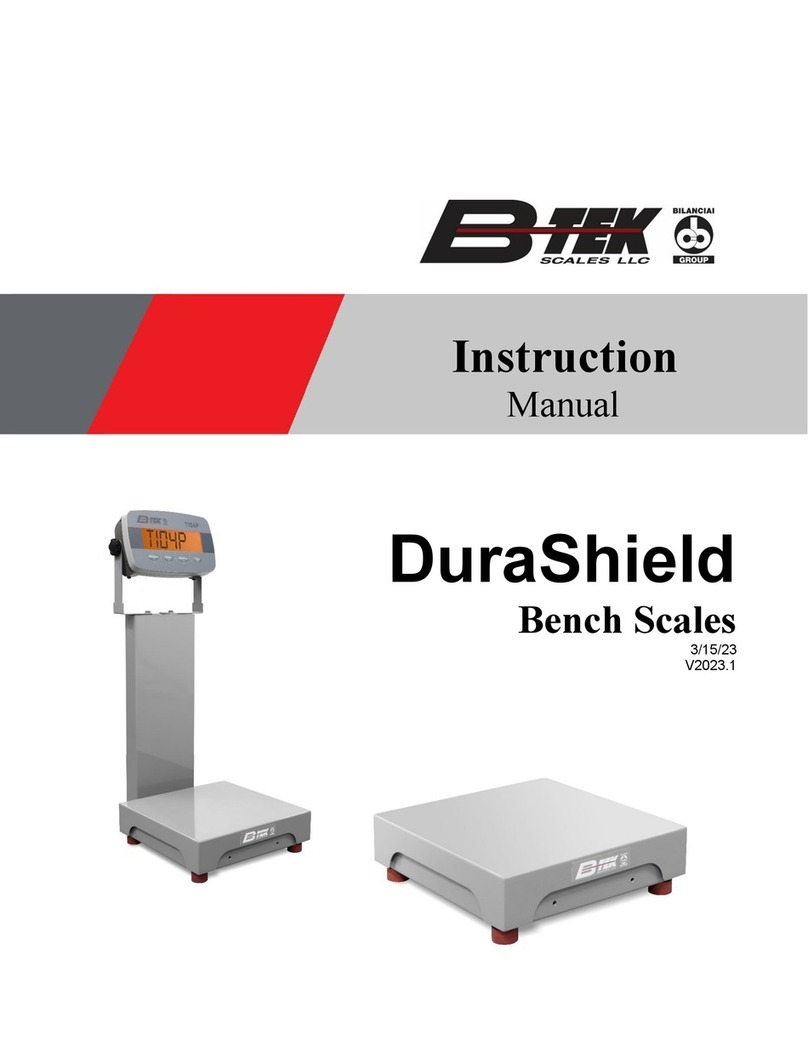
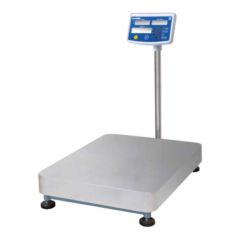
This manual is meant as an installation guide for the B-TEK oor scale. This includes the following models:
4 Square 4’ X 4’ carbon steel oor scale
BT-FC carbon steel oor scale
BT-FS stainless steel oor scale
BT-LD stainless steel Lift Deck
BT-RP Rocker Pin Suspension oor scale
BT-FCHD Workhorse platform scale
BS-CS-DS carbon steel Drum scale
BS-SS-DS stainless steel Drum scale
The 4 Square model of oor scale is a 4’ X 4’ platform with a NTEP approved capacity of 5,000 lbs.
The Clydesdale series of carbon and stainless steel oor scale is available in standard platform sizes from 2’ X 2’ to 10’
X 8’, which are NTEP approved. Capacities range from 500 lbs up to 20,000 lbs for NTEP approved capacities. Custom
sizes and other capacities are available, contact the factory for more information.
The Clydesdale Stainless Steel Lift Deck is available in standard platform sizes from 3’ x 3’ - 4’ x 6’, which are NTEP ap-
proved. Capacities range from 2,500 to 5,000 lb. Custom sizes and other capacities are available, contact the factory for
more information.
The Rocker Pin Suspension series of carbon and stainless steel oor scale is available in standard platform sizes from 3’
x 3’ to 5’ x 7’, which are NTEP approved. Capacities range from 500 lbs to 10,000 lbs. Custom sizes and capacities are
available, contact factory for more information.
The Workhorse series of carbon steel scales is a heavy duty version platform scale with standard size of 4’ X 4’ to 12’ X
10’. Capacities range from 20,000 lbs up to 40,000 lbs. The scale is NTEP approved. Custom sizes and other
capacities are available, contact the factory for more information.
The Drum scale series is available in both carbon and stainless steel versions. Standard platform sizes are 24” X 24”,
30” X 30”, 36” X 36” and 48” X 48”. Standard capacities are 1,000 lbs and 2,500 lbs, which are NTEP approved. Optional
accessories include integral and detachable access ramps, indicator column and portability kits. Custom sizes and other
capacities are available, contact the factory for more information.
No physical or electrical changes / alterations may be made to the scale during installation or use, which may void the
warranty. This includes removal, addition or modication of any steel or components, as well as electrical or program
related items.
Prior to installation it is the customer’s responsibility to verify that the equipment meets the requirements of the
application. Do not begin installation if this is unknown. It is the customer’s responsibility to ensure that the scale
equipment is operated within the manufacturer’s specications.
Any repairs must be performed by B-TEK Scales authorized service technicians.
Failure to comply with this policy voids all implied and/or written warranties.
2020 www.B-TEK.com Floor Scale Installation Manual 5
4 Square Carbon Steel Floor Scale
General Specications:
Certicate of Conformance: 94-092A4
Type: Above ground or pit
Scale Capacity: 5,000 lbs.
End Load Capacity: 150%
Scale Height: 3-1/2” nominal, adjustable
Available Sizes: 4’ x 4’
Weighbridge: Laser cut 3/16” carbon steel tread plate decking with structural channel sub-structure
Deck: Top access junction box, threaded lifting eye bolt hole in platform center
Paint System: Alkyd Enamel
Load Cell: (4) 4,000 lb., plated alloy steel, 350 Ohms, 3.0mV/V cells
Leveling Foot: B-TEK Level-Flex rubber feet - 2.5” diameter base
Junction Box: NEMA 4 berglass reinforced plastic (FRP) box with signal trim summing board
Accessories: Ramps, bump-guard, oor mounting plates
Warranty: 1-Year on weighbridge steel structure, load cells, junction box and summing board

www.B-TEK.com 2020
Floor Scale Installation Manual
6
Clydesdale Carbon Steel Floor Scale
General Specications:
Certicate of Conformance: 94-092A4
Type: Above ground or pit
Scale Capacity: 500 - 20,000 lbs. - NTEP Approved Capacities
End Load Capacity: 80% for 2.5K capacity
100% for 5K to 20K capacities
Scale Height: 4-3/8” nominal (2.5K - 10K-SE) adjustable
5-3/8” nominal (10K-LE - 20K) adjustable
Available Sizes: 2’ x 2’ - 8’ x 10’ - NTEP Approved Sizes
Any custom size platform available - 18” x 18” to 10’ x 12’
Weighbridge: Laser cut 1/4” carbon steel tread plate with formed channel sub-structure (2.5K - 10K-SE)
Laser cut 3/8” carbon steel tread plate with structural channel sub-structure (10K-LE & 20K)
Deck: Top access junction box, leveling foot adjustment holes.
Threaded lifting eye bolt holes: 5/8”-11 eyebolt
Paint System: Alkyd Enamel
Load Cell: Plated alloy steel, 350 Ohms, 3.0mV/V FM Approved
500lb capacity: (4) 250lb. cells
1K capacity: (4) 500 lb. cells
2.5K capacity: (4) 1,000 lb. cells
5K capacity: (4) 2,500 lb. cells by request in Clydesdale
5K capacity: (4) 4,000 lb. cells standard in Clydesdale
10K SE capacity: (4) 5,000 lb. cells (small envelope)
10K LE capacity: (4) 5,000 lb. cells (large envelope)
20K capacity: (4) 10,000 lb. cells
Optional Stainless Steel cells are available for any capacity listed above
Leveling foot: B-TEK stainless steel ball encapsulated foot
Junction Box: NEMA 4 berglass reinforced plastic (FRP) with signal trim summing board
Warranty: 3-Years on weighbridge steel structure,
2-Years on load cells, junction box and summing board

2020 www.B-TEK.com Floor Scale Installation Manual 7
Clydesdale Stainless Steel Floor Scale
General Specications:
Certicate of Conformance: 94-092A4
Type: Above ground or pit
Scale Capacity: 2,500 - 10,000 lbs.
End Load Capacity: 80% for 2.5K capacity
100% for 5K to 20K capacities
Scale Height: 4-3/8” nominal (2.5K - 10K-SE) adjustable
Available Sizes: 2’ x 2’ - 5’ x 7’ - Custom sizes upon request
Weighbridge: Laser cut 1/4” 304 stainless steel SMOOTH plate with structural channel sub-structure
Deck: Side access junction box, threaded lifting eye bolt holes
Finish: All exposed surface are media blasted to a clean, consistent appearance
Load Cell: Stainless steel (IP67), 350 Ohms, 3.0mV/V FM Approved
2.5K capacity: (4) 1,000 lb. cells
5K capacity: (4) 2,500 lb. cells by request in Clydesdale SS
5K capacity: (4) 4,000 lb. cells standard in Clydesdale SS
10K capacity: (4) 5,000 lb. cells
Optional hermetically sealed (IP68) cells are available for any capacity listed above
Leveling foot: B-TEK stainless steel ball encapsulated foot - 2.5” diameter base
Junction Box: NEMA 4 box with signal trim summing board
Warranty: 3-Years on weighbridge steel structure
2-Years on load cells, junction box and summing board

www.B-TEK.com 2020
Floor Scale Installation Manual
8
Clydesdale Stainless Steel Lift Deck Floor Scale
General Specications:
Certicate of Conformance: 94-092A4
Type: Above ground or pit
Scale Capacity: 2,500 - 5,000 lb
End Load Capacity: 80% for 2.5K capacity
100% for 5K capacity
Scale Height: 4-3/8" nominal height, adjustable
Available Sizes: 3' x 3' - 4' x 6' - Custom sizes upon request
Weighbridge: 1/4" 304 stainless steel SMOOTH plate with structural tube frame
Deck: Lifting handles on top plate with dual gas shocks to aid in raising
Finish: All exposed surfaces are media blasted to a clean, consistent appearance
Load Cell: Stainless steel (IP67), 350 Ohms, 3.0mV/V
2.5K capacity: (4) 1,000 lb
5K capacity: (4) 2,500 lb cells by request in Clydesdale
5K capacity: (4) 4,000 lb cells standard in Clydesdale
Optional hermetically sealed (IP68) cells are available for any capacity listed
above
Leveling foot: B-TEK stainless steel ball encapsulated foot - 2.5" diameter base
Junction Box: Side access NEMA 4 junction box with signal trim summing board
Warranty: 3-Years on weighbridge steel structure
2-Years on load cells, junction box, and summing board

2020 www.B-TEK.com Floor Scale Installation Manual 9
Workhorse Carbon Steel Heavy Duty
General Specications:
Certicate of Conformance: 18-061
Type: Above ground or pit
Scale Capacity: 20,0000 x 5lb
30,000 x 10lb
40,000 x 10lb
End Load Capacity: 100% for 20K and 40K capacities
66% for 30K capacity
Scale Height: 9” to 14” depending on platform size and capacity
Available Sizes: 4’ x 4’ - 12’ x 10’ - Custom sizes upon request
Weighbridge: 3/8” carbon steel SMOOTH or TREAD plate with WF-Beam sub-structure
Deck: Welded deck plate standard - Bolted deck plate optional
Paint System: Alkyd Enamel
Load Cell: B-TEK LCMT mount assembly bolted to WF-Beam sub-structure
20K capacity: (4) 10,000 lb., plated alloy steel, 350 Ohms, 3.0mV/V
30K capacity: (4) 10,000 lb., plated alloy steel, 350 Ohms, 3.0mV/V
40K capacity: (4) 20,000 lb., plated alloy steel, 350 Ohms, 3.0mV/V
Junction Box: Externally mounted NEMA 4X stainless steel junction box with signal trim summing board
Top access junction box available by request or standard when platform is installed in pit
Warranty: 5-Years on weighbridge steel structure
2-Years on load cells, junction box and summing board

www.B-TEK.com 2020
Floor Scale Installation Manual
10
Drum Scale Carbon & Stainless Steel
General Specications:
Certicate of Conformance: 94-092A4
Type: Low prole above ground
Scale Capacity: 1,000 & 2,500 lbs.
Scale Height: 1-1/2” nominal deck height
Available Sizes: 2’ x 2’ - 4’ x 4’ - Custom sizes upon request
Weighbridge: 1/4” carbon steel tread plate deck with live side rail design
1/4” 304 stainless steel SMOOTH deck with live side rail design
Deck: Side access FRP junction box, leveling foot adjustment holes in side rails
Paint System/Finish: Carbon: Alkyd Enamel
Stainless: All exposed surfaces are media blasted to a clean, consistent appearance
Load Cell: Plated alloy steel, 350 Ohms, 3.0mV/V
1K capacity: (4) 1,000 lb.
2.5K capacity: (4) 2,500 lb.
Stainless steel (IP67), 350 Ohms, 3.0mV/V
1K capacity: (4) 1,000 lb.
2.5K capacity: (4) 2,500 lb.
Junction Box: Carbon: NEMA 4 berglass reinforced plastic (FRP) with signal trim summing board
Stainless: NEMA 4 with signal trim summing board
Warranty: 3-Years on weighbridge steel structure
2-Years on load cells, junction box and summing board

2020 www.B-TEK.com Floor Scale Installation Manual 11
Rocker Pin Suspension (RPS)
Carbon & Stainless Steel
General Specications:
Certicate of Conformance: 94-092A4
Type: Above ground or pit
Scale Capacity: 1,000 x 0.2 lb
2,500 x 0.5 lb
5,000 x 1 lb
10,000 x 2 lb
Scale Height: 3” nominal (1,000 - 5,000)
3-1/2” nominal (10,000)
Available Sizes: 3’ x 3’ - 5’ x 7’ - Custom sizes upon request
Weighbridge: 1/4” carbon steel tread deck plate w/ formed channel sub-structure
1/4” 304 stainless steel smooth deck plate w/ formed channel sub-structure
Deck: Top access junction box, threaded lifting eye bolt holes: 5/8”-11 eyebolt
Paint System/Finish: Carbon: Alkyd Enamel
Stainless: All exposed surfaces are media blasted to a clean, consistent appearance
Load Cell: Stainless steel IP67, 350 Ohms, 2.0 mV/V, FM Approved
1,000 lb capacity: (4) 500 lb cells
2,500 lb capacity: (4) 1,250 lb cells
5,000 lb capacity: (4) 2,500 lb cells
10,000 lb capacity: (4) 5,000 lb cells
Leveling Foot: Fixed rocker pin - no height adjustment
Junction Box: NEMA 4 berglass reinforced plastic (FRP) with signal trim summing board
Warranty: 3-Years on weighbridge steel structure
2-Years on load cells, junction box and summing board

www.B-TEK.com 2020
Floor Scale Installation Manual
12
Installation Overview
Prior to installation of the scale it is important to have the proper location and application for the particular scale being
installed.
The typical procedure for the installation of scales covered in this manual will consist of the following:
• Choosing a site
• Ensuring that the scale installation site is level
• Unpacking the scale and any accessories or components
•Adjust the scale’s leveling / load feet
• Connection of an optional indicator
• Calibrating the scale
Installation Site Preparation
In order to ensure that the scale platform will not be loaded over its intended capacity take care that the installation site
will not allow unintended loads from being placed on the scale. Make sure that the scale location is not in the path of
forklift / tow motor trac or in the vicinity of falling objects.
If the scale has not been designed for a washdown application, do not allow the scale to be placed any area where water
may exist.
Take care that the cable between the scale and weight indicator is protected from being run over, cut, crushed or
susceptible to moisture.
The oor where the scale is being located should be within 1/4” of level across the length and width of the platform.

2020 www.B-TEK.com Floor Scale Installation Manual 13
Optional Pit Frame Installation Instructions
Cut out concrete 1’ larger than pit frame side (6” on each side) and dig out minimum of 8” deep. Note, you might need to
cut larger area if the surrounding concrete is not level to make angled approach to the scale a gradual slope.
Install 1” conduit from indicator location to side of pit frame the junction box is located. There is a rubber grommet on the
bottom side of the scale to run home run cable through.
Install drain in the middle of the pit frame, make sure it is the lowest point.
Place pit frame into installation location, use small pins on the corners of the frame and keep in place during concrete pour-
ing. Make sure the frame is level and at the correct height, recommend top of frame is ¼” higher than surrounding oor so
it does not become the areas drain point.
Pour concrete around and under the frame making sure concrete is supporting the four corner plates where the scales load
feet rest. All weight will be on these plates.
Let concrete cure for at least 24 hours.
Cut o home run conduit ush with oor so it does not contact the scale.
Run homerun cable through conduit leaving at least 5 feet of excess. You will need this length to move the scale out of the
pit when servicing.
Wire indicator and oor scale homerun per wiring diagram.
Purchase two 5/8” – 11 lifting eyes, 1/2” clevis, and rigging straps with over 1000 lb rated lifting capacity each. Make sure
straps are 4’ or longer to not lift with too much of an angle which can side load the lifting eyes and reduce lifting capacity.
Rent equipment to lift scale if needed.
Install oor scale into pit frame, with load feet not locked. Level scale to be even with the pit frame edge using at head
screwdriver. Make sure scale does not rock.
Lift scale back out of frame to set jam nuts on feet, then reinstall into pit frame. Make sure edges do not contact frame.
Power on indicator to verify correct operation and calibrate with certied weight.

www.B-TEK.com 2020
Floor Scale Installation Manual
14
2 threaded holes for Shoulder Style Lifting Eyes
Caution: The scale platform is heavy and can be awkward to
handle. Exercise extreme care when lifting the scale platform
to avoid personal bodily harm or damage to the equipment.
Remove the packing material and inspect the scale for any
visible damage occurring during shipment.
Note: On Clydesdale oor scales, sizes 36” X 36” and larger,
the load feet are packed inside the scale’s structural
channel, accessed through the top cover plate over the
junction box. If not packed internally, the load feet will be
sent separate from the scale, typically by UPS. On Rocker
Pin Suspension scale, rocker pins will be packed inside the
structural channel under the junction box cover.
Feet will not be packed internally in the following instances:
• Scale 30” X 30” or smaller
• Uses Level-Flex rubber base feet
• 3/4” or 1” threaded leveling feet
• All side access J-box scales
• Special applications
Clydesdale platforms will have threaded holes through the deck for using 5/8”-11 UNC threaded lifting eyes (not provided)
for lifting and moving the scale. 30” X 30” platforms and smaller have one threaded hole, 36” X 36” through 48” X 48” will
have two, and 60” X 60” and larger platforms will have four.
All B-TEK oor scales have threaded 5/8-11 tapped holes to receive shouldered lifting eyes. Important: Lifting forces must
be vertical to the lifting eyes. Ensure that shoulder style eye bolts are securely fastened to the scale before beginning to
lift.
Angle lifts should be avoided whenever possible. Angular lifts will signicantly lower working load limits of the lifting eyes.
Unpacking

2020 www.B-TEK.com Floor Scale Installation Manual 15
Assembling the Scale
Prior to installation of the scale the leveling feet must be threaded into the tapped through holes in each of the four load
cells bolted to the corner assembly in the scale.
In the case of a Workhorse heavy duty platform scale, four corner load cell assemblies with upper and possibly lower
plates will need to be assembled and attached to the scale.
The size of the leveling foot and load cell will vary depending on the capacity and design of the scale platform. It is
suggested to thread the load foot at least 75% through the thickness of the load cell. The height of the platform is
adjustable by the amount each leveling foot has been threaded into the cell.
IMPORTANT! Check to make sure the top of the load foot stem does not touch the scale by inserting too far. Visually
inspect the four corners adjustment holes, or make sure your nger ts between the load foot stem and scale frame. This
will cause the scale to not weigh correctly.
Using a level on top of the scale platform length and width, adjust the leveling feet so that the scale is with 1/4” of level in
both directions.
Once the scale has been leveled, tighten the jam nut against the bottom side of the load cell. When the jam nut is
loosened, adjustments to the leveling feet can be made using a at head screwdriver through the adjustment through
holes in the scale platform (except on workhorse platform scales).
Threading the leveling foot into the load cell
Verify gap between load foot stem and base.

www.B-TEK.com 2020
Floor Scale Installation Manual
16
Assembling the Scale- Workhorse
Workhorse heavy duty platform scales need to have the leveling foot threaded into the load cell, then the top mounting
plate will need to be attached to the scale weighbridge by four mounting bolts.
The leveling foot may sit on the oor, may include foot locating plates, or may rest on topside of a bottom mounting plate,
all depending on the application.
Assembling the Scale - Drum Scale
On drum scale the load cells are mounting inside the ends of the side tubes. There are cut-outs on the bottom side of the
tube to allow the feet to be threaded into the load cells.
Again, there are through holes on the top side of the side tubes to allow adjustment of the leveling feet with a at head
screwdriver. Do not allow threaded foot to contact the base.

2020 www.B-TEK.com Floor Scale Installation Manual 17
Place scale platform onto the base frame and verify pin alignment
through the inspection holes in the base frame. Orient the homerun
cable cord grip with the notch cut into the side of the base frame.
Watch for pinch points while installing the scale.
If permanently installing the scale, remove the scale platform from the
frame to install anchor bolts.
Important Note: Use only the supplied at head countersink bolts and anchors to install the scale. Standard hex
bolts will contact the scale platform and will cause inaccurate scale readings
Assembling the Scale - Rocker Pin Suspension
Place base frame onto the oor making sure the frame is level. Install pins into
all four corners.
The rocker frame design does not allow for height adjustments. Temporarily
place the scale onto the load pins to verify the scale does not rock from corner
to corner. If adjustments are needed, temporarily install shims under the base
frame to set the height, then ll area with epoxy grout making sure the area
under the load pin and anchor points are supported.

www.B-TEK.com 2020
Floor Scale Installation Manual
18
Anchoring Rocker Pin Suspension Frame
There are two anchor locations per corner. If shims are required, for additional
height, place supplied shims under each corner.
Drill 5/8” diameter hole, 2” into the cement. Do not ream or allow the drill to wobble.
Repeat this step for all of the anchor locations.
Clean the hole using compressed air and a nylon brush. Tap anchor into the drilled hole
until ush with cement.
Insert the setting tool into the end of the
anchor and expand the anchor by striking
the end of the setting tool with a hammer.
The anchor is set (fully expanded) when
the shoulder of the setting tool touches the
anchor.
Full expansion is necessary for proper
anchor performance.
The anchor is now ready to accept supplied hardware. Fully tighten all eight bolts.

2020 www.B-TEK.com Floor Scale Installation Manual 19
Opening and Cleaning - Lift Deck
To open scale: Locate hand hole(s) and latch(es). Pull ring towards you to release locking bolt. Once all locking bolts are
released lift deck.
Once deck is open, locate built in
locking/support bars.
Locate built in upper clevis pin(s). Remove cotter pin and
place support bar onto upper clevis pin. Place cotter pin
back into clevis pin to secure bar in place. Repeat process
for all remaining support bars.
The Lift Deck can now be safely cleaned/washed down.
Reverse steps to lower deck and latch into place.

www.B-TEK.com 2020
Floor Scale Installation Manual
20
Summing Board Connections
With the exception of the Workhorse, oor and drum scales are typically shipped with the load cells bolted in place and
pre-wired to the summing board.
Load cell wiring will be as follows for Sensortronic cells:
Note: For alternate interchangeable load cell brands check calibration certicate for wiring specics or refer to the drawing
below.
Make certain that all of the cord grip ttings on the junction box are tightened with a wrench so that the internal rubber
sleeve begins to protrude from the nut. Pull slightly on the cables to ensure they do not move.
This manual suits for next models
13
Table of contents
Other B-TEK Scales Scale manuals

B-TEK Scales
B-TEK Scales DuraShield User manual

B-TEK Scales
B-TEK Scales BT-BC User manual

B-TEK Scales
B-TEK Scales WorldWEIGH C100 Series User manual

B-TEK Scales
B-TEK Scales TensionLink WS User manual

B-TEK Scales
B-TEK Scales AX200 User manual

B-TEK Scales
B-TEK Scales WorldWEIGH PGE-W Series User manual

B-TEK Scales
B-TEK Scales WorldWEIGH C200 Series User manual

B-TEK Scales
B-TEK Scales Above-ground User manual

B-TEK Scales
B-TEK Scales Skynet Installation and maintenance instructions

B-TEK Scales
B-TEK Scales Centurion-DT User manual