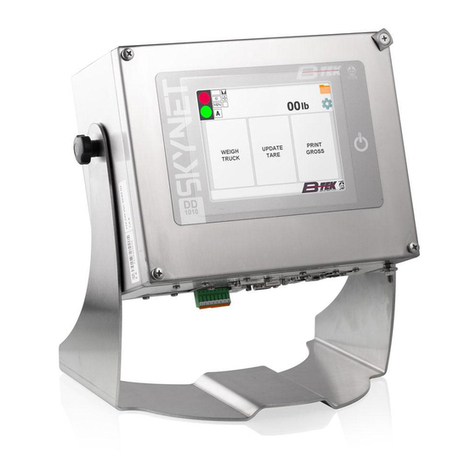
B-TEK Scales DD1010 User manual

Page | 1
DD1010 Skynet Scale Setup
& Troubleshooting
BTEK
September
2021
This guide is intended to supplement and simplify other product technical manuals. The focus is
to instruct on setting up / troubleshooting the scale and communication ports on a DD1010
Skynet indicator. See Use, Maintenance, and Installation manual for overall product instruction,
and the start manual for features accessed during startup of the indicator.

Page | 2
Table of Contents
MAIN SCREEN................................................................................................................................................4
Passwords .................................................................................................................................................4
Adding a Scale...............................................................................................................................................5
Scale Metrological Seal .................................................................................................................................6
Configuring Scales.........................................................................................................................................7
Calibration Buttons.......................................................................................................................................8
Scale Calibration............................................................................................................................................9
Calibrating Analog Scale............................................................................................................................9
Calibrating Digital Scale...........................................................................................................................10
Diagnostics..................................................................................................................................................13
Diagnostics and Scale Event Log .............................................................................................................14
Replacing Digital Load Cells.........................................................................................................................15
Startup Screen (Touch within 5 seconds) ...................................................................................................16
Test Scale ................................................................................................................................................19
Test Digital Cells......................................................................................................................................20
Touch Screen Calibration............................................................................................................................22
Printer and Remote Display Wiring ............................................................................................................23
Digital Scale Wiring .....................................................................................................................................24
Digital Junction Board.........................................................................................................................24
Analog Scale serial connection ...................................................................................................................25
Serial Connections.......................................................................................................................................25
COM2 serial link / COM6&7 Skynet........................................................................................................25
COM3 serial link / COM 4 Skynet........................................................................................................26
RS232 connections..................................................................................................................................26
RS422 connections..............................................................................................................................27
RS485 connections..............................................................................................................................27
INPUTS / OUTPUTS......................................................................................................................................28
Skynet I/O Connector..........................................................................................................................29
Input connection.....................................................................................................................................29

Page | 3
Output connection..................................................................................................................................29

Configuring a printer...................................................................................................................................30
Configuring a Scoreboard ...........................................................................................................................31
Setting IP Address and Time and Date........................................................................................................32
Network Scale from DDX0X0 ......................................................................................................................33
Sharing Database ........................................................................................................................................35
Primary DD:.........................................................................................................................................35
Setup Slave DD....................................................................................................................................36
Software Update.........................................................................................................................................37
Spare Parts and Useful Items......................................................................................................................38

Page | 4
MAIN SCREEN
When you power up the indicator you will see the main screen in the image below. Along the top you
will see the traffic light indicator, the weight display, a folder icon, and a gear icon from left to right.
The folder icon opens a diagnostic area that allows a service technician or state auditor to check the
event log and other diagnostic information from the front panel.
In the bottom right corner, you will see the logo button which –when held down –will prompt you for a
password to enter the configuration section of the software.
Passwords
Hold the B-TEK Button until it turns red, passwords as follows:
Technical Menu –2835
Operator Menu / Application Settings –2050
Password Reset –Call B-TEK Technical Support
N-TEP Screen View (Displays all platforms for testing)- 6837

Page | 5
Adding a Scale
At the main screen press and hold the BTEK Logo, Once Red enter 2835, scroll to page 8 of 11.
1. Press Metro
2. Press Scale Configuration
3. Press Add
4. Select the Internal scale. If the scale board already contain existing data, everything will be
automatically copied on the CORE processor. If an invalid scale type error occurs, refer to the
Start menu manual to configure scale hardware (Touch within 5 seconds screen during
startup).
5. Press on the Scale A or B to Configure
6. Parameters of the Internal Scale A or B
7. Save

Page | 6
Scale Metrological Seal
1. When the scale background is red, the metrological module is sealed. To
remove the seal, press the calibration button or enter a seal password to
enter inside the Setup for Metrological modification and Calibration.
2. When the scale background is grey, the Instrument is not protected, so it is
possible to enter inside the Setup and make Metrological modifications and
Calibration.
3. Press Seal Management to view, change, or unseal the device.
4. The seal management area is where the seal type can be changed and where
the software seal password can be entered. See software seal document for
password.
1

Page | 7
Configuring Scales
1. Features (Metrological parameter of the internal scale A) –The parameters
“Legal scale” & “Law” is set in the Seal Management section on page 50.
2. Specific (Analogue scale parameters, and number of digital cells)
3. Tare parameters
4. Zero parameters
5. Stability parameters
6. Secondary unit of measures
7. Fields management (Allow to define a Single range or a Multirange Scale)

Page | 8
Calibration Buttons
1. Calibration data (Displays internal conversion points, and ability to change the
points manually)
2. Calibration Procedures (Allow to calibrate the instrument)
Note: “Zero Full Scale” is selection to perform a zero and span calibration.
3. Synchronize
Restore Parameters- restores to the previous scale configuration from core
board to scale card. After board replacement, update scale serial number
first, then restore parameters.
Update Scale Serial Number - synchronize core processor to scale board.
See Digital Load cell replacement section if cells to scale and scale to cells is displayed.

Page | 9
Scale Calibration
Calibrating Analog Scale
At the main screen press and hold the BTEK Logo, Once Red enter 2835 and tap the Metro
Button on page 8 of 11. Press scale configuration, then on Scale A or B.
1. Press the calibration Button or enter software seal to access parameters.
After removing metrological seal, the background will turn to gray and the
shield symbol will disappear. Press A to enter parameters.
2. Press Calibration Procedures to enter inside the calibration menu.
3. Chose the calibration type to perform. For example, Zero Full Scale will be a
zero and span calibration. The full-scale weight value will be changed to your
test load value.
4. Check if the scale is empty and press Calibrate to calibrate the dead load.
5. Press on the Weight Box (120000 lb in the example), enter the test weight,
load the weight on the platform, and press enter.
6. Press Calibrate to execute the span calibration.

Page | 10
7. Confirm the calibration of the Scale (Zero –Full Scale)The instrument will
automatically escape and save the calibration on the Core and Scale Board
side, then confirm the calibration was saved.
Calibrating Digital Scale
At the main screen press and hold the BTEK Logo, Once Red enter 2835 and tap the
Metro Button. Tap on Scale A
1. Select the specific parameter
2. Set the number of load cells connected (4 in the example)
3. Close and save the changes. Now the terminal is programmed with all the
metrological information and how many load cells are connected

Page | 11
4. Select Calibration Procedure
5. Select Eccentric Load
6. Press calibrate / “coefficienti calcolati” to starting the Eccentric procedure
7. Select the calibration Type (By side or by ID). In the example we will use the
calibration by side
8. Calibration of the dead load. Check if the scale is empty and press calibrate /
“coefficienti calcolati” to calibrate the dead load
9. At the end of the Dead load calibration the DD ask to load the cell in position
1. When weight is centered over cell, press Calibrate / “coefficienti calcolati”

Page | 12
10. Unload the cell 1 and move the weight on the top of the load cell that will be
addressed as 3. Then press calibrate / “coefficienti calcolati”.
11. 8. Unload the cell 3 and move the weight on the top of the load cell that will
be addressed as 4. Then press calibrate / “coefficienti calcolati”.
12. 9. Unload the cell 4 and move the weight on the top of the load cell that will
be addressed as 2. Then press calibrate / “coefficienti calcolati”.
13. 10. The calibration of the 4 load cells is finished. This procedure is also used
by the terminal to address the single load cells. The DD1010 ask to calculate
the Coefficients of correction. Press Calculate coefficients.
14. The terminal shows the coefficient of correction and ask to save the values.
15. The Eccentric calibration is finished.
16. Follow Steps 1-7 under Analog calibration to complete a zero / span
calibration.

Page | 13
Diagnostics
The diagnostics screen can be access from the yellow folder on the top right of the weigh screen.
Scale Diagnostic Log- The scale diagnostic log will display scale card and load cell errors by date and
time. The diagnostic log must be turned on in the meteorological settings to record and view the
events.
Diagnostics- Use this button to troubleshoot scale and load cell issues. Additional details are on the
next page.
Metrological Info- View firmware revisions and seal status of the metrological equipment.
Event Logger- Displays and prints the audit trail, press “metrological only”for the local auditor.

Page | 14
Diagnostics and Scale Event Log
1. Press scale diagnostic log, then select the scale.
2. The scale statistics is displayed.
3. Press scale events, the diagnostic log is now displayed. Bil is the scale card,
and C# is the individual cells that have errors.
4. From the main folder page, Press diagnostics, the current weight or error is
displayed with high resolution weight.
5. Press Cells, all load cell counts are displayed, or ----- if not communicating.
The detailed information from each cell can be viewed by pressing on the load
cell numbers above the details.

Page | 15
Replacing Digital Load Cells
Install a new, un-addressed (Defaulted) loadcell in the scale.
**Prior to performing this procedure, the DD should be showing Error Code 07, or
08 meaning that it sees all the loadcells, it does not recognize one of them. If its
reading Error Code 01, then you have another problem that needs corrected
before you do this procedure.**
1. At the main screen press and hold the BTEK Logo, Once Red enter 2835 and
press the Metro Button on page 8 of 11. Press scale configuration, then on
Scale A or B.
2. Select: “SYNCHRONIZE”
**Note: If you do not see the SYNCHRONIZE icon, then the scale is software
sealed. Follow the procedure to unseal the scale prior to going any
further!!**
3. Select the box on the RIGHT that says: “Scale to Cells”, and wait a few
seconds.
4. A box will appear and you will need to answer “YES”.
**Important** A box should now appear where you need to click on “OK”. If
this box does not appear, you need to select the “Scales to Cells” icon again.
If you do not follow this step, you will forfeit everything you have done so far
and will have to redo it all again.
5. Select: “X” to close.
6. Select: “SAVE”.
7. Cycle power on the DD. It takes almost 30 seconds for the scale to boot up.
8. Repeat steps 1 and 2.
9. Select the box on the LEFT that says: “Cells to Scale”, and wait a few seconds.
10. A box will appear and you will need to answer “YES”.
**Important** A box should now appear where you need to click on “OK”. If
this box does not appear, you need to select the “Cells to Scale” icon again. If
you do not follow this step, you will forfeit everything you have done so far
and will have to redo it all again.
11. Select: “X” to close.
12. Select: “SAVE”.
13. Exit out of all menus until you get to the normal weighing screen and you
should now see weight.

Page | 16
Startup Screen (Touch within 5 seconds)
The startup area can be useful for setting up new scale cards, troubleshooting hardware, and
digital load cells. Normally setup and calibration is done from the application (B-TEK Button).
See the start manual for other features. You will notice some of the screens say “Flynet”,
B-TEK rebranded the Bilanciai version to DD1010 Skynet to addend the existing N-TEP COC.
Enter password 607524, then press Login

Page | 17
Tap Utility, then Test Hardware
Select Test Scale

Page | 18
The test scale page is below, when the card is read by the main board the dip switch settings,
firmware release, and serial number will be displayed.
Update Firmware- Load scale cards firmware onto a USB storeage device, then press update
firmware. Do not proceed unless you have the firmware loaded and ready.
Dip Switch Settings on the scale board
Value Scale number Type
00 Scale 1 (fixed value) Hardware
01 Scale 2 (fixed value) Hardware
10 Scale 3 (fixed value) Hardware
11 Software value - Program scale number with Change NBR Button

Page | 19
Test Scale
Use this feature if you want to check the linearity of the converters without changing calibration.
1. Press 'ZERO' button when the simulator is in the 0 mV position.
2. Rotate the dial to the 2 mV position and press the 'MAX CAPACITY' button.

Page | 20
Test Digital Cells
Address SET- From this window all the working load cells connected to the scale board are
visible. To change the address of a load cell, press the button 'SET' (set number) beside the
address box.
Keep in mind, if you keep track of the serial numbers position in a new scale installation, you
can manually address the system to check the scale before a test truck is available.
Coefficient SET- Coefficients can also be changed manually from this screen, (Can also be
changed in the calibration section of the application software). The eccentric calibration is the
better option when needing to adjust two or more sections. When only one cell or section is
needing adjusted change the coefficient up or down .001 for every 20 lbs of adjustment.
Example: Section 2 is reading 40lbs heavy. Currently cell 3 is .99865, and cell 4 is 1.00162.
To bring down the entire section 40 lb enter cell 3 at .99765 and cell 4 1.00062. Reboot the
cells, then start the application to retest the scale.
Factory Default Cells - To factory default a load cell, press the calibration button on the main
board, the seal status will turn green, then press the “DEF” button.
Table of contents
Other B-TEK Scales Scale manuals

B-TEK Scales
B-TEK Scales Skynet Installation and maintenance instructions

B-TEK Scales
B-TEK Scales AX200 User manual

B-TEK Scales
B-TEK Scales Super Sack User manual

B-TEK Scales
B-TEK Scales WorldWEIGH C200 Series User manual

B-TEK Scales
B-TEK Scales AquaShield Series User manual

B-TEK Scales
B-TEK Scales Centurion-DT User manual

B-TEK Scales
B-TEK Scales WorldWEIGH PGE-W Series User manual

B-TEK Scales
B-TEK Scales DuraShield User manual

B-TEK Scales
B-TEK Scales TensionLink WS User manual

B-TEK Scales
B-TEK Scales Above-ground User manual