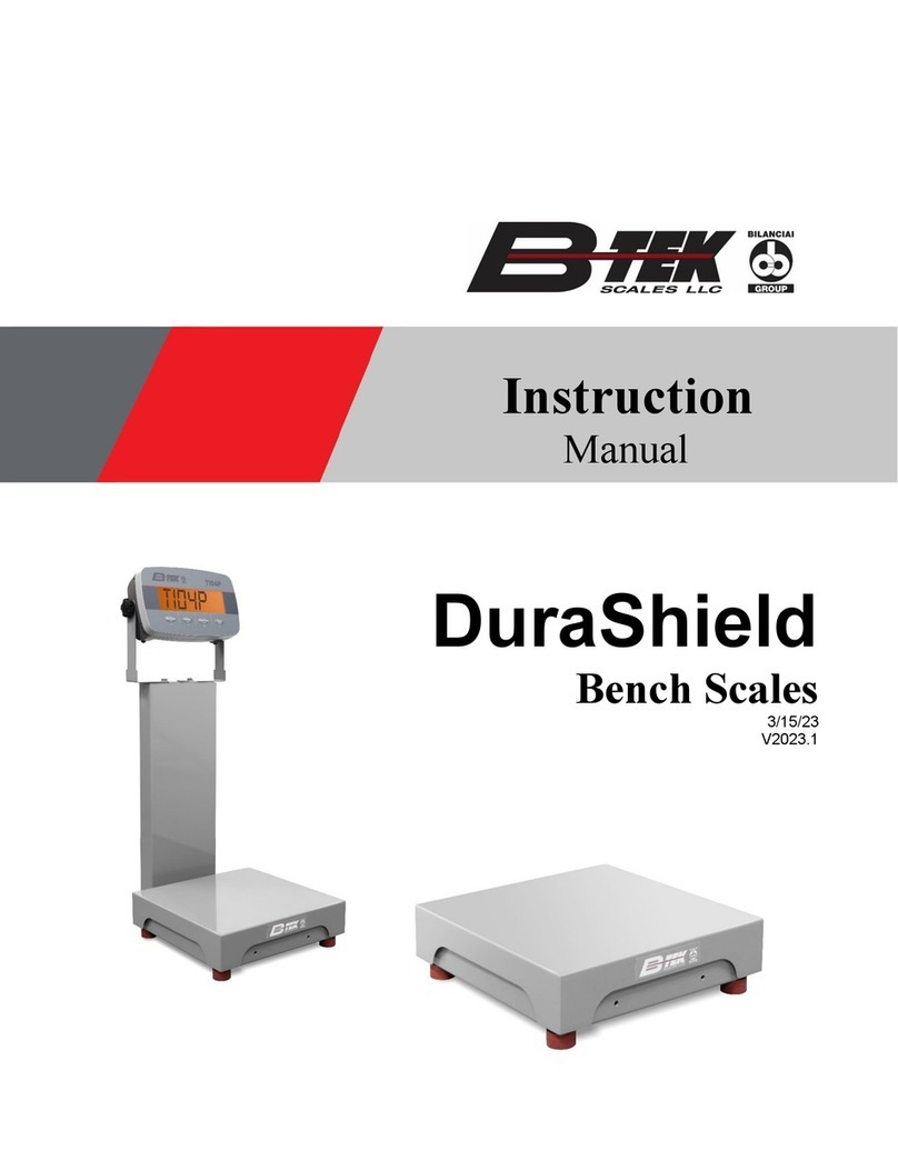
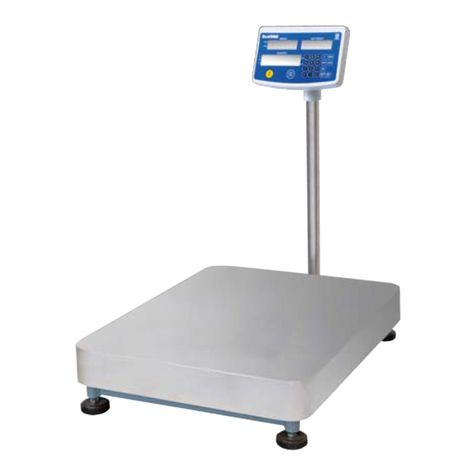
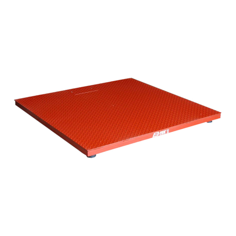
B-TEK Scales BT-BC User manual

2014 SP Series Bench Scale Manual
11/2014
Industrial Bench and Portable Scale
Includes Models:
BT-BC carbon steel
BT-BS stainless steel
BW-CSPS portable scale
BW-SSPS portable scale
BW-CSPS-WB Weigh Buggy
BW-SSPS-WB Weigh Buggy
Instruction Manual

2
Contents
Introduction Page 3
Installation Overview Page 8
Unpacking Page 9
Assembling the Scale Page 1
Connecting the Indicator Page 12
Trouble Shooting Page 13
Load Cell Replacement Page 14
Spare Parts Page 15

3
Introduction
This manual is meant as an instruction guide for the B-TEK bench and ortable scale
series of roducts. This includes the following models:
BT-BC carbon steel single point industrial bench scale
BT-BS stainless steel single point industrial bench scale
BW-CSPS Weigh-A-Round carbon steel portable scale
BW-SSPS Weigh-A-Round stainless steel portable scale
BW-CSPS-WB carbon steel portable Weigh Buggy
BW-SSPS-WB stainless steel portable Weigh Buggy
The Industrial Bench Scale Series of carbon and stainless single oint scale is
available in standard latform sizes from 12” X 12” to 30” X 30”, which are NTEP
a roved. Ca acities range from 5 LBS u to 500 LBS for NTEP a roved ca acities.
Custom sizes and other ca acities are available, contact the factory for more
information.
The Weigh-A-Round series of carbon and stainless steel ortable scales are a version
of the single oint scale with standard sizes of 24” X 18” and 30” X 24”. Ca acities
range from 100 LBS u to 1,500 LBS. The scale is non-NTEP. Custom sizes and other
ca acities are available, contact the factory for more information. O tional accessories
include rear swivel wheels and a ush handle assembly.
The Weigh Buggy portable scale series is available in both carbon and stainless
steel versions. The standard design is su lied with a 12 cubic foot ho er and a
ca acity of 1,000 LBS. The scale is non-NTEP
No hysical or electrical changes / alterations may be made to the scale during
installation or use, which may void the warranty. This includes removal, addition or
modification of any steel or com onents, as well as electrical or rogram related items.
Prior to installation it is the customer’s res onsibility to verify that the equi ment meets
the requirements of the a lication. Do not begin installation if this is unknown. It is the
customer’s res onsibility to ensure that the scale equi ment is o erated within the
manufacturer’s s ecifications.
Any re airs must be erformed by B-TEK Scales authorized service technicians.
Failure to com ly with this olicy voids all im lied and/or written warranties.

4
Single Point Carbon Steel Base
Industrial Bench Scale
General Specifications:
• Certificate of Conformance: 96-169A2
• Ty e: Single oint bench scale
• Scale Ca acity: 5 - 500 lb. - NTEP A roved Ca acities
• Scale Height: 4” and 5-1/4”
• Available Sizes: 8” x 8” to 30” x 30” - custom sizes u on request
• Weighbridge: Carbon steel heavy duty formed base frame and structural tube s ider
• Column: OPTIONAL 24” tall structural tube column with indicator mounting late
• Platter: Heavy gage 304 stainless steel
• Finish: E oxy aint finish on base frame and s ider
• Load Cell: Anodized aluminum single oint load cell
Environmentally sealed (IP67), 350 Ohms, 2.0 mV/V, FM A roved
10’ cable length
• Overload Protection: 5- oint system
• Warranty: 2-Years on weighbridge steel structure
1-Year on load cell

5
Single Point Stainless Steel Base
Industrial Bench Scale
General Specifications:
• Certificate of Conformance: 96-169A2
• Ty e: Single oint bench scale
• Scale Ca acity: 5 - 500 lb. - NTEP A roved Ca acities
• Scale Height: 4” and 5-1/4”
• Available Sizes: 8” x 8” to 30” x 30” - custom sizes u on request
• Weighbridge: 304 stainless steel heavy duty formed base frame and structural tube s ider
• Column: OPTIONAL 24” tall structural tube column with indicator mounting late
• Platter: Heavy gage 304 stainless steel
• Finish: Media blast finish on base frame and s ider
• Load Cell: Anodized aluminum single oint load cell
Environmentally sealed (IP67), 350 Ohms, 2.0 mV/V, FM A roved
10’ cable length
OPTIONAL stainless steel hermetically sealed (IP68) load cell
• Overload Protection: 5- oint system
• Warranty: 2-Years on weighbridge steel structure
1-Year on load cell

6
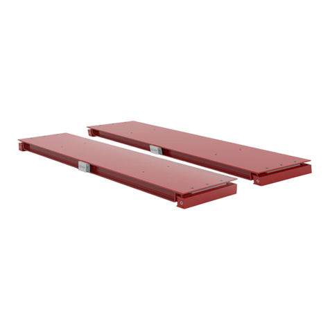
Weigh-A-Round
Carbon and Stainless Portable Scales
General Specifications - Carbon Steel:
• Certificate of Conformance: NON-NTEP
• Ty e: Portable single oint weighing latform
• Scale Ca acity: 100 - 1,500 lbs.
• Platform Height: 6-9/16” nominal
• Available Sizes: 24” x 18” & 30” x 24” - custom sizes u on request
• Weighbridge: Heavy duty structural channel base frame and structural tube s ider
Standard: (4) fixed, in-board mounted 5” heavy duty wheels
Optional: (2) fixed in-board and (2) rear mounted swivel wheels
• Column: 48” tall structural tube column with handle gri s and to late for indicator
• Platter: 304 stainless steel
• Finish: E oxy aint finish on base frame and s ider
• Load Cell: Anodized aluminum “brick ty e” single oint load cell
Environmentally sealed (IP67), 350 Ohms, 2.0 mV/V, FM A roved
• Warranty: 2-Years on weighbridge steel structure
1-Year on load cell
General Specifications - Stainless Steel:
• Certificate of Conformance: NON-NTEP
• Ty e: Portable single oint weighing latform
• Scale Ca acity: 100 - 1,500 lbs.
• Platform Height: 6-9/16 nominal
• Available Sizes: 24” x 18” & 30” x 24” - custom sizes u on request
• Weighbridge: Heavy duty 304 stainless steel structural channel base frame and structural tube s ider
Standard: (4) fixed, in-board mounted 5” heavy duty wheels
Optional: (2) fixed in-board and (2) rear mounted swivel wheels
• Column: 48” tall structural tube column with handle gri s and to late for indicator
• Platter: 304 stainless steel
• Finish: All ex osed surfaces are media blasted to a clean, consistent a earance
• Load Cell: Anodized aluminum “brick ty e” single oint load cell
Environmentally sealed (IP67), 350 Ohms, 2.0 mV/V, FM A roved
• Warranty: 2-Years on weighbridge steel structure
1-Year on load cell

7
Carbon and Stainless Portable Hopper Scale
Weigh-Buggy
• 1,000 lb. ca acity
• 12cu/ft ho er ca acity
• Lever actuated slide gate
• Front / Bottom material discharge
• All steel construction
• Two- art e oxy aint
• Fixed front wheels
• Swivel rear wheels
• Dual load cell design
• T103SB weight indicator (included)
• Stainless indicator housing
• Built-in rechargeable battery
• U to 70 hour battery life
• 1” backlit LCD dis lay

8
Installation Overview
Prior to installation of the scale it is im ortant to have the ro er location and a lication
for the articular scale being installed.
The ty ical rocedure for the installation of scales covered in this manual will consist of
the following:
• Choosing a site
• Ensuring that the scale installation site is level
• Un acking the scale and any accessories or com onents
• Adjust the scale’s leveling / load feet
• Connection of an o tional indicator
• Calibrating the scale
Installation Site Preparation
In order to ensure that the scale latform will not be loaded over its intended ca acity
take care that the installation site will not allow unintended loads from being laced on
the scale. Make sure that the scale location is not in a location where items heavier than
the scale’s ca acity may accidently be laced on the scale or in the vicinity of falling
objects.
If the scale has not been designed for a washdown a lication, do not allow the scale to
be laced any area where water may exist.
Take care that the cable between the scale and weight indicator is rotected from being
run over, cut, crushed or susce tible to moisture.
The floor or latform where the scale is being located should be within 1/4” of level
across the length and width of the latform.

9
npacking
Caution: The scale latform is heavy and can be awkward to handle. Exercise extreme
care when lifting the scale latform to avoid ersonal bodily harm or damage to the
equi ment.
Remove the acking material and ins ect the scale for any visible damage occurring
during shi ment.
On Industrial Bench scales, for shi ing ur oses the latter is fli ed u side down
and the base and s ider assembly set inside.
Remove the com onents from the shi ing box. The load cell will be bolted in lace
and the leveling feet threaded into the corner lates of the base. Fli the base over so
that the leveling feet are sitting on a flat level service. The threaded leveling feet are
adjustable. Adjust as needed referring to the leveling bubble on the scale assembly.
Place the latter over the s ider assembly.

10
OVERLOAD STOP
TIGHTENED FOR
SHIPPING
OVERLOAD STOP
ADJUSTED FOR
WEIGHING
Assembling the Scale
Note that the four threaded overload sto s in the corners of the base assembly have
been adjusted to be tight against the underside of the s ider tubes for shi ing.
Prior to use the overload sto s must be adjusted to allow a roximately a to 1/4” ga
(de endent u on ca acity) between the to of the bolt head and bottom of s ider
tubes. To adjust the overload sto s loosen the jam nut against the corner late and
then turn bolt head to ro er distance. Retighten the jam nut to revent the overload
sto s from moving. If the s ider tubes “bottom out” against any overload sto s with a
load equal to or less than the maximum ca acity, readjust the overload sto s.
Place the latter over the s ider assembly after all adjustments have been made.

11
The Weigh-A-Round Portable Scale and the Weigh Buggy will be shi ed fully
Assembled, ty ically on a skid. The overload sto s have been already adjusted tight
against the s ider assembly at the factory for shi ing ur oses. These will need
adjusted to allow a roximately a 1/4” ga (de endent u on ca acity) between the to
of the bolt head and bottom of s ider tubes. To adjust the overload sto s loosen the
jam nut against the corner late and then turn bolt head to ro er distance. Retighten
the jam nut to revent the overload sto s from moving. If the s ider tubes “bottom out”
against any overload sto s with a load equal to or less than the maximum ca acity, re-
adjust the overload sto s.
Place the latter over the s ider assembly after all adjustments have been made.

12
Connecting the Indicator
De ending on the ty e of scale ordered, the cable from the load cell to the weight
indicator will most likely need to be connected. Scales that are ordered re-calibrated
or a ty ical Weigh Buggy scale will have the connection already made.
Weigh Buggies are constructed with two load cells and require a junction box with
summing board which is included with the scale. The cable between the junction box
and indicator will be rewired rior to shi ing from the factory.
The load cell su lied will ty ically be a Tedea with a 10 foot cable. Do not cut the
cable as the load cell is tem erature com ensated for an exact length of 10 feet.
Check the manual su lied with your articular indicator to determine the ro er load
cell cable in ut connections. Refer to the following chart for load cell wire codes:
Wire Color Code Function
Green + Excitation (In ut)
Black - Excitation (In ut)
Blue + Sense
Brown - Sense
Red + Signal (Out ut)
White - Signal (Out ut)
For alternate interchangeable load cell brands check calibration certificate for wiring
s ecifics. If su lied with a junction box, make certain that all of the cord gri fittings
are tightened with a wrench so that the internal rubber sleeve begins to rotrude from
the nut. Pull slightly on the cables to ensure they do not move.
Refer to your articular indicator’s manual for s ecific calibration rocedure. In general
you should lace the indicator into “calibration” mode and erform a zero calibration
with no weight on the scale. Then lace test weights on the scale equal to 70%-80% of
the scale’s total ca acity. If several test weights are being used they should be s aced
evenly around the latform.
Remove all test weights and check the zero reading on the indicator. If necessary,
re eat the above rocedure for calibration and then remove the indicator from its
calibration model.

13
Trouble Shooting
• The indicator does not o erate (no dis lay): - Check power source / plug
- Fuse in indicator has blown
- Connection cable is cut
- Incorrect connection to scale
• The indicator dis lay stays at zero: - Faulty indicator
- Incorrect connection for load cell wires
• Varying weight indication: - Scale platform is not level
- Check for items under platform (binding)
- oad cell or cable water damage
- vibration near scale (remove source)
- Faulty indicator
• Consistently weighing incorrectly: - Scale platform / cover is binding
- Overload stops are set too high
- Indicator not calibrated correctly
- oad cell is damaged

14
Load Cell Replacement
If a load cell should need re laced, verify the art number with the s are arts list in
this manual. Re lacement cells should be of the same ca acity of the cell that is being
re laced.
Lift the scale’s cover latter ex osing the s ider assembly and load cell. Unbolt the
s ider from the load cell, and then the load cell from the base. For Weigh Buggy
ortable ho er scales, use of a jib crane or fork lift will be required to remover the
ho er assembly.
Disconnect the wire leads from the indicator or the summing board in the case of two
load cells in a Weigh Buggy.
Prior to bolting the new load cell in lace, route the cable back through the scale
and reconnect the wire leads to the indicator or the summing board.
Torque the mounting bolts er the following chart:
BOLT DIAMETER TORQUE
1/4”-2 14 FT. LBS.
5/16”-18 29 FT. LBS.
Recalibrate scale er the revious instructions in this manual and er the indicator’s
manual.

15
Spare Parts
Part Number Item Notes
814-100092 50kg single oint load cell For 12” X 12” 50 LB. scale
814-100093 75kg single oint load cell For 12” X 12” 100 LB. scale
814-100087 100kg single oint load cell For 12” X 12” 150 LB. scale
814-100087 100kg single oint load cell For 12” X 12” 200 LB. scale
814-100080 200kg brick load cell For 12” X 12” 300 LB. scale
814-100082 300kg brick load cell For 12” X 12” 500 LB. scale
814-100092 50kg single oint load cell For 18” X 12” 50 LB. scale
814-100093 75kg single oint load cell For 18” X 12” 100 LB. scale
814-100087 100kg single oint scale For 18” X 12” 200 LB. scale
814-100078 150kg brick load cell For 18” X 12” 250 LB. scale
814-100082 300kg brick load cell For 18” X 12” 500 LB. scale
814-100092 50kg single oint load cell For 18” X 18” 50 LB. scale
814-100093 75kg single oint load cell For 18” X 18” 100 LB. scale
815-100078 150kg brick load cell For 18” X 18” 200 LB. scale
815-100082 300kg brick load cell For 18” X 18” 500 LB. scale
814-100083 50kg brick load cell For 24” X 18” 50 LB. scale
814-100078 150kg brick load cell For 24” X 18” 250 LB. scale
814-100085 75kg brick load cell For 24” X 24” 100 LB. scale
814-100078 150kg brick load cell For 24” X 24” 250 LB. scale
912-SS-1212-PLATTER Platter For 12” X 12” SP latform
912-SS-1812-PLATTER Platter For 18” X 12” SP latform
912-SS-1818-PLATTER Platter For 18” X 18” SP latform
912-SS-2418-PLATTER Platter For 24” X 18” SP latform
912-SS-3030-PLATTER Platter For 30” X 30” SP latform
912-000002 1/4”-20 X 1.5” leveling foot-CS Single oint load cell latforms
912-000005 3/8”-13 X 1.25” leveling foot-SS Brick load cell latforms
814-100082 300kg brick load cell For 24” X 24” 500 LB. scale
912-000001 1/2”-20 X 1.5” leveling foot-CS Heavy duty latform a lications
814-100080 200kg brick load cell For 24” X 18” 300 LB. scale
814-100085 75kg brick load cell For 24” X 18” 100 LB. scale
814-100082 300kg brick load cell For 24” X 18” 500 LB. scale
912-SS-2424-PLATTER Platter For 24” X 24” SP latform
814-100084 500kg brick load cell For 30” X 30” 1,000 LB. scale
912-000003 1/4”-20 X 1.25 leveling foot-SS SS single oint load cell latforms
For latform sizes or ca acities not shown contact B-TEK

16
Contact Information
1510 Metric Avenue SW
Canton, OH 44706
Tel.: 800-266-8900
or
330-471-8900
M-F 8:00 AM—5:00 PM
Fax: 330-471-8909
E-mail: sa[email protected]
This manual suits for next models
5
Table of contents
Other B-TEK Scales Scale manuals

B-TEK Scales
B-TEK Scales DuraShield User manual

B-TEK Scales
B-TEK Scales Super Sack User manual

B-TEK Scales
B-TEK Scales Centurion-DT User manual

B-TEK Scales
B-TEK Scales AquaShield Series User manual

B-TEK Scales
B-TEK Scales WorldWEIGH PGE-W Series User manual

B-TEK Scales
B-TEK Scales AX200 User manual

B-TEK Scales
B-TEK Scales DD1010 User manual

B-TEK Scales
B-TEK Scales WorldWEIGH C200 Series User manual

B-TEK Scales
B-TEK Scales WorldWEIGH C100 Series User manual

B-TEK Scales
B-TEK Scales 4 Square User manual