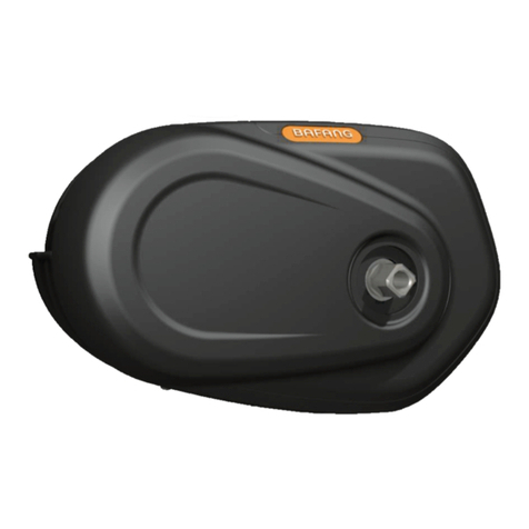
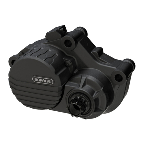
BAFANG MAX Drive System User manual

DEALER MANUAL
MAX Drive System
EN
Suzhou Bafang Electric Motor
Science-Technology Co., Ltd
No. 9 Heshun Rd
Suzhou Industrial Park
215122, Suzhou China
bf@szbaf.com
www.szbaf.com

DEALER MANUAL MAX DRIVE SYSTEM 2
CONTENT
Important Notice 4
For your Safety 5
6
1 Drive Unit (MM G33.250/350) 7
1.1 Advantages
7
1.2 Scope of Application 7
1.3 Product Naming Protocol 7
1.4 Main Techinialc Parameters 8
1.5 9
2 System Installation 10
2.1 10
2.2 11
2.3 Display Installation (DP C07.UART) 12
2.4 Auxiliary Keypad Installation 14
2.5 Battery Rail Installation 16
2.6 External Speed Sensor Installation (SR SD02.01) 17
2.7 Drive Unit Installation 20
3 System Cabling 27
3.1 Connection of the Battery Cable to the Drive unit 27
3.2 Connection of the Speed Sensor to the Drive unit 27
3.3 Connection of the EB-BUS to the Drive unti
28
3.4 Connection of the Headlight Cable to the Drive Unit
28
3.5 Connection of the Headlight to the Drive Unit 29
6 Display (DP C07.UART) 45
6.1 Specifications and Parameters of the Display 45
6.2 Appearance and Dimensions 45
6.3 Function Overview and Key Definations 46
6.4 Normal Operation
48
6.5 Parameter Setting 50
6.6 Error Code Definitions 55
7 List of Materials 56
7.1 Display Unit-DP C07.UART 56
7.2 Drive Unit -MM G33.250/350 56
7.3 Cables 58
8 Service and Warranty Policy 59
Notes 60
CONTENT
Note
Drive Unit Structure and Dimensions
List of Tools to be used
Component Names
5.4 Battery Health Indication 43
5.5 Battery Installation
44
5 Battery (Optional) 41
5.1 Using the Battery Properly 42
5.2 Charging the Battery 42
5.3 Battery Capacity Display 43
4 Chain Cover Installation
4.1 Installation of the Front Chainwheel............................. 30
4.2 Chain Cover Installation (optional)............................... 32
4.3 Crank Installation .........................................................39
30

41 DEALER MANUAL MAX DRIVE SYSTEM
5 BATTERY (BT CO1)
Precautions
•If any liquid leaking from the battery gets into your
eyes, rinse immediately with clean water (e.g. tap
water). Seek medical advice immediately; otherwise
the battery liquid may damage your eyes.
•Do not recharge the battery in places with high
humidity or outdoors. Doing so may result in
electric shock.
•Do not insert the plug while it is wet. Plug and
socket need to be dry, otherwise electric shocks
may result.
•If the battery does not become fully charged after
6 hours, unplug the battery from the outlet imme-
diately and stop charging. Not doing so may cause
overheating, rupture, or ignition of the battery.
•Do not use the battery if it has any noticeable
damage. Doing so may cause rupture, overheating
or malfunction.
•The battery may only be used in the temperature
ranges states below. Do not use the battery in
temperatures outside these ranges. If the battery
is used or stored in temperatures outside these
ranges, fire, injury or malfunction may occur.
•1. Temperature for discharging: –10℃to 50℃
•2. Temperature for charging: 0℃to 40℃
Danger
• Do not deform, modify or disassemble the battery.
Do not apply solder directly to the battery. Doing so
may cause leakage, overheating, rupture or ignition
of the battery.
• Do not leave the battery near sources of heat (e.g.
heaters). Do not heat the battery or throw it into a
fire. Doing so may cause rupture or ignition of the
battery.
• Do not subject the battery to strong shocks or th-
row it. If this is not observed, overheating, rupture
or ignition of the battery may occur.
• Do not immerse the battery into fresh water or
seawater, and do not allow the battery terminals to
get wet. Doing so may cause overheating, rupture
or ignition of the battery.
• Only use the specified charger. Not doing so may
cause overheating, bursting, or ignition of the bat-
tery. Observe the components during the specified
charging conditions when charging the battery.
• Do not short-circuit the discharge port with metal,
or else it may cause overheating, rupture or ignition
of the battery.
• Do not leave the battery in a place exposed to
direct sunlight, inside a vehicle on a hot day or in
other hot places. Doing so may result in battery
leakage.
• If any leaked fluid gets on your skin or clothes,
wash it off immediately with clean water. The
leaked fluid may damage your skin.
• Store the battery in a safe place out of the reach of
children and pets.
42
BATTERY (BT CO1)
DEALER MANUAL MAX DRIVE SYSTEM
5.1 Using the Battery
Properly
The battery can be charged at any time no
matter how much power is left. However, in
the following cases, the battery needs to be
fully charged. Make sure you use the specified
charger to charge the battery.
• The battery is usually not fully charged for the
convenience of transport. Make sure the battery is
fully charged before using the battery.
• If it is not intended to use the battery for a long
time, make sure the e-bike battery is charged
before storage and that is charged at least once
every twelve months thereafter. Do not leave the
battery completely discharged.
• Once you have begun to use the battery, please
have it charged at least once every two weeks.
If the battery is completely discharged,
charge it assoon as possible. If you do
not charge the battery, it will be da-
maged.
5.2 Charging the Battery
• When using the battery for the first time, check
that the battery has not run low in transport or
storage.
• If it not intended to use the battery for a long
time, charge the battery regularly to avoid excessi -
-
ve battery discharge.
• Please charge the battery as soon as possible
before it runs out; over-discharge can cause
permanent damage to the battery.
• No matter how much power is left, the battery
can be charged at any time. However, the speci
fied charger must be used to avoid overcharge of
the battery.
Display Light
Battery Level Display Switch

43 DEALER MANUAL MAX DRIVE SYSTEM
5.3 Battery Capacity
Display
Press the battery level display switch lightly. The
lights indicating the remaining battery
capacity will appear:
Battery Capacity
Display
Remaining Battery
Capacity
< 10%
11~30%
31~50%
51~70%
71~90%
91~100%
Light on
Light off
5.4 Battery Health
Indication
Press the battery level display switch for one
second. The battery health will be indicated
as follows:
Light on
Light off
Battery Health
Indication
Battery Health
Condition
< 40%
41~50%
51~60%
61~70%
71~80%
81~100%

44
BATTERY (BT C01)
DEALER MANUAL MAX DRIVE SYSTME
5.5 Battery Installation
A battery pack lock
B battery
Insert the battery pack from the tail of the carrier onto the rail. Push it to the front until you hear it snap into place in
the battery pack lock.
Please make sure the battery pack is locked to prevent the battery from becoming detached
while riding.

45 DEALER MANUAL MAX DRIVE SYSTEM
6 DISPLAY (DP C07.UART)
6.1 Specifications and Parameters of the Display
• 36V / 43V / 48V Power Supply;
• Rated Current: 10 mA
• Maximum Operating Current: 30 mA
• Power-off Leakage Current: <1uA
•Operating Current Supplied to the Controller: 50 mA
•Operation Temperature: -18 ~ 60 %
• Storage Temperature: -30~70 %
• Waterproof Grade: IP65
•Storage Humidity: 30 % – 70 %
6.2 Appearance and Dimensions
6.2.1 Materials and Dimensions
•The shell is made of PC. The liquid crystal display is made of hardened PMMA.

46
DISPLAY (DP CO7.UART)
DEALER MANUAL MAX DRIVE SYSTEM
6.3 Function Overview and Key Definitions
6.3.1 Function Overview
•Use of a two-way serial communication protocol,
simple operation of the display via the external
5-key keypad.
•Speed display: displaying the real-time speed as
SPEED, the maximum speed as MAXS and the
average speed as AVG.
•km or mile:The user can choose between km
and mile.
•Intelligent battery level indication: With an
optimization algorithm, a stable display of the
battery level is ensured, and the problem of fluc-
tuant battery level indication common with other
displays is avoided.
•Automatic light-sensitive lights: The headlight,
taillight and display light will be automatically
turned on/ off depending on lighting conditions.
•5 levels off display backlighting: Different levels
•5-Level-Support: setting power Levels 1 to 5
•Trip distance indication:The maximum distance
displayed is 99999. Single-trip distances TRIP or
the total distance TOTAL can be displayed.
•Display of error messages
•Walk assistance
•Settings: Various parameters, e.g. mode, wheel
diameter, speed limit etc., can be set on the com
puter via a communication cable. See the setting
•Maintenance warning (this function can be deac-
tived): Maintenance warning information is dis-
played based on battery charge cycles and riding
distance. The display automatically estimates the
battery life and gives warnings when the number
of charge cycles exceeds the set value. A warning
will also be displayed when the accumulated total
riding distance exceeds the set value.
6.3.2 Information on the Display
A Maintenance warning: When there is a need for
maintenance the symbol will be dis-
played (riding distance or the number of battery
charge cycles exceed the set value, function can
be deactivated)
B Menu
C Speed display: display of the speed, km/h or mph
D Speed mode: average speed (AVG km/h), maxi-
mum speed (MAXS km/h)
E Error display: When a fault is detected the
symbol will be displayed.
F Distance indication: display of the distance
depending on the setting.
G Level indication: The chosen level 1–5 will be
displayed; if there is no numeric display, it means
that there is no assistance (by the motor). If the
rider is walking and pushing the e-bike, will
be displayed.
H Walk assistance
I Headlight indication: only shows when headlight
or backlight are on

DEALER MANUAL MAX DRIVE SYSTEM
47
J Distance mode: display of the single-trip distance
TRIP and the total distance TOTAL
K Battery level: 10-segment battery indication; the
voltage that each segment represents can be
customized
6.3.3 Key Definitions
A up
B down
C headlight
D on/off
E mode

48
DISPLAY (DP C07.UART)
DEALER MANUAL MAX DRIVE SYSTEM
6.4 Normal Operation
6.4.1 O n/ Off Switch
Turn on the device. Press and hold for 2 seconds
to power on the display. Press and hold again for
2 seconds to power off the display. If the bike is not
used, after 5 minutes (time can be set) the display will
be automatically turned off.
6.4.2 Assist Mode Selection
In the manual gearshift mode, press the or
to choose the desired level of support by the motor.
The lowest level is Level 1, the highest Level 5. When
the display is on, the default mode is Level 1. When
there is no numeric mode display, there is no power
assistance.
Selecting the level for motor assistance
6.4.3 Switch between Distance Mode
and Speed Mode
to switch between distance and
speed. Single-trip distance ((TRIP km) total distance
(TOTAL km) maximum speed (MAXS km/h)
average riding speed (AVG km/h) are displayed in
successive order.
Switching between displays
Briefly press

DEALER MANUAL MAX DRIVE SYSTEM
49
6.4.4 Headlight/ Display Backlight
Switch
Press for 2 seconds. The backlight of the display
as well as the headlight and taillight will be turned
on. Press again for 2 seconds to power off the
display backlight/headlight/taillight. (If the display is
turned on in a dark environment, the display backlight/
headlight/taillight will be turned on automatically. If
the display backlight/headlight/taillight are turned off
manually, they also need to be turned on manually
afterwards).
Display backlight, headlight and taillight
There are 5 levels of backlight brightness that can be
selected by the user.
6.4.5 Walk Assistance
Press for 2 seconds. The e-bike enters the walk
assistance mode, and the symbol WALK is displayed.
Once the key is released, the e-bike will exit the
walk assistance mode.
Switch between power assistance and walk assistance mode

50
DISPLAY (DP C07.UART)
DEALER MANUAL MAX DRIVE SYSTEM
6.4.6 Battery Status Indication
When the battery status is normal, a certain number of the battery LCD segments as well as the border light up
according to the actual quantity of charge. If all of the 10 segments will black out with the border blinking, the
battery needs to be charged immediately.
Battery status indication
Number of
Segments
Charge in
Percentage
Number of
Segments
Charge in
Percentage
Number of
Segments
Charge in
Percentage
10
9
8
7
6.5 Parameter Setting
6.5.1 Items to be Set:
1 Data reset
2 km/mile
3 Light sensitivity
4 Display backlight brightness
5 Automatic off time
6 Maintenance warning settings
7 Input of the password
8 Wheel diameter selection
9 Setting speed limit
≥90 % 6 50 % ≤C < 60 % 2 15 % ≤C < 25 %
60 % ≤C < 70 % 3 25 % ≤C < 35 %
80 % ≤C < 90 % 5 45 % ≤C < 50 % 1 5 % ≤C < 15 %
70 % ≤C < 80 % 4 35 % ≤C < 45 % border blinking C < 5 %

DEALER MANUAL MAX DRIVE SYSTEM
6.5.2 Setting Preparation
When the display is active, press twice (interval
< 0.3 seconds). he system will enter the ME -
rameter setting state, in which the display parameters
can be set. Press twice again (interval < 0.3
seconds) to return to the main menu.
Menu for entering the parameter settings
In the parameter setting state, when the parameter you
want to set begins to flash, press / to adjust the
parameter value. Briefly press to switch between
the parameters to be set. Press twice (interval
< 0.3 seconds) to exit the submenu.
If no operation is performed for 10 seconds, the display
will return to the normal riding display.
6.5.3 Data Reset
Press twice (interval < 0.3 seconds) – the display
enters the MENUstate. In the speed field tC is dis -
played. If you press , a y is also displayed.
temporary data, e.g. maximum speed (MAXS), average
speed (AVG) and single-trip distance ( TRIP) can be
cleared. Briefly press (< 0.3 seconds) to enter the
km/mile setting interface.
If the user does not reset the data, the single trip
distance and the accumulated total riding time will
be automatically cleared when the accumulated total
riding time exceeds 99 hours and 59 minutes.
The data will not be cleared when the display’s light-
sensing function is set to 0 or when it is switched off.
6.5.4 km/mile
When the speed field displays S7, press / to
switch between km/h and mph, or to set km or mile.
After this setting, briefly press (< 0.3 seconds) to
enter the setting interface of light sensitivity.
51

52
DISPLAY (DP CO7.UART)
DEALER MANUAL MAX DRIVE SYSTEM
6.5.5 Light Sensitivity
When the speed field displays bL0, use /
to choose a figure between 0 and 5. The higher the
chosen figure, the higher the light sensitivity.
After this setting, briefly press (< 0.3 seconds) to
enter the setting interface of backlight brightness.
6.5.6 Display Backlight Brightness
When the speed field displays bL1, press
/
to choose a figure between 1 and 5. The figure 1
represents the lowest brightness while 5 indicates the
highest display backlight brightness.
After this setting, briey press (< 0.3 seconds) to
enter the setting interface of automatic off time.

53 DEALER MANUAL MAX DRIVE SYSTEM
6.5.7 Automatic Off Time
When the speed field displays OFF, press / to
choose a figure between 1 and 9. The gures indicate
the minutes that it takes to automatically shut down
the display.
After this setting, briefly press (< 0.3 seconds) to
enter the setting interface of maintenance warning.
6.5.8 Maintenance Warning
(can be deactivated)
When the speed field displays nnA, press / to
choose either 0 or 1. 0 disables the function while 1
enables it.
After this setting, briefly press (< 0.3 seconds) to
enter the setting interface of password input.
Maintenance Warning Setting
The display will prompt maintenance necessity based
on such information as the accumulated riding dis
-
tance and the battery charge cycles.
• When the accumulated total riding distance
exceeds 5,000 km (can be customized by the
manufacturer), the display will show the symbol
. When the display is started up, the
sign for accumulated riding distance will flash
for 4 seconds, indicating that maintenance is
necessary.
• When the number of battery charge cycles ex
-
ceeds 100 (can be customized by the manufactu-
rer), the display will the symbol . When
the display is started up, the sign for battery will

54
DISPALY (DP CO7.UART)
DEALER MANUAL MAX DRVIE SYSTEM
flash for 4 seconds, indicating that maintenance
is necessary.
•The maintenance alert function can be disabled:
settings maintenance alert (MA) main-
tenance alert (MA) 0. (Maintenance alert
can also be set via a computer.This requires a
USB connection. See also the parameter setting
instructions).

55 DEALER MANULA MAX DRIVE SYSTEM
6.6 Error Code Definitions
The MAX-C966 display can show e-bike faults. When a fault is detected, the icon will be displayed. In the speed
field one of the following error codes will be displayed:
Error Code Error Description Error-shooting Method
“03” Brake enabled Check whether a brake cable is stuck
“04” The throttle has not returned home Check if throttle has returned home
“05” Throttle fault Check the throttle
“06” Low voltage protection Check the battery voltage
“07” Overvoltage protection Check the battery voltage
“08” Motor hall signal cable fault Check the motor module
“11” Controller temperature sensor failure Check the controller
“12” Current sensor failure Check the controller
“13” Battery temperature fault Check the battery
“21” Speed sensor fault Check installation position of speed sensor
“22” BMS communication fault Replace the battery
“30” Communication fault Check the controller connection
Error display
“10” Stop the bicycle until the error code “10”
disappears from the screen
Note: Error Code 10 will probably appear on the dispaly
when the e-bike is climbling for a long time. This indicates
that the motor temperature has reached the protection
value, in which case the user needs to stop the e-bike for a
rest. If the user continues to run the e-bike, the motor will
automatically cut off the power.
The motor temperature has reached
the threshold
Other manuals for MAX Drive System
1
Table of contents
Other BAFANG Engine manuals

BAFANG
BAFANG H600 User manual

BAFANG
BAFANG MM G333.250.C User manual

BAFANG
BAFANG M420 User manual

BAFANG
BAFANG M420 User manual

BAFANG
BAFANG H610 User manual

BAFANG
BAFANG H550 User manual

BAFANG
BAFANG FM G320.250.R User manual

BAFANG
BAFANG H620 User manual

BAFANG
BAFANG H400 User manual

BAFANG
BAFANG RM G370.250.DC User manual
Popular Engine manuals by other brands

Moons'
Moons' TSM34P-1AG Hardware manual

Saito
Saito FG-33R3 instruction manual

Briggs & Stratton
Briggs & Stratton PowerBuilt Snow 120000 Series Operating & maintenance instructions

Ruggerini
Ruggerini RY 125 Use & maintenance

MW Fly
MW Fly B22 AeroPower Quick installation

ELTE
ELTE TMA 5 14/2 operating manual