4 Setup
Connect the power cord to an outlet of the appropriate voltage.
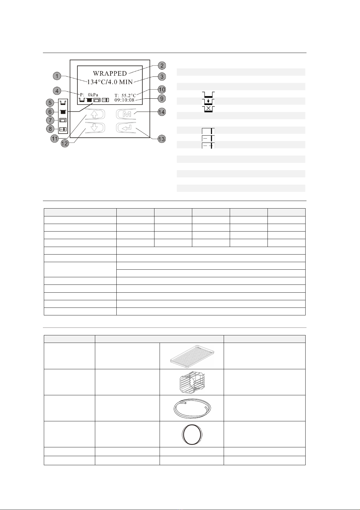
Turn on the main power switch on the right side. Open the door to remove all of the inner contents for
unpacking. After switching on, the machine turns on the LCD and shows the door position, water level,
working program, date, time, etc.
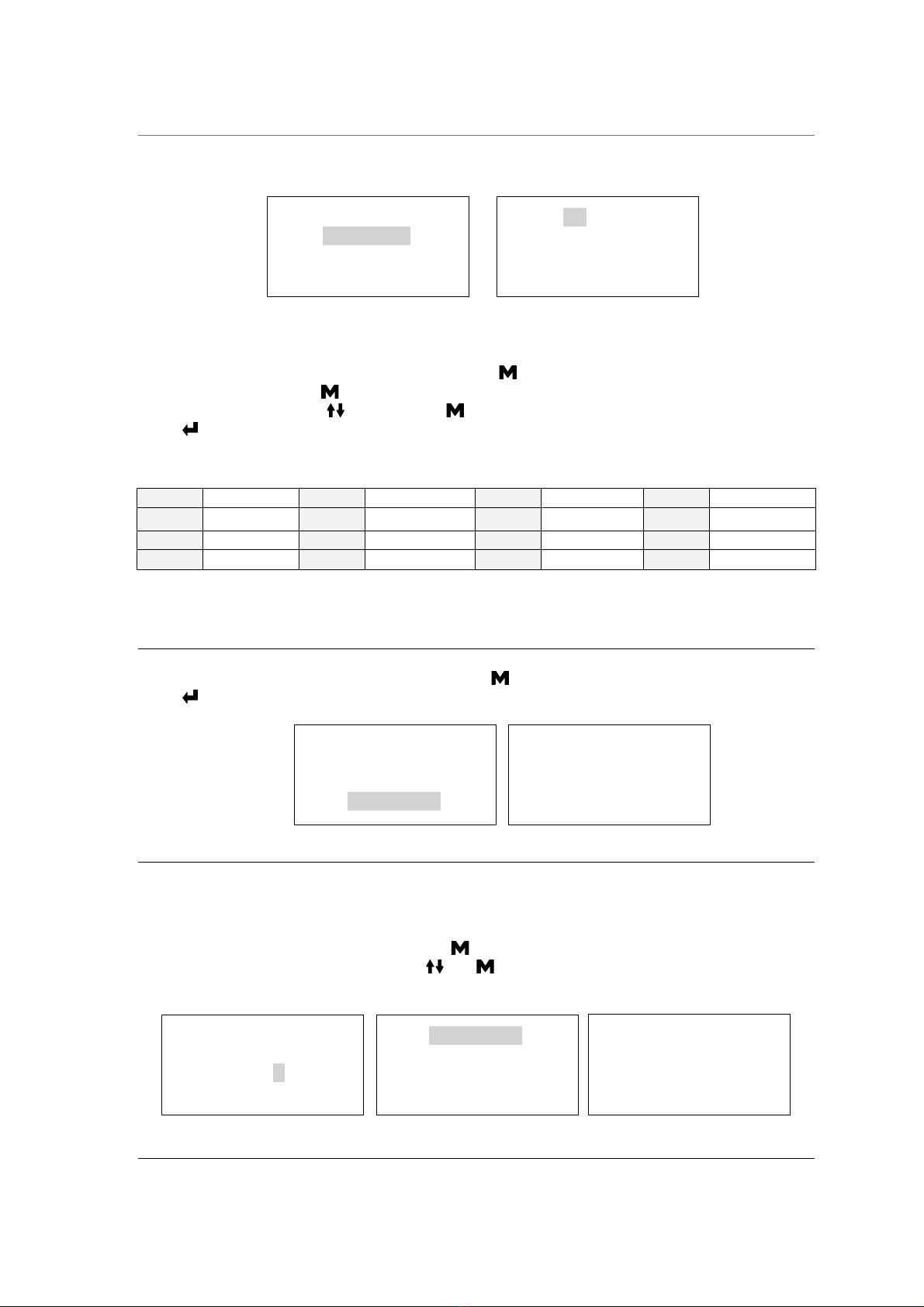
Fill the distilled water tank
Manual water filling
When the level of distilled water reaches a minimum level, the distilled water tank icon will flash and beep
three times.
Press the button on the tank lid and open it to the maximum position.
Fill it carefully with distilled water.
If exceeds the maximum level, an alarm will sound, and the distilled water tank icon will blink.
Drain the used water tank
Attach the drain hose on the drain connector located inside the service
door at the left.
Attention: The capacity of the used water tank is approximately 1.5 liters
Preparation of sterilization materials
For the most effective sterilization and to preserve the sample, please follow below:
§ Clean instruments immediately after used.
§ Treat the instruments by ultrasound cleaner.
§ Residual chemicals left over after cleaning and disinfecting process may damage and corrode
parts of the sterilizer, always rinse off the instruments using distilled water.
§ Follow instrument manufacturer’s guidelines and recommendations for handing and cleaning
instruments prior to sterilization.
§ Check the manufacturer’s instructions as to proper procedure for sterilizing of each item.
§ Arrange the samples of different materials on different trays or with at least 3cm of space
between them.
§ Clean and dry instruments thoroughly before placing them into tray.
§ Always insert a sterilization paper or cloth between the tray and sample to avoid direct contact.
§ Arrange the containers (glasses, cups, test-tubes, etc.) on one side or inverted position,
avoiding possible water stagnation.
§ Don’t stack the trays one above the other or put them in direct contact with the walls of the
sterilization chamber.
§ Always use the instrument tray handle.
§ Wrap the samples one by one or, if more tools have to be set in the same bag, verify that these
are made of the same material.
§ Don’t use metallic clips, pins or other, as this jeopardizes the maintenance of the sterilizer.
§ Don’t overload the trays over the stated limit (see appendix 2).