Baker SterilGARD II SG400STD User manual

-~
ARTISAN
®
~I
TECHNOLOGY
GROUP
Your definitive source
for
quality
pre-owned
equipment.
Artisan Technology
Group
Full-service,
independent
repair
center
with
experienced
engineers
and
technicians
on staff.
We
buy
your
excess,
underutilized,
and
idle
equipment
along
with
credit
for
buybacks
and
trade-ins
.
Custom
engineering
so
your
equipment
works
exactly as
you
specify.
•
Critical
and
expedited
services
•
Leasing
/
Rentals/
Demos
• In
stock/
Ready-to-ship
•
!TAR-certified
secure
asset
solutions
Expert
team
ITrust
guarantee
I
100%
satisfaction
All
tr
ademarks,
br
a
nd
names, a
nd
br
a
nd
s a
pp
earing here
in
are
th
e property of
th
e
ir
r
es
pecti
ve
ow
ner
s.
Find the Baker Company SterilGARD VBM-600 at our website: Click HERE

OPER~~TOR'S
MANUAL
Baker
SterilGARD
®II
Biological
Safety
Cabinet
MODELS
SG400STD,
SG600STD
,
SG400ULT, SG600ULT
THE BAKER COMPANY
NSF
classification: Class II, Type A.
(When
the
unit
is
vented
to the
outside,
the classification
is
Class II,
Type
B3).
This
manu
al
includes
information
for
installation,
op
eration,
maintenance
and
sp
are
parts.
We
recommend
that
it
be
kept
near
the
cabinet
for
ready
reference.
No
v
ember
, 1998
Revised: 10-2009

THE BAKER COMPANY
INTRODUCTION
AND
WELCOME
It
is a
pleasure
to welcome
you
to the
growing
number
of customers
who
own
and
operate
Baker biological safety cabinets.
As
the
inventors
of
the
laminar
flow biological safety cabinet
and
the
leaders
in
the
field, Baker
people
take
special
pride
in
providing
a cabinet
which
is
designed
for
maximum
performance.
Your
new
SterilGARD®ll
has
a
number
of
remarkable
features.
Among
them, the
contaminated
positive
pressure
areas,
which
include the
work
area, are
surrounded
by
a
negative
pressure
plenum.
Tilis
arrangement
provides
an
extra
measure
of protection
because
any
particle
in
the
contaminated
zone
will invariably be
drawn
through
the
blower
and
trapped
on
a filter.
You
will
find
your
SterilGARD®II cabinet suitable for use not only
with
l.V.
drug
preparations
and
other
pharmaceuticals,
which
could
have
adverse
health
effects
on
operators,
but
also for clinical diagnostic
work
involving tissue
culturing
of possibly infectious
samples
and
other
techniques requiring a contamination-free ahnosphere.
Please
note
that
all open-front
containment
cabinets, including this one, are for
use
with
low
to
moderate
risk
agents only. Open-front cabinets
do
not
provide
absolute protection for
the
user.
The
adequacy
of a cabinet for
user
safety
should
be
determined on-site
by
an
industrial
hygienist,
safety officer
or
other
qualified
person.
Remember
that
you,
the
owner
and
user,
are
ultimately
responsible
and
that
you
use
your
cabinet at
your
own
risk.
Built
to
exceed all microbiological aerosol tests specified
by
applicable NSF
standards,
your
SteriJGARD"'l!
unit
includes
many
unusual
Baker features
which
are included for
superior
performance,
simpler
maintenance
and
lower
life cycle cost. Your SterilGARD8
II
mut
.is
designed
for
both
safety
and
value.
We
recommend
this manual, along
with
the
factory test
report
that
is included,
be
kept
near
the
cabinet
for convenient reference
by
operators
and
qualified
maintenance
personnel. If
you
have
any
questions
about
the
use
or
care of
your
new
SterilGARD"'ll cabinet, please
do
not
hesitate
to
contact
our
Customer
Service
Department
for assistance.
SiHcerely,
Dennis
Eagleson
President
The
Baker
Company,
Inc.
P.O.
Drawer
E,
Sanford, Muine 04073 (207) 324-87731-800-992-2537
FAX
(207) 324-3869
"Creating
immaculate
atmo.rpheres"
1

TABLE
OF
CONTENTS
IN1RODUCTION
........................................................................................................
Page
i
I
FUNCTION
AT\JD
DESCRIPTION
OF
THE
STERILGA.t~D'II
CABINET................... 1
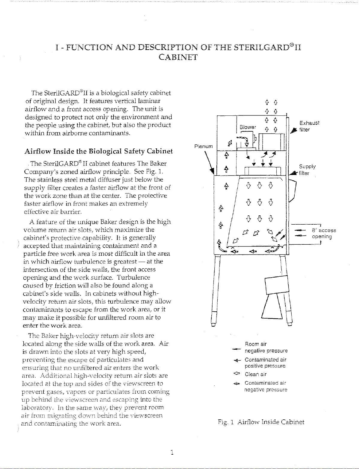
Airflow
Inside
the Biological Safety
Cabinet
................................................................. 1
Positive
and
Negative
Pressure
Areas
........................................................................... 2
Access to the
Work
Area
................................................................................................. 2
Design
Details
................................................................................................................... 2
S
"f"
.
.1
peG
1cahons
....................................................................................................................
~
II
PREPARING
THE
STERILGARD®II CABINET FOR USE .....
...
..
.......
...
.................... 5
Checking
the
Cabinet
on
Arrival
..................................................................................... 5
The
Uses
of a Biological Safety
Cabinet
......................................................................... 5
Cautions
............................................................................................................................ 5
Location
Within
the
Laboratory
...................................................................................... 5
Installing
the
Cabinet
....................................................................................................... 6
Assembling
the
Footrest
.................................................................................................. 7
Connecting
the
Exhaust
................................................................................................... 9
Final
Connections
and
Tests ............................................................................................ 9
III
PROPER
CABINET USE ................................................................................................
11
Operator
Controls
..........................................................................................................
11
Air
Pressure
Monitor
/Magnehelic
Gauge
................................................................... 12
Ground
Fault
Interrupter
.............................................................................................. 13
Start-up
Procedure
......................................................................................................... 13
Working
in
the
Cabinet
Work
Space ............................................................................ 13
Reacting
to Spills ............................................................................................................ 14
Ultraviolet
(Germicidal)
Light
......................................................................................
15
Decontamination
............................................................................................................
15
Using
Ancillary
Equipment
.......................................................................................... 17
About
the
HEPA
Filters ................................................................................................. 17
Operating
Procedures
.................................................................................................... 18
IV ON-SITE CHECKS
AND
MAIN"TENAl\JCE ............................................................... 19
The
Airflow
Balance ...................................................................................................... 19
Filter
Media
and
Seal Leak Tests .................................................................................. 20
Airflow
Smoke
Pattern
Test .......................................................................................... 20
Cabinet
Integrity
Test .................................................................................................... 20
G ,
d.
r f
··t
~-
·t "1
roun
mg
~on
rnm
y l es .
..
.
..
...........
..
.
..
....
..
...
..
..........
..
.
....
....
..
...
..
...........
..
.
..
.....
..
....
..
.
~
fv1aintenance
?-.Jotes
.........................................................................................................
::?.1
Replacing
the
HEP
A Fil ten; ...........................................................................................
21
Trc,1Jbleshc)oti11g .............................................................................................................
23
ll

APPENDIX ...................................................................................................................
Page
26
Wiring
Diagram, SG400 Models ................................................................................... 26
Wiring
Diagram, SG600 Models.................................................................................... 27
Dimensional
Drawing,
Model SG400STD ................................................................... 28
Dimensional
Drawing,
Model SG600STD .............................................;......................
29
Dimensional
Drawing,
Model SG400ULT.................................................................... 30
Dimensional
Drawing,
Model SG600ULT ...................................................................
31
Replacement
Parts
List, Models SG400STD & SG600STD .......................................... 32
Replacement
Parts
List, Models SG400ULT & SG600ULT...........................................
33
Warranty
..........................................................................................................................
34
LIST OF FIGURES
Fig. 1 Airflow
Inside
Cabinet .............................................................................................. 1
Fig. 2
Adjusting
the Telescoping Leg Assembly ................................................................ 6
Fig. 3 Installation
Without
Lifting
Equipment
................................................................... 6
Fig. 4
Assembling
the Footrest ............................................................................................ 8
Fig. 5
Operator
Controls .....................................................................................................
11
111

I
-FUNCTION
AND
DESCRIPTION
OF
THE
STERILGARD®II
CABINET
The
SterilGARD"'II is a biological
safety
cabinet
of
original
design.
It
features
vertical
laminar
airflow
and
a
front
access
opening.
The
ru1it is
designed
to
protect
not
only
the
environment
and
the
people
using
the
cabinet,
but
also
the
product
within
from
airborne
contaminants.
Airflow
Inside
the
Biological
Safety
Cabinet
The
SterilGARD® II cabinet
features
The
Baker
Company's
zoned
airflow
principle. See Fig. 1.
The
stainless
steel
metal
diffuser
just
below
the
supply
filter creates a faster airflow
at
the
front
of
the
work
zone
than
at
the
center.
The
protective
faster
airflow
in
front
makes
an
extremely
effective
air
barrier.
A
feature
of
the
unique
Baker
design
is the
high
volume
return
air slots,
which
maximize
the
cabinet's
protective
capability.
It
is generally
accepted
that
maintaining
containment
and
a
particle
free
work
area
is
most
difficult
in
the
area
in
whim
airflow
turbulence
is
greatest-
at
the
intersection
of
the
side
walls,
the
front
access
opening
and
the
work
surface.
Turbulence
caused
by
friction will
also
be
found
along
a
cabinet's
side
walls. ln cabinets
without
high-
velocity
return
air slots, this
turbulence
may
allow
contaminants
to
escape
from
the
work
area,
or
it
may
make
it
possible
for unfiltered
room
air
to
enter
the
work
area.
The
Baker
high-velocity
retu.m
air
slots are
located
along
the
side
walls
of
the
work
area.
Air
is dravv:n
into
the
slots
at
very
high
speed,
preventing
the
escape
of
particulates
and
ensuring
that
no
unfiltered
air
enters
the
work
area.
Additional
hjgh-velocity
return
air
slots
are
located
at
the
top
and
sides
of
the
viewscreen to
prevent
gases, \'·apors
or
particulates
from
con1ing
up
behlnd
the
vie\vscreen
and
escaping
into
the
laboratory.
In
the
same
\va.L they'
prevent
room
air
.frorn
do>A'T1
behJnd tl1e \/ie'i\rscreen
and
contarninatLTlg
the
work
area.
1
P!enum
~
~
<}
t
;;J
-
Blower
v v v
v v v
t::J;;J
-
Room air
negative pressure
+ Contaminated air
positive pressure
<>
Clean air
.qp.
Contamina~ed
air
negative pressure
Exhaust
)I>
filter
Supply
filter
~
8"
access
----
opening
Fig. 1 Airflow Inside
Cabinet

Positive
and
Negative
Pressure
~<\reas
One
of the n1any features
that
sets the
SterilGARD"':-n
unit
apart
frorn
oL~er
cabinets
is
the
interaction
of
positive
cu1cl
negative
pressure
areas.
The
srrtalJ
posibve
pressure
pienwn
is
cornpleteJy
surrollnded
by a negati'i/e
pressure
area
so
that
any
partide
passing
through
is
invariably
drawn
thrm1gh the
blower
and
trapped
in a filter.
From
the
small
positive
pressure
plenum,
which
is
shown
.in
Figure
1,
about
30
percent
of
Ll-te
total
cabinet
airflow
is
expelled
through
the
exhaust
filter.
The
remaining
70
percent
is
recirculated
through
the
supply
filter
and
re-enters
the
work
area
as
particle-free
air. Because
the
cabinet
must
take
in
air
to
replace
the
air
expelled
through
the
exhaust
filter,
the
same
volume
of
room
air
enters
the
cabinet
through
the
8-inch front access
opening.
This
air,
which
never
enters
the
work
area,
cornp
letes
the
air bar.rier
at
the front access
opening.
All
air
is
combined
under
the
work
surface.
From
here,
the
contaminated
air
is
pulled,
under
negative
pressure,
through
a
plenurn
up
the
rear
of
the
cabinet
into
the
motor-blower,
which
blows
it
into
a
positive
pressure
plenum.
Please
note
again
that
the
positive
pressure
plenum
is
completely
surrounded
by
negative
pressure
areas.
If
a
leak
should
occur in a
contaminated
negative
pressure
plenum,
or
in the
side
wall
or
rear
wall,
the
negative
pressure
will create
suction
and
pu
!I
air
in,
not
allowing
it to
escape
into
the
operator's
area.
If
there
is
a leak
from
the
positive
pressure
plenum,
the
surrounding
negative
pressure
area
will
recapture
the contamicnated
air
and
recirculate
it
through
a filter.
Access
to
the
Work
Area
For
easy
entry
of
apparatus
into
the
work
area,
SterilGARD"'ll
has
a vertical sliding
viewscreen
.
..
Its \4-inch
safety
plate
glass
allows excellent
visibility
and
may
be
opened
to a
height
of
18
W'
to
permit
placement
of
items
in the
work
area.
TI1e
window
should
be
set
at
a
height
of 8"
while
work
is
being
performed,
and
an
alarm
is
provided
to
remind
the
operator
if
the
window
is
not
in
the
correct
position
for
using
th.e cabinet.
(Chapter
3
on
"Proper
Cabinet
Use'' will
explain
ho\v to
use
the
·v-ieTNscreen
correctly vvlli]e
the
cabinet
is
in use.)
As
with
other
Baker cabinets,
the
electricctl
outlets
Lnside
the
\Vork.
area
have a
circuit
bre::tker
so
that
an
electrical
overload
by
ancillary
equipment
will
not
affect air
handling.
Overloading
with
electrical
equipment
should,
of
course, be avoid.ed in any case. (See th.e
"A.ncillary
Equipment"
instructions
in
Chapter
3
on
"Proper
Cabinet
Use",
and
in
the
"Appendix.")
Design
Details
Performance
assurance
Meticulous
care
in
manufacturing
is
followed
by
more
than
14
separate
performance
tests
prior
to
shipment
of
your
cabinet.
In
addition,
a
complete
factory test
report
on
the
performance
of
your
unit
is
included
at
the
back
of
this
manual.
Motor/
blower
capacity
A
motor/blower's
capacity
is
measured
by
its
ability
to
provide
a
nearly
constant
volume
of
air
as resistance increases becau.se
of
filter
loading.
Verification
by
a
simulated
filter
loading
test
has
established
that
your
SteriiCARD"Il
cabinet
is
capable
of
auto~atically
handling
an
80% (in
both
4-foot
and
6-foot 1mit) increase in
pressure
drop
across
the
filter
without
reducing
total
air
delivery
more
than
10~/o.
A
convenient
magnehelic
gauge
(or
bar
graph
display
on
the
ULTRA
models)
shows
the
current
relative
performance
of
the
blower.
With
the
use
of
the
manual
speed
control,
a 165');,/180% (4-foot/6-foot unit)
increase
in
the
pressure
drop
across
the
filter
can
be
handled.
The
resulting
long
filter life
means
significant
cost
savings.
One-piece
interior
wall
construction
The
interior
side
and
rear
walls
of
your
Steri!GARD®Il's
work
area
are
constructed
from
a
single piece
of
16-gauge
stainless steel.
The
easy-
to-clean 7
/16-inch
radiused
(rounded)
comers
prevent
buildup
of
contaminants
and
resist
corrosion.
Protective
screen
Located
under
the
work
surface
at
the
bottom
and
sides of the
rear
return-air
plenum,
a

protective
screen
is
provided
to
help
prevent
wipes
and
other
paper
materials
from
being
drawn
into
the
blower
system.
This
precaution
eliminates
costly
decontamination
and
downtime.
The
screen
affords
easy
access to
waste
materials
and
should
be
kept
clean
at
all times.
All-metal
plenums
The
plenums
of
your
SterilGARD"II
unit
have
been
constructed
entirely
of
metal
in
order
to
provide
strength,
durability,
air-tightness
and
resistance
to
deterioration.
Recessed
stainless
steel
work
surface
The
work
surface
is
constructed
of
corrosion-
resistant
16-gauge
type
304 stainless steel. Its
satin
finish
diminishes
light
reflection.
It
is
recessed
to
retain
spills,
and
the
3/16"
radiused
con1ers
make
for
easy
cleaning.
Cabinet
exterior
Extemal
construction
is
of
14-gauge
cold-rolled
steel,
protected
by
a
smooth
white
baked
enamel
finish.
Tested
HEPA!ULPA
filters
Supply
and
exhaust
filters
in
SterilGARDeii
are
zero-probed
HEPA.
They
have
been
found
to
be
99.99% effective
on
particles
of
0.3
micron
size.
In
the
SterilGARD''II
ULTRA 4-foot
model
only,
supply
and
exhaust
ULPA
filters are
used,
whicll
are
99.999'Yo
effective
on
particulates
of
0.12
micron.
Eacll filter is
scan-tested
to
assure
leak-
free
installation.
Viewscreen
The
cabinet's
%-incll safety
plate
glass
vertical
sliding
viewscreen
may
be
opened
to
18
Yz"
for
placement
of
large
items
in
the
work
area,
and
may
be
fully
closed
for
system
shutdown.
Drain
valve
MeetL"1g
NSf
requirements
for
drainage
in
Class
II
biologicaJ
safety
cabh"'"tets,
a
stainless
stee]
baJJ
>.raJve
i_n
the
SterJJGARD~]l
unit
is installed for
sc:Je
effective d.rainage
of
the
drain
pan.
Work
area
lighting
SterilGARD"'II's
lighting
system
produces
100
to
150 foot candles
of
illumination
at
the
work
surface
area. The fluorescent tight
is
extemall.y
m01mted to
minimize
heat
buildup.
The
unit
uses
two
common
fluorescent bulbs.
Air
balance
adjustments
Air
balancing
can
be
done
by
either
of
the
following
methods.
It
should,
however,
be
done
only
by
a teclmician
with
proper
training
and
equipment.
(See Section 4, "On-Site
Checks
and
Maintenance
Procedures.")
• A
speed
controller
adjusts
for
voltage
differences
and
filter loading.
•
An
adjustable
damper
compensates
for
differences
of
supply
and
exhaust
filters if
they
are
changed
at
a later
date.
Easy
filter
access
For convenience
and
ease
of
service,
the
supply
and
exhaust
filters
are
loaded
and
removed
from
the
front
of the
cabinet
without
entry
into
SterilGARD'''Il's
work
area. This
is
particularly
helpful
if the cabinet is
connected
to
an
exhaust
duct. Filters
should
be
replaced
by
qualified
technicians on!
y.
Stainless
steel
telescoping
leg
assembly
TI1e
Steri!GARD"II
unit
has
a
distinctive
assembly
with
four
telescoping
legs,
whicll
allows
the
cabinet to
be
shipped
with
a
minimum
height
of
74
7/8".
The
assembly
also
makes
it
possible
to
adjust
the
cabinet
to
two
heights,
providing
a
work
surface of
either
30"
or
36"
above
the
floor.
Leg I Knee
Work
Exten- Space
Surface
Overall
sion
I
Height
Height
Height
Shipping &
11~~./-,;
" I < 74
cIs"
--I
fnstallation I I
Setting A i
25'"
) 26''* I
30'''!"
I
891/o"
i
'
'
~
/
Settmg
B
'I
.,
'
0"
••
1
..
)
""!
• !
/~:;,
:/
b !
levelerc;

Specifications
Weight
The
weight
of the SterilGARD'"II 4-foot cabinet
is
630
pounds
with
a shippirtg weight of
875
lbs.
A 6-foot cabinet weighs
840
pounds
with
a
shipping
weight
of
1075
pounds.
Electrical
specifications
115V
AC,
1 Phase,
60
Hz
The SterilGARD0
11
incorporates a solid-state
controller for
the
blower motor. This compensates
for variations
in
incoming line voltages. The
usable
voltage
range
is
95
to
130V
AC
The
unit
is
provided
with
two duplex G.FJ.
receptacles
at
a total of 5.0 amps, controlled
by
an
internal
self-resetting circuit breaker. The
unit
is
furnished
with
one
12'
power
cord with 20-amp
plug,
type
NEMA
5-20P.
Blower
motor
(1
,625 RPM)
Fluorescent Light (ballast)
Duplex
outlets (G.F.!.)
Total
running
load
SG400/SG600
6.6
amps/9.9
amps
0.7
amps/0.7
amps
5.0
amps/5.0
amps
12.3
arnps/15.6
amps
4

II
-
PREPARING
THE
STERILGARD®II
CABINET
FOR
USE
Checking
the
Cabinet
On
Arrival
Upon
receipt
of
your
new
SteriiGARDoll
cabinet,
first
inspect
the
exterior
of
the
crate
and
skid.
If
there
is
any
broken
glass
or
other
visible
damage,
that
fact
should
be
noted
on
the
receiving
slip
and
immediately
reported
to
the
delivering
carrier.
Now
remove
the
crate
and
inspect
the
tmit
itself.
The
top
cover
of
the
crate
should
be
taken
off first,
then
the
boards
from
front
and
back.
Bend
both
ends
of
the
crate
outward
away
from
the
sides
of
the
unit
and
remove
front
or
rear
blocking
from
the
skid.
Remove
the
cabinet
from
the
skid
with
a
fork
lift
or
other
available
equipment.
If
any
concealed
damage
is
found
it
should
be
reported
to
the
delivering
carrier,
who
will
want
m1
opportunity
to
inspect
the
damage.
A
claim
for
restihttion
shollld
be
filed
within
15
days.
.
Because
of
the
dwger
of
mishandling
by
trucking
companies,
we
have
removed
certain
parts
of
the
cabinet
and
have
packed
them
separatelv.
These
items
are
listed
on
the
packing
slip
which
accompanies
the
unit.
Please
check
the
packing
slip
carefully
to
be
sure
that
all
items
have
been
located.
The
Uses
of
a
Biological
Safety
Cabinet
The
SterilGARD"II
cabinet
has
been
designed
to
provide
a
work
area
which
protects
the
experiment
from
the
environment,
and
the
enviroruncnt
frorn
the
experi-ment. The
larninnr
flow biological
safety
cabinet
is
designed
for
work
with
Biosafety Levels 1, 2
and
3 (low
to
moderate
risk)
agents
as
listed
in
The
Center
for
Disease
Control's
~~Biosafety
in
lviicTobiological
and
Biomedical
Laboratories",
U.S.
Department
of
Health
and
Hllman
Services, Public I-Iealth
Service,
Centers
for
Disease
Control
and
National
Institutes
of
Health,
L.S.
Govenunent
Printing
Office,
Washington,
D.C. 20402.
HHS
publication
nurnber
(CDC! 34.-3395.
Biosafety
level
4
or
extremely
f'Ligh
risk
agents
sl1ould neve·r
be
used
in
ul-lls
cabinet. Please
5
consult
your
safety
professional
for a
proper
risk
assessment.
C4.UTIONS
*
T1w
use
of
any
hazardous
material
in the
cabinet requires
that
it
be
monitored
by
an
industrial
hygienist,
safety
officer or
other
qualified i>u/ividual.
* Explosive or flammable su/Jstances
should
never be used in the cabinet
unless
a quali-
fied
safety
professional
has
evaluated
the
risk.
*
lf
hazardous biological
work
is
to
be
per-
formed,
apply
the app1·opriate
biohazard
de-
cal which is enclosed. This is in accord
with
OSHA
regulations, volume 39,
11umber
125,
PadiL
*
If
chentical, 1·adialogical
or
other
n.on.micro-
bialogical hazards are present,
be
sure
to
employ
appropriate protective measures in
addition
to
formaldehyde decontamination.
Call upol! a
suitably
trailred
individual
to
monitor
the operation.
Location
Within
the
Laboratory
The
ideal
location for
any
laminar
flow
biological safety cabinet is
in
a
dead-end
comer
of
the
laboratory
away
from
personnel
traffic,
vents,
doors,
windows
and any
other
sources
of
dismptive
air
currents.
Published
research
from
The
Baker
Companv
(Rake, B.W.
"Influence
of
Crossdrafts"
on
the
Perfonnance
of
a Biological
Safety Cabinet. Appl. Microbiology 36:278-283,
1978.)
and
w1published tests
performed
at
the
National
Cancer
Institute
show
that
i.f
a
draft
or
other
disruptive
air
current
were
to
exceed
the
intake
velocity
of
the
cabinet,
then
contarrlination
can e-nter
the
vvork
area
or
escape
frorn
it.
Proper
placement
within
the
is
essential.
If
the
cabinet
exhausts
Lts
air
into
the
Iaborrltonr
ins:tead of
venting
to the OL.ltsidef
it
is
imoortant
that
there
be
adequate
space
between
th~
top
of
t._he
cabinet
and
the
ceiling. A soJjd ceiling
located

too close to the exllaust filter
vvill
restrJct the air
and
limit
the
intake
velocity..
t.,
mi_ni.mum
of
12"
of
clearance
on
all
sides
and
top
of
the cabinet
is
necessary
to
achieve
ideal conditions for testing.
If
a free
space
of
12"
above the
exhaust
filter
is
not
available, inaccuracies in
exhaust
flow
measurements
mav
result.
Consult
with
our
Customer
Service
Department
for
the
implications
of
this,
and
for alternatives.
Installing
the
Cabinet
Installation
of
this
cabinet
should
be
carried
out
in
accordance
with
appropriate
OSHA
regulations
and
those
of
other
regulatory
agencies
having
jurisdiction.
1. First,
move
the
cabinet
from the
unloading
area
to
its
intended
location
on
dollies. The
overall
dimensions
in
the
shipping
position
for
the
·!-foot
unit
are: 34 :I
12"
deep
x 53 3I 16"
wide
x 74 7
Is"
high. For the 6-foot unit,
the
overall
shipping
dimensions
are: 34 1
/32"
deep
x 77
'/1s"
wide
x 74 7
Is"
high.
Glass
window
) /
(tron1
of
oabine1)
Work
surface
opening
lower
edge
Fig. 2
Adjusting
the
Telescoping
Leg
Assembly
6
~
0 J.l
\
CJ
0
vlegbolt
\\
-'-
,,
8" lift
•
Fig. 3 Installation
Without
Lifting
Equipment
2. For convenience
in
moving
the
cabinet,
its
depth
may
be
reduced
to
31
7Is"
by
removing
the
light
canopy
assembly.
First,
with
the
unit
disconnected
electrically,
remove
the
two
nuts
holding
the
canopy
clips
at
the
top
of
the
canopy.
Then
let the
canopy
pivot
down
until
the
end
restraints
stop
it.
Disconnect
the electrical
plugs
inside
on
each
end.
Disconnect the restraints
and
lift
the
canopy
up
and
off. 111en
move
the
canopy
to a
new
location.
3.
The
unit
can
be
assembled
with
the
work
surface
either 30"
or
36" from the floor
according
to
the
needs
of
the
owner.
The
unit
is
shipped
with
the
legs
extending
6"
below
t.lte
cabirtet.
If
lifting
eqvipm-~nt
js
available_.
lift
the
cabinet vertically
to
a
height
of
approximately
40." All four legs
may
then
be
extended
to the
desired
height
by
removing
the
four
shipping
bolts,
setting
the
height
of
the
legs
and
then
securing
the
legs
in
position
with
the four bolts
which
are
supplied
with
the
unit
e
Is"
X 2 3I
4"
-see
Figure
2).
use
a
9
/16"
wrench.
TI1e
cabinet
must
be
held
safely
at
the
•±0"
height
duri.rtg
the
entire
operation,
and
set
back
onto
the
floor
only
after
all
four
legs
have
been
secured.
Final
leveling
may

be
accomplished
with
the
adjusting
leveling
pads,
located
at
the
bottom
of
each
leg.
4.
If
lifting
equipment
is
not
available,
the
legs
rna
y
be
extended
to
the
desired
height
in
the
following
manner.
It
is
recommended
that
at
least
four
people
be
used
for
this
operation.
.
WA.RNING!
The
4-foot
SterilGARD@II
weighs
630
lbs.
(6-foot
unit
weighs
840 lbs.).
ilt
least
four
people
should
be
used
to
perf01~1t
the
following
pl'ocedure. .
Lift
either
the
right
or
left
end
of
the
cabinet
approximately
8" to 9." See Fig.
3.
Remove
the
shipping
screws
and
lower
the
free legs
to
the
next
hole
position
in tl1e leg.
Then
replace
the
shipping
screws to the lock-in
position.
Repeat
the
step
above
by
lifting from the
opposite
end.
This
will
bring
the
cabinet
to
a
level
position.
Extreme care
should
be
taken
in
this
step
to
make
sure
the
cabinet does
not
slip on
the
floor.
Now
repeat
the
steps
above
once
to
obtain
the
sitting
position
height
and
twice
to
obtain
the
standing
position
height.
:o.
After
the
unit
has
been
adjusted
to
the
desired
position,
insert
the
solid
dot
plugs
(shipped
in a
small
bag
on
the
work
surface),
into
the
unused
holes in
the
legs to
prevent
dust
and
dirt
from
entering
the
legs
through
the
open
holes.
6.
The
drain
pan
is located
under
the
work
surface.
During
shipment,
this
work
surface
is
held
in
place
by
hold-down
clips.
Lift
the
vvork
surface
and
rernuve
the
hold-do\vn
clips.
7. Level
the
work
surface
by
adjusting
the
glides
on
ea.ch
of
the
four
con.1ers of the ieg
risers.
Be
sure
that
all four
are
finnly
on
the
tloor
.so
that
the
ce1binet
does
not
teeter.
~..\.n
adjustrnent
range
of
1 1/
.{"
i.s
provided.
Adjust
to
obtain
a
work
surface
height
of
30"
to
36."
j
8.
Check
to
be
sure
that
the
liquid
drain
valve
is
in
the
closed position. (The
handle
on
the
valve
should
be
parallel
to
the
floor). If
something
is
spilled
in
the
work
area, it will
remain
in
the
drain·system
and
wo11't
reach
the
laboratory
floor.
Precautions
may
be
required
for
the
safe
disposal
of
the
effluent
from
the
drain
.
9.
Also
check to see
that
service
petcocks,
if
present,
are
in
the
closed
position.
(The
handle
on
eilch valve
should
be
perpendicular
to
the
rear
wall
of
the
unit
if
installed
in
the
sidewalls).
10.
Remove
the
hardboard
(masonite)
shipping
cover
from
the
top
of
the
ex.l-taust filter.
11.
Remove
the
viewscreen
shipping
clips
and
supports
and
carefully check
the
viewscreen
for
smooth
vertical operation.
If
the
viewscreen
binds,
adjust
the
track
by
loosening
the
scre\1\'S,
arranging
the
track
in
the
proper
position,
and
then
re-tightening
to
hold
the track
in
the
correct
position.
In
order
to
be
effective,
the
wiper
gasket
must
exert a
modest
amotmt
of
"drag"
on
the
glass.
If
the
view
screen
is loosened,
make
sure
that
the
wiper
still
makes
contact.
Also
remove
the
shipping
screws
and
clips
from
the
front
and
rear
perforated
grills.
Assembling
the Footrest
1.
Slide the
right-hand
and
left-hand
footrest
tube
brackets
over
the front
adjustable
legs
as
shown
in Fig.
4.
2.
Using
the
supplied
hardware,
secure
each
h1be bracket to the
nlounting
hole.
Each
hole
is located
1H
3
Is"
from the floor.
Insert
the
bolt
from
the
rear,
through
the
slot,
and
through
the
hole
of
the
adjusting
leg. Be
sure
that
the
slot
on
the
underside
of
the
bolt
fits
into
the
slot
on
the
bracket.
This
will
prevent
the
bolt fron1
turning
as the assernb.ly
is:
tightened.
Slide
the
bracket
1.1p
or
dovvn
so
the
bolt
is
centered
Lrt
the
\/erticZll slot. finJ::.h
securing
each
bracket
using
a 3
Is"
washer,
a
'•
lockvvasher!
and
a iocking
ha_ndle_
The
handles
may
be
adjusted
to
manv
positions. Pulling
out
on the
handle

disengages
it while the
threaded
portion
remains
stationary.
Releasing the
handle
re-
engages
it
for tightening
and
loosening. The
handles
for the tube brackets
should
be set
in
tlce
vertical positions.
3. Find a
helper
to assist you. Slide the footrest
between
the
legs of the unit.
On
each side,
place
the
upper
part
(3
/s" dia. hole) over the
upper
stud.
The
curving
slot
should
fit over
the
lower
slot.
On
each side, secure
the
stud
at
the
top
with
the
supplied
hardware
(3/s"
washer
on
inside, 3/s" lockwasher,
and
nut
on
outside).
L.
H.
footrest
tube
bracket
Footrest
bolt
Fig. 4
Assembling
the Footrest
8
Set the footrest
so
the
lower
stud
is
centered
in the
radiused
slot. Secure the
lower
stud
with
the
supplied
hardware
e
/s"
washer
on
inside, 3/
s"
lockwasher,
and
nut
on
outside).
4.
The
height
of the footrest
may
be
adjusted
over
the
range
allowed
by the slots
on
the
tube brackets. The
angle
of the
footrest
may
be
adjusted
over a
range
of
20°.
Upper stud:
3/s" lockwasher
3/s" washer
3
/e''
nut
Lower
stud:
3/s" washer
3fa"
lockwasher
locking handle
R.
H.
footrest
tube
bracket
·_./r~f
~
~'>,..
/1:-
:::-mw-
i
/
.:.-::.....,
'i1
1
_....
'-!.-
aj
/ '
~;.--
./
"
Footrest
bolt
3fs" flat
washer
3/a"
lockwasher
locking
handle

Connecting
the
Exhaust
The
SterilGARD@II
cabinet
can operate
with
filtered
exhaust
air enteri11g directly
i11to
the
room,
or
with
filtered
exhaust
duded
to
the
outdoors.
Details
of
these
alternatives
are as
follows:
Exhaust
into
the
room
-
If
the
cabinet
exhausts
its air directly
into
the
laboratory
instead
of
ducting
it
to
the
outside,
it
is
important
that
there
be
adequate
space
between
the
top
of
the
cabinet
and
the ceiling.
If
the
solid
ceiling is located less
than
4"
from
the
exhaust
filter, it
may
restrict
the
air
and
limit
the
cabinet's
intake
velocity.
Although
4'"
of
top clearance
may
be
sufficient
for
day-to-day
operation
of
the
cabinet,
it
will
be
difficult
to
obtain
airflow
testing
information.
At
least 12"
of
clearance
on
the
top
of
the
cabinet
is
recommended
for
reliable
rneasure.rnent
of
ai.rflovv.
Never
use
ttle
top
of
the
cabinet
or
the
work
area
for
storage
purposes,
and
never
use
flac'Timable,
explosive
or
toxic
vapors
or
gases,
or
substances
which
generate
them,
unless
a
qualified
safety
professional
has
evaluated
the
risk
The
filter
removes
only
particulates
and
not
gases,
thus
causing
the
recirculation
of
these
within
the
cabinet.
Attach
the
long-legged
exhaust
filter
guard,
located
in
the
rear,
to
prevent
inadvertent
blocking
of
the
filter area.
Remove
the
two
nuts
from
the
back
of
the
exhaust
filter
guard,
and
then
remove
nvo
nuts
from
the
front
and
two
from
the
rear
of
the
exhaust
filter
housirtg
on
top of
the
unit.
Install
the
legs
on
the
studs
at
the
rear
of
the
exhaust
filter
housing.
Tighten
them
dovvn
with
the
previously-removed
nuts.
Install
the
exhaust
filter
guard,
setting
the
front
clips
on
the
front
studs
of the
exhaust
filter
housing.
Tighten
then1
down
vvith
previously'
rernoved
nllts.
I'-Jov~_.·
secure
the
filter g-uard to
the
='is-inch
NPT
nipples
in
the
top.
9
Exhaust
to
the
outside
-
Whenever
possible,
the
filtered
exhaust
should
be cormected
to
its
own
separate
exhaust
svstem.
If
it
m11st
be
channeled
into
a
multi-du~t
system,
make
sure
that
the'system
is
not
a recirculating one. You will,
of
course,
also
want
to
make
sure
that
the
system
can
handle
the
volume
of
air
required
to
pass
through
it,
and
that
there is
sufficient
static
pressure
for
proper
cabinet
function.
The
exhaust
requirements
of
the
4-foot
SterilGARD'fl
are
268
CFM
at
.02"-.04"
water
column
suction
directly
above
the
exhaust
filter before
any
reductions,
elbows
or
other
restrictions. If
using
Baker's
hard
exhaust
transition
(ET400),
add
0.10"
water
column.
If
a Baker
thimble
exhaust
transition
is
being
used,
322
CFM
minimum
at
0.10"
water
column.
The
exhaust
reguirernents
of
the
6·-foot
SteriiGARD-!1
are
408 CHv!
at
.02"-.04"
water
column
suction
directly
above
the
exhaust
filter before
any
reductions,
elbows
or
other
restrictions.
If
using
Baker's
hard
exhaust
transition (ET600),
add
0.10"
water
column.
If
a Baker
thimble
exhaust
transition
is
being
used,
462
CFM
minimum
at
()_22"
water
column.
You
may
want
to install an
indicator
light
or
some
other
safety device
to
give
warning
if
the
exhaust
system
fails. A
properly
designed
duct
system
includes
an
airtight
damper
to
balance
the
air
and
also
to
shut
off
the
duct
for
purposes
of
cabinet
decontamination.
The Baker
Cornpanv
offers
a transition
duct
piece
for
connecting
the
unit
to the
exhaLLSt
system.
Call
for
details.
For
further
infonnation,
refer
to
the
National
Sanitation
Foundation's
Standard
J"Jo.
49
and
other
guidelines
regarding
·ventilation.
Final
Connections
and
Tests
1.
The pl'untbi_ng connection to
the
service
petcocks. rrrust
be
made
with
great
care
because
the effluent from a
safety
cabinet
rr1ay
be biologically
hazardous.
VVhen
present,
petcocks
are
piped
·vvithin
the

cabinet.
The
external
connection
uses
3/8-
inch
NPT
nipples
at
the
base
of
the
cab~cet.
Connection
to
plant
utilities
should
be
made
with
proper
materials
and
technique.
No
flammable
gas
should
be used.•
However,
ii
the
risk
is
professionally
evaluated
and
a
decision
is
made
to
install a
flammable
gas
petcock,
then
an
emergency
shut-off
valve
should
be
situated
in
an
accessible location
outside
the
cabinet.
2.
A
20-amp
power
cord
with
a
NEMA
5-20P
plug
is
furnished
with
the
SterilGARD"'II. It
should
be
plugged
into
an
appropriate
115
Volt, 60
Hz,
20
amp
dedicated
utility outlet.
3.
Press
the
blower
switch.
The
yellow
indicator
above
the
switch
should
light.
4. Before
using
the
cabinet,
tum
on
the
fluorescent
light
cmd
make
sure
the
bulb
is
lighted.
These
bulbs
are
locked
into
place
with
stop-lock
fittings.
5.
Allow
the
cabinet
to
run
for
about
half
an
hour
so
the
dirty
air
in
the
work
area will
be
purged.
Leave
the
blower
running
and
wash
the
entire
cabinet,
inside
and
out,
with
a
detergent-disinfectcmt
to
remove
surface
dust.
Once
started,
we
recommend
that
all
cabinets
be
left
rurming
continuously.
For
additional
start-up
and
use
procedures,
please
turn
to
Section 3,
"Proper
Cabinet
Use."
6.
The
SterilGARD®ll
cabinet
has
been
subjected
to
a
comprehensive
series
of
physical
tests
before
shipment
from
the
factory. A
physical
test report is filed by serial number as a
permanent
record
at
Baker
headquarters,
and
a
copy
of
the
report
accompanies
each
shipment.
Your
copy
is
at
the
back
of
this
manual.
10
7.
Although
all
units
are
carefully
tested
at
the
factory,
it
is
advisable
that
certain
other
checks
be
made
on-site
by
a
qualified
technician after installation.
These
include
testing
the
filters for leaks
and
checking
the
air balance
of
the
unit,
especially
ii
it
is
connected
to
an
exhaust
system.
A
description
of
these
tests
can
be
found
in
Section 4, "On-site
Checks
and
Maintenance."
8.
It
is also
recommended
that
all
personnel
who
will
be
using
the
cabinet
study
this
Operator's
Manual
to
learn
how
to
make
the
most
effective
use
of
the
unit. For
additional
and
start
up
and
use
procedures,
please
turn
to
Section 3,
"Proper
Cabinet
Use."
FOR
IviORE
INFORMATION
For a complete
listing
of
articles, papers
and
reports related to containment, clean ail·
products
and
safety,
contact
The
Baker
Company
for
our complete
Bibliography
or
visit
our website
at
www.bakerco.com.

m-
PROPER
CABINET
USE
A biological safety cabinet
is
a valuable
supplement
to
good
sterile technique, but is
not
a
replacement
for
it.
If
the
cabinet is
not
understood
and
operated
correctly, it will
not
provide
an
adequate
protective barrier.
All
activities
that
are
to
be
performed
in
your
cabinet
should
first
be
approved
by a
competent
professional,
such
as
an
industrial
hygienist
or
safety
officer,
to
make
sure
that
the
cabinet is
appropriate
for
the
work
it wiJl
be
required
to do.
This
person
should
monitor
the cabinet
and
its
operating
personnel
at
regular
intervals to
see
that
it is
being
used
correctly.
ln
order
to keep
the
interior
workspace
clean
and
free of particulates, all Baker
laminar
flow
cabinets
are
designed
for
continuous
operation.
If
the
blower
is
turned
off, the unit becomes
contaminated
with room air. Therefore it is
recommended
that the blower be left on.
2 · Slower On/Off
(blower
on
indicator·
yellow)
Fig. 5
Operator
Controls
1 -
Alarm
ReseV
Sash
Level
Alarm
Air
pressure
monitor
'\.
bar
graph
(mag gauge} ,
'\.
11
Operator
Controls
The
operator
controls and
indicators
are
arranged
on
the
front
panel
of
the
unit.
See Fig.
5.
A
number
of switches are
arranged
in a
single
membrane
switch assembly.
1
-Alarm
Reset
Switch/
Sash Level
Alarm
-
For
normal
operation, the
viewscreen
must
be
placed to allow
an
opening
of exactly
8."
This
setting is
important
to allow the
correct
airflow
into
the
work
area. The
window
may
also
be
closed completely.
If
the
window
is left
in
any
other
position, an
alarm
will
sound.
An
indicator
above
the
alarm
reset switch will flash.
To
mute
the audible alarm,
press
the
alarm
reset
button. The indicator will
continue
to
flash. After
five
minutes,
the
alarm
will
sound
again
to
remind
you to
lower
the
window.
You
may
press
the
alarm
reset switch again to
mute
the
alarm
for
another
five minutes.
The
alarm
will
sound
again
if
the
view
screen is
not
in the p1·oper
8"
position.
3 -Outlets On/Off
(oUllets
on
indicator- yellow)
4-
Light On/Off
(light
on
indicator- yellow)
S-
UV Light On/Ott
(UV
light
on
indicator
-yellow)
~
Light
canopy

When
the
unit
is
operating,
the
viewscreen
must
be
open
exactly 8",
or
must
be
completely
closed.
At
any
other
setting,
the
sash
level a
lam1
indicator
will
flash.
2-
Blower
On/Off
Switch-
This
switch
controls
the
power
to
the
blower
for
the unit.
When
the
switch
is
turned
on,
the
yellow
indicator
will
light. The lights
and
outlets
will
not
operate
unless
the
blower
switch
is
turned
on
first.
The
indicator
light
above
the
switch
shows
that
the
switch
has
been
turned
on.
3-
Outlet
On/Off-
This
switch
controls
the
two
outlets
on
each
side
of
the
work
area.
When
the
outlets
are
turned
on,
the
yellow
indicator
above
the
switch
will light.
The
indicator
above
the
switch will
light
when
the
outlets
are
turned
on.
4-
Light
On/Off
Switch-
This
switch
controls
the
fluorescent light
inside
the
work
area.
The
blower
must
be
turned
on
first.
The
fluorescent
light
will
not
operate
if
the
UV
light
is
already
htrr
ed
on.
The
indicator
above
the
switch
will
light
when
the
fluorescent
light
is
turned
on.
5-
Ultraviolet
(Germicidal) Light
On/Off
Switch
A
bulb
which
produces
light
in
the
ultraviolet
range
(UV)
may
be
used
to
help
disinfect
the
work
area.
This
switch
controls
the
UV
light
inside
the
work
area. Before
the
UV light
may
be
turrted on, the
blower
n1ust be turned on, the
viewscreen
must
be
fully closed,
and
the
t1uorescent light
must
be
turned
off.
The
UV light
will
shut
off
if
the
view
screen is
opened.
The
indicator
above
the
switch
will light
when
the
UV
light
is
turned
on.
Air
Pressure
Monitor
The
air
pressure
monitor
is
mounted
on
the
left
side
of
the
control
panel
(comes
standard
on
SGII
ULTRA
model
and
as
an
option
on
the
SGII
3tandard
model).
See Fig.
5.
The
bar
graph
12
shows
the relative cabinet
perfonnance,
measured
in
terms
of
the total
volume
of
air
being
handled
bv
the unit.
The top
of
the
lighted
area indicates
the
relative
airflow.
When
the
airtlow
is
normal,
the
LEUs
in
the
center
of
the
bar
graph
will glow
with
a
steady
green
light.
If
just
one
or
two
LED's
at
the
bottom
of
the
graph
glow
with
a
red
light,
the
milt
is
handling
a
low
volume
of air.
An
alarm
will
also
sound.
This
indication
mea11s
that
the
unit
is
not
receiving
enough
intake
air.
.··
vV..4RNING!
If
the
unit
continues
to
operate
in
this
condition,
it
is
possible
that
contamination
may
spread
outside
of
the
work
area. The
product
inside
the
work
area
may
also
be
cmttil1n.ina.ted.
If
you
see
the-
lo1.V
airflow
indicator,
take
these steps:
•
Lea<?e
the
unit
running. The.
blower
will
continue
to
move
air
through
the
cabinet
and
filters.
• Close
the
window
completely.
•
Call
a
supervisor
and!
or
a
servtce
·
·.
techttician.
lf
the
two
LED's
at
the
top blink
with
a
green
light, this indicates a
high
air
flow
condition.
If
the
sash
is
lowered
and
the
UV light is
on,
this
is
a
safe condition.
However,
ii
you
are
working
in
the
cabinet
or
the
sash
is
at
the
operating
height
(8"), check
the
intake
grilles for blockage.
If
this
condition
persists, call a
supervisor
or
main-
tenance
technician.
Product
protection
may
be
compromised.
Magnehelic
Gauge
Your
SteriJCARD"'JI
mav
be
equipped
with
a
magnehelic
gauge
in
place
of
the air
pressure
monitor
(all SCI!
Standard
models
feature
the
rnagnehelic gauge). The magnehelic
gauge
should
be zeroed after
the
unit
has been
leveled,
and
before
it
is
injtiallv
turned
on.

The
purpose
of
the
magnehelic
gauge
is to
measure
pressure
in
the
filter
plenum.
Tnis
gauge
cannot
be
used
to
measure
cabinet airflows.
It
gives
an
indication
of static
pressure
in
the
filter
area.
If
the
reading
is
lower
that
normal,
it
may
suggest
improper
blower
operation.
As
filters
load,
the
gauge
indication will rise
slowly
to
show
a
higher
pressure
required
to
deliver
the
same
air
volume
through
the
filters. Tius is
not,
however,
a direct reflection of airflow.
Ground
Fault
Interrupter
The
outlets
on
this
unit
are
protected
by
a
ground
fault
interrupter
(GEL).
The
G.FL
is
designed
to
protect
the
operator
from
a
possible
electrical
hazard.
If
the
G.F.L detects a
hazardous
condition,
it
will
cut
off
electricity to all
of
the
outlets.
The
button
in
the
center
of
the
unit
will
pop
out
To
reset
the G.F.L, correct
the
cause
of
the
problem,
then
press
the
button
in.
Start-up
Procedure
1
1.
If
the
tmit
has
not
been
left
running
continuously,
press
the
blower
on/
off switch.
The
yellow
indicator
above
the
switd1
will
light
Make
sure
that
you
have
cabinet
airflow,
either
by
listening
for
blower
sound
or
feeling
the
airflow
across
your
fingers.
Check
the
reading
on
the
air
pressure
monitor
(magnehelic
gauge). See Fig.
5.
The
reading
on
the
monitor
(magnehelic
gauge)
should
be
consistent
with
the
last
time
the
unit
was
on.
2
Turn
on
thf'>
fluoncscent J;ght.
The
fluorescent
light
will
not
operate
unless
the
ultraviolet
J;ght is
turned
off.
Never
leave
the
ultraviolet
light
011
while
there
is
anyone
ilz
the
roont.
3.
Check
to
determine
that
the
drain
v'alve
is
in
the
closed
position
or
the
drain
coupling
is
capped.
4.
\Alipe do·vvn
the
interior
area
of
the
cabinet
vvith a
surface
disinfectant.
Note:
Some
disinfectants
may
corrode
or
stain
the
steel
surfaces. If this
happens,
clean
13
the
surfaces
afterward
with
a
detergent
and
rinse
with
sterile
water
to
prevent
corrosion.
5.
Place all
materials
to
be
used
for
the
next
procedure
inside
the
cabinet. Disinfect
the
exterior of these materials.
Everything
required
(and
nothing
more)
sbould
be
placed
in
the
cabinet
before
beginning
your
work
so
that
nothing
passes
in
or
out
through
the
air
barrier
until
the
procedure
is
completed.
Implements
should
be
arranged
in
the
cabinet's
work
area
in
logical
order
so
that
cle~n
and
dirty
materials
are
segregated,
preferably
on
opposite
sides
of the
work
area.
Blocking
tl1e
front
and
rear
perforated
grills
must
be
avoided.
If
wipes
or
absorbent
towels
are
used
on
the
work
surface,
be
sure
to
keep
them
away
from the grills.
6.
After
your
equipment
is
in
place
inside
the
cabinet,
adjust
the
vertical
sliding
viewscreen
so
ii
is
open
exactly
8",
no
more
and
no
less.
This
aperture
is
important
for
proper
airflow.
If
the viewscreen
is
at
the
wrong
height,
an
alarm
will
sound.
7.
After
the
cabinet
has
operated
for
at
least
three
minutes
with
the
window
in
the
proper
position,
you
are
ready
to
begin.
Working
in
the
Cabinet
Work
Space
1.
Hands
and
arms
should
be
washed
thoroughly
with
germicidal
soap
both
before
and
after
work
in
the
cabinet.
Operators
are
encouraged
to
wear
long-sleeved
govvns
or
lab coats
with
tight-fitting cuffs
and
sterile
gloves. This
minimizes
the
shedding
of
skin
flora into
the
work
area
and
protects
hands
and
arms
from
contamination
2.
Perfonn
all
work
on
the
depressed
area
of
the
solid
work
surface.
Work
with
a
limited
number
of slow
movements.
Since all
of
the
equipnlent
you
need
is
already
in tl1e cabinet,
it
\Vili
not
be
necessary to
move
your
arms
in
and
out
through
the air
barrier.
3.
Because
opening
and
closing
doors
in
the
laboratorv
causes
air
disturbcmce
wluch
might
interfere
with
cabinet airflow,
this
kind

of
activity
should
be
kept
to a
minimum
while
the
cabinet
is
in
use.
4.
Avoid
using
floor-type
pipette
discard
canisters.
It
is
important
that
your
used
pipettes
be
discarded
onto
a tray or
other
suitable
container
inside
the cabinet. This
reduces
the
temptation
to
move
in
and
out
of
the
work
area
unnecessarily.
Because
of
tl1e
restricted access,
pipetting
within
the
cabinet
will
require
the
use
of
pipett:ing
aids.
5.
Use
good
aseptic
technique.
Procedures
done
with
good
technique
and
proper
cabinet
methods
will
not
require
the
use
of a flame.
If,
however,
a
safety
officer
approves
the
use
of
flame
after
evaluating
the circumstances,
then
a
burner
with
a
pilot
ljght
such
as
the
"Touch-0-Matic"
should
be
used.
Place
it
at
the
rear
of
the
work
area
where
the
air
turbulence
caused
by
the
flame wilt
have
the
least
possible
effect. Flame
disturbs
the
directional
airstream
and
also contributes
to
tile
heat
load.
If
the
cabinet
blower
is
unintentionally
turned
off, the flame
could
also
damage
a filter.
Tubing
for a
burner
within
the
cabinet
should
be
resistant
to
cracking
or
pU11cture.
Material
such
as
Tygon
tubing
may
not
be acceptable
for
this
use.
6.
Never
operate
your
cabinet
while
the
viezvscreen
alarm
iHdicator is on. The
operating
position
of
the
sash
provides
an
8-
inch
high
access
opening.
This restricted
opening
permits
optimum
operating
cuHditiou:;
foL
the cabinet. For operati.ttg
comfort
it is
recorrunended
that
the
top
of
the
operator's
shoulder
be
at
the
same
height
as
the
bottom
of
the
viewscreen. Because
operators
wili
not
an
be
the
same
height, it is
suggested
that
the
operator
use
a chair
which
may
be
adjusted
for height.
7.
~-\fter
a
procedure
has
been cornpleted,
all
equipn1ent
1-vhich
has
been
!_n
contact
\Vith
the
research
agent
should
be enclosed,
and
the
entire
surface
decontarninated.
Trays
of
discarded
pipettes
artd glassv..'are
should
be
covered.
The
cabinet
should
then
be
allowed
14
to
nm
for
at
least
three
minutes
with
no
activity
so
that
the
airborne
contaminants
will
be
purged
from
tbe
work
area.
Next,
make
sure
that
all
equipment
is
removed
from
the
cabinet.
8.
After
you
have
removed
all
materials,
culture
apparatus,
etc.,
decontamination
of
the
interior
surfaces
should
be
repeated.
Check
the
work
area
carefully for
spilled
or
splashed
nutrient
which
might
support
bacterial
growth.
Never
use
the cabinet to
store
supplies
or
laboratory
equipment.
9.
We
recommend
that
the
cabinet
be
left
numing
continuously
to
ensure
containment
and
cleanliness.
If
the
user
elects to
turn
the
cabinet off
at
the
end
of a
work
session,
the
viewscreen
should
be closed
completely.
The
sash
alaml
will
be
silenced
when
the
viewscreen is
in
the
closed
position.
Reacting
to
Spills
1.
If
an
accident
occurs
which
causes
spills
and
spatters
arolll1d
the
work
area,
you
will
need
to
decontaminate
all
items
and
surfaces
before
any
items
are
removed.
If
the
spill
was
enough
to create
puddles
of
liquid
in
the
drain
pan,
then
an
emergency
spiU
procedure
should
be
followed. (This
procedure
should
be established
prior
to
an
accident.)
It
is
recommended
that
the
researchers,
in
coordination
with
their
consulting
safety
professional,
have
a
written
plan
available
in
case
of
an
accidental
exposure
or
spill.
The
safety p!Bn shoHld
include
all
of
the
ernergency
procedu1es
to be folloYved
in
t}'te
event
of
an
accident. All
employees
should
be
familiar
with
the
emergency
procedures.
The
emergencv
spill
procedure
may
vary
accord.ing to
the
agents
being
used.
2.
In the case
of
a biological spill, for
example,
the
area
containing
the
spi_U
n1ay be
flooded
with
an
appropriate
disinfectant.
The
drain
capacity of
the
SG400 rnodels is 19.S gallons,
with
the SG600 mode.\s
having
a 28.7 gal.lon
capacity.
iJter
the disirlfectant has
had
tllne
for a
complete kill,
remove
or
drain
tbe
residue.
If

you
have
used
a disinfectant
which
is
harmful
to
stainless
steel
(Hypochlorite
solutions,
for
example)
be
sure
that
none
remains
to
corrode
cabinet surfaces.
Clean
the
s>Jrfaces
with
sterile water.
3.
If
you
have
a spill
involving
a
hazardous
Biosafety Level 2
or
3
agent,
then
you
are
advised
to
leave
the
cabinet
running
and
close
the
view
screen, so as
to
let
the
aerosols
settle
before
you
start
cleanup
procedures.
With
some
spills,
it
may
be
necessary
to
decontaminate
the
room
with
an
ag~nt
such
as
formaldehyde
gas. (Biosafety Level 4
agents
should
never
be
used
in
this
type
of
cabinet.) ,
4.
If
the
spill
contains
volatile
liquids
which
generate
vapors
creating a
danger
of
fire
or
explosion,
tum
off
the
unit
and
other
electrical
appliances
and
close
the
viewscreen.
Evacuate
and
seal
tl1e
room
and
call for
irrunediate
help
from
a safety professional.
5.
lf
the
agent
is a
hazardous
chemical, it
may
be
recommended
that
a Spill Kit
be
kept
readily
available. This kit
should
be
clearly
labeled,
and
might
include
such
items
as a
respirator,
chemical
splash
goggles,
two
pairs
of
gloves,
two
sheets
of
absorbent
material,
spill
control
pillows,
a
solution
to
clean
the
contaminated
area,
and
waste
disposal
bags
or
other
conta.iners.
Consult
your
safety
professional
for
proper
procedures
and
treatment
of
the
specific
agents
you
plan
to
use.
Ultraviolet
(Germicidal)
Light
This
SterilGARD"II
unit
has
an
ultraviolet light.
The
light
is
controlled
by
an
on/
off
switch
on
the
front
panel.
See Fig.
5.
\Nhen
the
fluorescent
light
rs
on,
the
ultraviolet
light
cannot
operate.
The
ev
light
\VilJ
not
operate
unless
the vievvscreen
is
cornpleteJy
dovv'n
and
t11e
fluorescent
light
is
off.
Cltraviolet
lamps
lose
their
effectiveness
0'/er
tirr1e
and
should
be replaced vvhen
_inten::it\.r
droD~
be.!
ow
tile
optimum
le,vel.
Check
regular.ly·. ' -
15
. WA.RNLNG!
• Eyes
and
ski11
should
not
be
exposed
to
dired
ultraviolet light.
• Ultraviolet
light
should
not
be
relied
upon
as .
t~re
sole decontamiltating agent.
Addtiwnal
sulface
disinfection
should
be
performed
both
before
and
after
every
cabinet
usc.
• A biological
safety
cabinet
acts
as
a
sup-
plement
to
good
aseptic
practices,
110t
as
a
replacement.
Decontamination
vVhenever
maintenance,
service
or
repair
is
needed
in
a
contaminated
area
of
vour
cabinet
the
unit
must
first
be
deconta:min~ted
bv
an
'
appropriate
agent.
The
National
InstitL;te
of
Health,
~ational
Cancer
Institute
and
the
Center
for Disease
Control
have
all
recommended
the
use
of
formaldehyde
gas
for
most
microbiological
agents. Its
application
requires
individuals
who
are
experienced
in
the
decontamination
of
cabinets, since
the
gas
itself is toxic.
A
good
reference for this
procedure
is
The
National
Cancer
Institute's
"Formaldehyde
Decontamination
of
Laminar
Flow
Biological
Safety Cabinets"
(pamphlet
and/
or
slide
program),
U.S.
Department
of
Health,
Education
and
Welfare:
National
Institutes
of
Health.
Available
through
Chief
of Sales
Branch,
'\Jational
Audiovisual
Center,
Washi11gton,
DC
20409.
An
ethylene
oxide
gas
mixture
is
an
alternative,
but
it involves a
more
complicated
procedure
and
should
only
be
used
by
personnel
';.Vho
are
familiar
with
its
operation.
Whatever
gas
you
choose,
have
the
proper
safety
equiprnent
(gas masksr
protective
clothin(',
t ) . l . b
e
c.
\Nlt
uneasy
reach.
ln
addition,
vou
vvilJ
vvant
to
be
sure
that the gas
you
are
using.will
be
effective
against
all
of
the
biolcsical
agents
\vithin
the
cabinet
V\
1
hen
you
have
dt;cid_ed
~rlrich
gas
to
use,
post
the
antidote
to
it
in a
visible
and
n~~trb\r
location.
The
volurne
of the
SG-100
cabinet
is
55
·
cubic
feet
,_::ubic
feet-
for
the
SG600
L
Pruvkie
tl1e correct arnowTt
of
deco.ntarrtinating gtts for
tbis
volurne. ,
This manual suits for next models
3
Table of contents
Other Baker Industrial Equipment manuals
Popular Industrial Equipment manuals by other brands

Alfalaval
Alfalaval T2 instruction manual

Flex-A-Seal
Flex-A-Seal Style RKCS/D Installation, operation, maintenance guide

Alfalaval
Alfalaval COMPABLOC CP15 Installation, operation and maintenance manual

Kohler
Kohler GM79104-KP1 installation instructions

Knew Value
Knew Value Sentinel B Series operating manual

Jäger
Jäger F100-H635.05 S11CAW2V manual