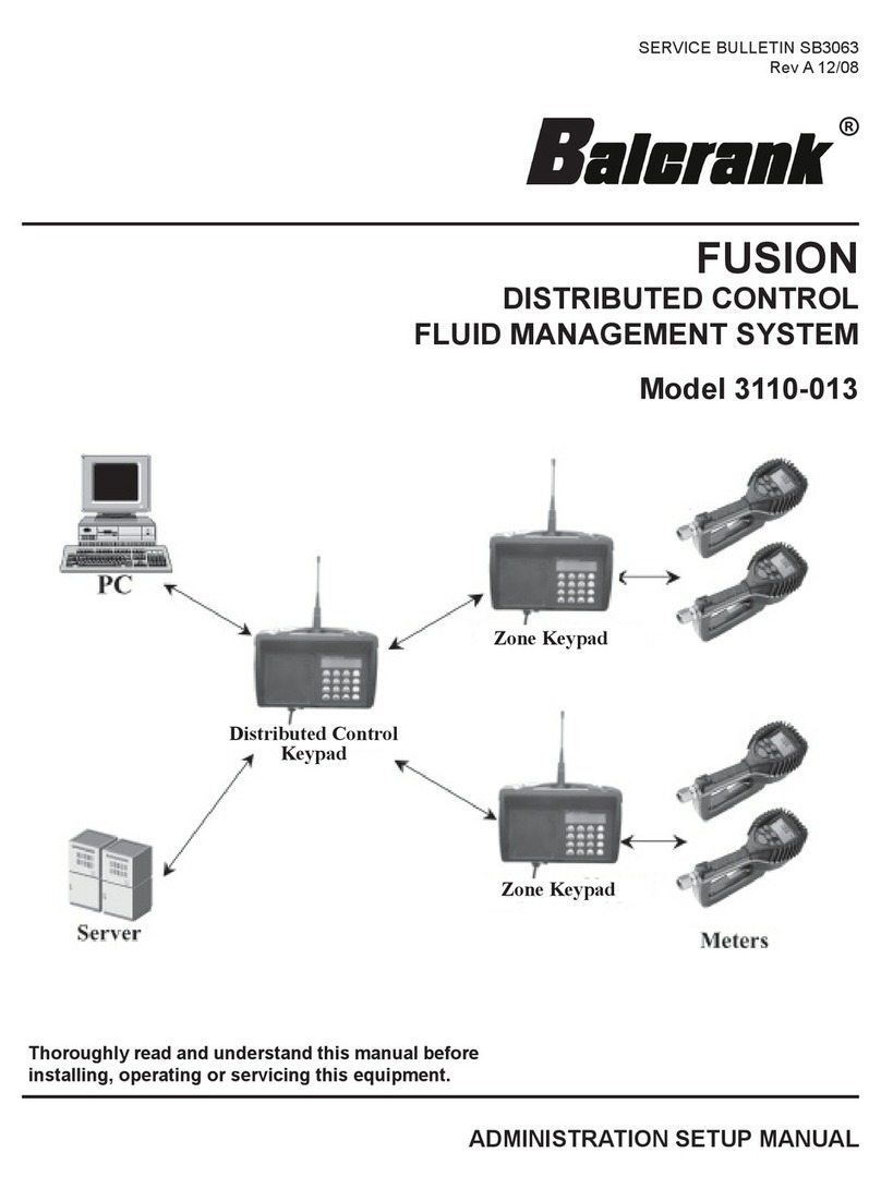
Balcrank Spectrum 100 3110-006P Instruction Manual

Page 1
Service Bulletin SB 3028
Rev H 5/12
Spectrum 100TM V2.6 Electronic Fluid Inventory System
Model 3110-006P .............Queuing ConsoleTM
Model 3120-030................. Smart ControllerTM
Model 3120-031...........................Ready Light
Model 3120-032..............Fluid Solenoid Valve
Model 3120-033................. Air Solenoid Valve
Model 3120-036.......................Power Adapter
Operation, Installation, Maintenance and Repair Guide
Thoroughly read and understand this manual before
installing, operating or servicing described equipment.
®

Page 2
Safety: General Notes, Warnings, and Precautions
Thoroughly read and understand this manual before
installing, operating or servicing described equip-
ment. DANGER: Not for use with fluids that
have a flash point below 100 Deg F (38
Deg C, examples: gasoline, alcohol).
Sparking could result in an explosion
which could result in death.
!
WARNING
Turn offpowerattheQueuingConsoleTM
at the end of each workday to eliminate
thehazard ofoilspillsduringunattended
periods.
!
WARNING
Fluid emitted under high pressure from
leaks and/or ruptured components can
penetratetheskin and causeextremely
seriousbodily injury. If anyfluid appears
to penetrate the skin, apply emergency
medical care at once. Do not treat the
penetration as a simple cut. Tell your
physician exactly what type of fluid was
injected into your skin.
!
WARNING
!
Because The SpectrumTM System
controls pressurized oil delivery, the
following safety precautions should be
observed:
1)Check equipmentregularlyandrepair
orreplaceworn and damaged parts.Be
sure fluid connections are tight before
operating this equipment.
2) Adhere to limits of intended use as
describedon page4. Readall limitations
which apply to fluid types, facility limits
and installation configuration.
3) Relieve pressures built up in the
system before any service or repair is
begun. See pressure relief procedure,
this page.
4)Neveralter or modifyanyparts of this
product; doing so may cause damage
and/or personal injury.
CAUTION
Failure to load fluid meter calibration
factor(pulsesper gallon)foreach meter
into SpectrumTM operating software will
result in substantial dispense volume
errors. See pages 37-38.
NOTE
Do not place your hand or fingers over
the dispensing nozzle and/or aim the
nozzleata personat any time.Personal
injury may result.
!
WARNING
Always use the following Pressure
Relief Procedure whenever shutting
off, cleaning, or in any way checking or
servicing pressurized components:
1) Disconnect compressed air line or
turn off power supply at the fluid pump.
2) Point the control handle outlet into
a waste container and open trigger to
relieve pressure.
3) Open any bleed-type supply air
valves and fluid drain valves in the
system.
4) Leave the drain valves open until
you are ready to re-pressurize the
system.
!
WARNING
!
DO NOT TURN OFF CONSOLE IF
JOBS ARE IN QUEUE !
Doingsocanresult in error, “Station not
Available”. Before turning off power to
console, dispense all jobs or delete all
jobsinqueue by using BasicProcedure
BP5: Job Deletion.
If “Station not Avaiable” message
appears, refer to Diagnostic Error Mes-
sage and Code (pg 55); “No Code”
“Station not Available” for recovery
procedures.
CAUTION

Page 3
Table of Contents
Cover ..........................................................1
General Safety Information............................................2
Table of Contents ..........................................................3
Overview ..........................................................4
Purpose of equipment............................................4
Limits of intended use ............................................4
Specifications .......................................................5-7
System Specifications............................................5
Compatible Fluids...................................................5
Component Descriptions.....................................6-7
Configuration Planning..........................................8-11
Planning Worksheet & Instructions .....................8-9
Planning Worksheet: Worked Examples.........10-11
Installation ...................................................12-23
Required tools....................................................12
Installation 41-Step Procedure.....................12-15
Mechanical Detail Illustrations.........................16-17
Pump/meter Installation (fig 20)....................16
Smart ControllerTM Installation (fig 21)..........16
Hose Reel/Ready Light mount (fig 22)..........17
Fluid Valve Installation (fig 23)......................17
Wiring Illustrations...........................................18-23
Complete System (fig 24)..............................18
Console (fig 25).............................................19
Smart ControllerTM (fig 26).............................20
Wire End Detail (fig 27).................................21
Valves and Ready Lights (fig 28,29) .............21
Ground Level Set-up (fig 30).........................22
Impulse Meter (fig 31)...................................23
Basic Operating Procedures (BP).......................24-35
Overview of PIN codes.........................................24
Guide to Basic Procedures...................................25
Special Methods and Suggestions.......................26
BP1: Normal Power Up........................................27
BP2: New Dispense Job......................................28
BP3: Job Status Review ......................................29
BP4: Queue Jumping...........................................30
BP5: Job Deletion................................................31
BP6: Tank Refilling...............................................32
BP7: Inventory Status..........................................33
BP8: Dispense Log..............................................34
BP9: PIN entry/revision........................................35
Special Console Procedures (SP).......................36-46
SP1: Console Initialization ...................................36
SP2: Fluid Identification ..................................37-38
SP3: SC Identification.....................................39-40
SP4: Comm Port Selection ..................................41
SP5: Set Time/Date..............................................42
SP6: System Configuration [save/read]..............43
SP7: System Log .................................................44
SP8: Test All SC’s ................................................45
SP9: SC Comm Test............................................46
Problem Diagnostics and Correction.................47-56
Guide to Diagnostics .........................................47
Error Diagnosis / Action Tables...................48-56
Repair Procedures (RP).......................................57-65
RP1: Replacing Console......................................57
RP2: Replacing Impulse Meter ............................57
RP3: Replacing Air or Fluid Valve........................58
RP4: Replace Ready Light...................................58
RP5: Replace Smart Controller............................59
RP6: Replace Ticket Printer.................................59
RP7: Add One or More Stations...........................59
RP8: Add Another Fluid to System.......................60
RP9: Verification of Comm/Power Wiring.............61
RP10: Verification of Valve Port Wiring................61
RP11: Verification of Inactive Port Setup .............62
RP12: Troubleshooting SC Problems ..................62
RP13: Ground Level SC Identification .................63
RP14: Setting up for Future Expansion................63
RP15: System Restore from Error .......................64
RP16: Troubleshooting SC Magnetic Polling.......64
RP17: Troubleshooting Oil Quantity Errors..........65
RP18: Assuring a Suitable Power Supply............65
Cable Substitutions......................................................66
PIN Code Record Form...............................................67
Warranty ........................................................68

Page 4
and trouble diagnostics are built-in, to speed
analysisand repairif something iswrong. Electronics
components are robust and resistant to the effects
of shop electrical noise, temperature and humidity
variation, oil and dust.
Effective Information Handling...
TheSpectrumTM systemfeatures an optional jobticket
printer which records dispense data as each job is
completed.Alternately, the system may be used with
an optional computer interface to off-load data to a
host PC, for analysis in an AccessTM database
Intended use...
For successful installation and operation of Spec-
trumTM systems, observe the following limits of
intended use:
System installation distance limits: 1100 ft. from
console to most distant solenoid valve.
Dispense from centralized fluid reservoirs to a
network of dispense points, rather than having one
reservoir and pump for each dispense location.
Use SpectrumTM air solenoid valves to operate the
air supply to each pump. The system is not designed
to operate without these valves.
Do not substitute valves, cable or other devices in
place of SpectrumTM components. Substitution may
cause malfunction, or loss of eligibility for Balcrank’s
warranty.
This equipment is designed for indoor use only.
SpectrumTM systems are for use with specified
automotive service fluids only.
Do not attempt to exceed dispense point or station
capacity limits using unusual wiring schemes.
Be sure to provide electric power from sources
with surge protection and ground fault interrupt
protection.
To secure fluid inventory against theft or misuse,
use the PIN code protection system provided in
SpectrumTM software.
Specifications: Overview
The SpectrumTM System...
Is a fluid inventory control system designed to
operate, measure and control fluid distribution
from centralized reservoirs to multiple dispense
points.
True Control of Fluid Inventory...
The system features precise measurement of
dispensed fluids in convenient units of measure.
It provides comprehensive security to prevent oil
theft, tailored through software options to provide
levels of control and operator records to match
the level of detail desired by the user. Records
of each dispense job are created and stored in
console memory.
Dispensing Ease...
SpectrumTM allows simultaneous dispensing of
unlikeproducts. It alsofeatures a uniqueautomated
job control system which allows the user to set up
dispense jobs in an authorization queue. Console
operating process steps are easily edited and
verified. Units of measure are programmable.
Made for Performance-Oriented Facilities...
Spectrum 100TM has control capacity for moderate-
sizefacilities:upto 16-station controlfor3or4 fluids,
32 station control for 2 fluids or 64 station control
for a single fluid. Components are compatible with
automotive service fluids: petroleum and synthetic
motor oils, gear oils, ATF, anti-freeze mixes (not
windshield washer fluid). The wiring and control
architecture is built around a simple power and
communications network, with Smart ControllerTM
nodes near the dispense stations. Self test routines

Page 5
System Capacity:
The Spectrum 100TM system has a control capacity
for dispensing 4 fluids at 1-16 stations or 3 fluid at
1-16 stations, or 2 fluids at 1-32 stations, or 1 fluid
at 1-64 stations.
Metering Method and Accuracy:
The SpectrumTM system is equipped with electronic
digital impulse meters which provide flow measure-
ment of each dispensed fluid, with +/- 0.5 percent
maximum measurement error. The system accom-
modates custom calibration of each meter for high
accuracy, including in-place field calibration.
Job Queue and Concurrent Dispensing:
The SpectrumTM system is capable of simultaneous
dispensing of unlike fluids.
The SpectrumTM system provides microprocessor-
programmed automated sequential dispensing from
a pre-authorized job queue, with provision for 4 jobs
in queue per fluid, in addition to the active job.
TheSpectrumTM system provides, as acontroloption,
automated priority dispensing to a designated “quick
lube service” bay. Dispense jobs designated to
that station move automatically to first place in the
queue program.
System Power and Control:
The SpectrumTM system operates under digital
microprocessor program control, and uses 24 volt
DC to power components.
All solenoid-operated fluid valves in the system use
24 volt DC power, with a maximum of 5 watts power
consumption per solenoid. Maximum operating
distance is 1100 feet from console to the farthest
operated valve.
Job Record Handling:
The SpectrumTM system is equipped with a com-
munication port and optional support software to
allowdispenserecorddata transfer to ahostPersonal
Computer.
TheSpectrumTM systemisequippedtouseanoptional
ticket printer, which prints on standard adding-
machine paper tape rolls. The printer is capable of
printinga record ofeachdispense job andassociated
data, as well as daily and monthly historic dispense-
log reports.
Specifications: Product Specifications
Dispense Control and Tracking:
The SpectrumTM system control program is protected
from unauthorized dispensing operations. PIN
identification codes are assignable for all operators,
with reserved priority PIN numbers for program
management and equipment set-up functions.
Tank Level Monitoring:
The SpectrumTM system maintains and displays
electronic tank level records, including current tank
level, tank capacity and tank low-alert levels. The
system also displays an alert message whenever
low levels are reached.
Operating Pressure and Flow Ranges:
Fluid solenoid valves used with the SpectrumTM
system are rated for 1500 psi working pressure. Air
solenoid valves used with pumps in the SpectrumTM
system are rated for 200 psi working pressure.
Impulse meters used with the SpectrumTM system
are rated for 1000 psi working pressure. SpectrumTM
system components are compatible with fluid flow
rates of 0-6.0 gallons per minute.
Ready Lights:
Each dispense point is equipped with a signal
light to indicate readiness to dispense. The lights
are actuated and automatically sequenced by the
Spectrum Queuing ConsoleTM.
System Automated Self-test:
The electronic controls in the SpectrumTM system are
equipped to conduct a system self-testing diagnostic
procedure each time the console is powered up.
Compatible Fluids:
SpectrumTM system components are compatible
with automotive service fluids: petroleum and
synthetic motor oils, gear oil, ATF, ethylene glycol
(not windshield washer fluid).
DANGER: Not for use with fluids that
have a flash point below 100 Deg F (38
Deg C, examples: gasoline, alcohol).
Sparking could result in an explosion
which could result in death.
!
WARNING

Page 6
Specifications: System Components
Figure 5
Model 3110-006P
Spectrum 100TM Queuing Console
(Console-only service replacement p/n 831342; see SB3028
for repairs and service parts)
Console dimensions 7” x 5.5” x 1.5”. Includes one Model
3120-036 AC Power Adapter. Features Mini DIN port for acces-
sory printer. Power switch and power-in plug on back side.
Fluid Label set and Smart ControllerTM Decal set are included.
Figure 6
Model 3120-030
Smart ControllerTM
Controller Dimensions 2-5/8” x 2-1/8” x 1-1/8”. Mounted with two
No. 8 screws (included). Includes 8 removable wiring terminal
plugs. Operates on 24 VDC power from the console. Controls air
and fluid solenoid valves, operates ready lights and stores Queu-
ing ConsoleTM system configuration data in backup memory.
Figure 7
Model 3120-032
Fluid Solenoid Valve
Valve Dimensions 1-3/4” x 2” x 4-1/2”. Rated 1500 psi. working
pressure. Compatible with motor oils, ATF, gear oil, anti-freeze
mix to 50-50. 1/2” NPT ports. Solenoid is rated for 24 VDC
service. Order one per dispense point.
Figure 8
Model 3120-033
Air Solenoid Valve
Valve Dimensions 1-3/4” x 2” x 4-1/2”. Rated 200 psi. working
pressure. For on/off control of air-operated pumps. 3/8” NPT
ports. Solenoid is rated for 24 VDC service. Order one per pump.
Figure 9
Model 3120-085 (for Tiger, Panther pumps)
Model 3120-086 (for Panther 5:1 pumps)
Model 3120-023 (for 50 Series Diaphragm pumps)
Model 3120-024 (for 100 Series Diaphragm pumps)
Model 3120-087 (for Lion 10:1 pumps)
Pressure Relief Valves
Protects oil distribution system from possible overpressure
damage due to fluid thermal expansion. Select correct model
from the Balcrank Catalog based on the pump model used. Pres-
sure relief valves must be installed in all SpectrumTM systems to
assure eligibility for product warranty. Order one per pump.
Figure 10
Model 3120-039
Long Distance Printer Cable
250 Ft. length cable connects communications port from Model
3120-026 Ticket Printer to Model 3110-007 Queuing Console,
allowing remote viewing of printer reports. Up to two extensions
may be used in series to provide printer operating distance up
to 500 feet.

Page 7
Specifications: System Components
Figure 11
Model 3120-035
Ticket Printer (Optional)
Dimensions 4.1” x 4.5” x 2”. Impact dot matrix printer, prints
system dispense reports on 24 character line width using 2.25”
cash register paper tape roll. Includes 3 ft. communication cable
and power adapter with 6 ft. cord.
Figure 12
Model 3120-010
In-line Strainer
For use in the fluid line prior to fluid solenoids to assure reliable
valve operation. 3/4” NPT ports. Cleanable filter. Order one per
fluid solenoid valve.
Figure 13
Model 3120-103
Impulse Meter
(see SB3073 for repairs and service parts)
Dimensions 3” x 3 ¼” x 2 ¾”. In-line mounting with 1/2” NPS
ports. Rated 1000 psi. maximum working pressure. Oval gear
movement transmits magnetic pulse to detector circuit, which
pulses a nominal 12 volt signal to the Spectrum Queuing Conso-
leTM. Order one per pump.
Figure 14
Model 3120-031
Ready Light
Mounts directly in .500” diameter hole now provided on all Bal-
crank hose reels. Bright green LED lamp. Operates on 24 VDC.
Order one per fluid solenoid valve.
Figure 16
Models 3121-xxx Cable, Communications/Power
3122-xxx Cable, Impulse Meter
3123-xxx Cable, Solenoid
Cables are configured to simplify system installation and provide
reliable operation. Three cable styles are used, available in 100,
150, 200, 250, 500 and 1000 ft. lengths. Refer to layout planning
sheet, SpectrumTM installation instructions and Balcrank price list.
Dash number =cable length in feet.
Partsofthe SpectrumTM product warranty
may be void if the system is not equipped
withproperly selected filter-regulators,fluid
line strainers and pressure relief kits.
NOTE
Figure 15
Model 3120-026
PC Interface Kit (Optional)
(see SB3034 for repairs and service parts)
Includes 8 ft. long interface cable and compact disc with software
to download dispense reports to a host PC. Results are prepared
as standard AccessTM database. PC Interface cannot be used if
Model 3120-035 Ticket Printer is utilized.

Page 8
Configuration Planning Procedure:
Use the following procedure to complete and fill out the
Configuration Planning Worksheet, opposite page:
1Determine the number of system fluids to be
dispensed.
2
If the number of fluids in the system is 3 or 4, or if
you will configure for future expansion, you must use
the standard fluid configuration plan. Up to 16 stations
are permitted.
3
If the number of fluids in the system is 2 and you
are not configuring for future expansion, you must
use the dual fluid configuration plan. Up to 32 stations
are permitted.
4
If the number of fluids in the system is 1 and you are
not configuring for future expansion, you must use
the single fluid configuration plan. Up to 64 stations
are permitted.
5
Above the station blocks for the service area, write in
the fluid types for each of the fluids to be dispensed,
working left to right. Fill in both LH and RH fluid type
blocks. Also enter fluid types in the designated row of
the air station block.
6
In the first service area station block (next to SC01),
fill in the station row: use 1,1,1,1 for standard plan,
1,1,2,2 for dual fluid plan, 1,2,3,4 for single fluid plan.
7
Inthesecond service areastationblock (next toSC02),
fill in the station row: use 2,2,2,2 for standard plan,
3,3,4,4 for dual fluid plan, 5,6,7,8 for single fluid plan.
8
Continue filling in additional station rows, using
sequential numbering in a similar manner, until the last
entered number is equal to the total number of stations
in your system.
9
Now enter check marks in all of the numbered station
blocks, but only beneath port positions which will
be used.
10
Now compile an equipment requirements list,
next column, using the information on the Planning
Worksheet.
11 During worksheet preparation, for each fluid, enter
tank size, alarm level amount, fluid type and
estimated current tank level (all in gallon units). At
factory set-up time, Balcrank will add meter PPG factors.
At field installation time, adjust exact tank current-level
amounts.
12 Record the user name and location, distributor
name and distributor PO number.
13 Indicate by checked box whether the system will
include a ticket printer. If a quick lube bay is to be
used, identify the designated quick lube bay.
14 All systems are factory pre-programmed and will
be shipped with a copy of your completed planning
sheet, with final information added.
Save this information as a record of configuration for
future use in equipment expansion or repair.
Planning: Configuration Planning Procedure
Equipment list:
3120-030 Smart ControllerTM.Order one per checked
station block, including the air block.
3120-031 Ready Light. Order one per check mark in the
combined service area station blocks.
3120-032 Fluid Solenoid Valve. Order one per check
mark in the combined service area station blocks.
3120-033 Air Solenoid Valve. Order one per fluid used
in the air station block.
3110-006P Spectrum 100 Console. Order one per
system.
3120-039 Extension Cable for Printer. (optional) Allows
printer to be up to 250 ft from console. Use two to go
500 ft. max.
3120-035 Ticket Printer. (optional). Order one per
system.
3120-026 Host PC Interface. (optional). Order one per
system. Do not combine printer with PC interface.
3120-103 Impulse Meter. Order one per check mark in
the air station block.
3123-xxx Solenoid Cable, 3121-xxx Comm/Power
Cable, 3122-xxx Impulse Meter Cable. Use the system
wiring diagram to assist in identifying where each cable
type is used. Actual facility dimensions will determine best
order lengths. Select cable spools lengths from a range of
model choices, shown in the Balcrank price list.
Definitions:
SC: SmartController,an electronic control card whichmanages operation
of fluid solenoid valves in the service bay areas and air solenoid valves
in the pump room.
Port: A solenoid actuator location on the electronic Smart Controller.
A port equates to a single fluid dispense point, or to a single on/off
valve for an air pump.
Station: an individual dispensing location, with 1 to 4 dispense points,
in the service area. Note that a station may serve more than one bay
whenever dispensing handles are shared by operators.
Model Description Quantity
3120-030 Smart Controller
3120-031 Ready Light
3120-032 Fluid Solenoid Valve
3120-033 Air Solenoid Valve
3110-006P Queuing Console
3120-039 Printer Extension Cable
3120-035 Ticket Printer
3120-103 Impulse Meter
3123-xxx Solenoid Cable
3121-xxx Comm/Power Cable
3122-xxx Impulse Meter Cable
3120-026 Host PC Interface

Page 9
SC 01
SC 02
SC 03
SC 04
SC 12
SC 11
SC 16
SC 15
SC 14
SC 13
Service Area
Service Area
Station:
Ports:
Station:
Ports:
Station:
Ports:
Station:
Ports:
1 2 3 4
1 2 3 4
1 2 3 4
1 2 3 4
Station:
Ports:
Station:
Ports:
Station:
Ports:
Station:
Ports:
Station:
Ports:
Station:
Ports:
1 2 3 4
1 2 3 4
1 2 3 4
1 2 3 4
1 2 3 4
1 2 3 4
SC00 Air Station Block
Station:
Ports:
Fluid Type:
Meter PPG
Tank Size
Alarm Amt
Current Amt
1 2
SC00 Air
Service Area Blocks
Fluid Type
Fluid Type
Balcrank Spectrum 100
TM
Configuration Planning Sheet
User:
User City, State:
Balcrank Distributor:
Distributor PO No.:
F5192 Rev A 7/04
for factory entry only:
3 4
Pump Room
Parts
Counter
SC 00
Air
Balcrank Sales Order No.:
Pre-programming Date:
Console Serial No.:
Programmed By:
SC 05
SC 06
Station:
Ports:
Station:
Ports:
1 2 3 4
1 2 3 4
SC 07
SC 08
Station:
Ports:
Station:
Ports:
1 2 3 4
1 2 3 4
SC 10
SC 09
Station:
Ports:
Station:
Ports:
1 2 3 4
1 2 3 4
Service Area Blocks
Console
(or) Printer:
Quick Lube Bay:
Bay Number:
PC:
Configure for future expansion:
6
8
7
5
5
12
9
9
9
9
Figure 17
Planning Worksheet for
Spectrum 100TM System Installation
Avaliable as Form F5192
13
Planning: Configuration Planning Worksheet
11

Page 10
Planning: Configuration Worksheet Example
Figure 18
Planning Worksheet: Worked Example
Spectrum 100TM System Installation
4 Stations, 2 Fluids per station, configured for expansion
SC 01
SC 02
SC 03
SC 04
SC 12
SC 11
SC 16
SC 15
SC 14
SC 13
Service Area
Service Area
Station:
Ports:
Station:
Ports:
Station:
Ports:
Station:
Ports:
1 2 3 4
1 2 3 4
1 2 3 4
1 2 3 4
Station:
Ports:
Station:
Ports:
Station:
Ports:
Station:
Ports:
Station:
Ports:
Station:
Ports:
1 2 3 4
1 2 3 4
1 2 3 4
1 2 3 4
1 2 3 4
1 2 3 4
SC00 Air Station Block
Station:
Ports:
Fluid Type:
Meter PPG
Tank Size
Alarm Amt
Current Amt
1 2
SC00 Air
Service Area Blocks
Fluid Type
Fluid Type
Balcrank Spectrum 100
TM
Configuration Planning Sheet
User:
User City, State:
Balcrank Distributor:
Distributor PO No.:
for factory entry only:
3 4
Pump Room
Parts
Counter
SC 00
Air
City Oil Company
Los Angeles, CA
Jerry's Auto Mart
81339
03
FUTURE
10 W 30
522
500
100
417
ATF
518
275
80
210
FUTURE
522
500
100
417
Balcrank Sales Order No.:
Pre-programming Date:
Console Serial No.:
Programmed By:
10037 V3.2
7/21/04
242355
Larry Smith
1 1
2 2
3 3
4 4
1
10 W 30
ATF
2
3
4
SC 05
SC 06
Station:
Ports:
Station:
Ports:
1 2 3 4
1 2 3 4
SC 07
SC 08
Station:
Ports:
Station:
Ports:
1 2 3 4
1 2 3 4
SC 10
SC 09
Station:
Ports:
Station:
Ports:
1 2 3 4
1 2 3 4
Service Area Blocks
Console
(or) Printer:
Quick Lube Bay:
Bay Number:
PC:
Configure for future expansion:

Page 11
Planning: Configuration Worksheet Example
SC 01
SC 02
SC 03
SC 04
SC 12
SC 11
SC 16
SC 15
SC 14
SC 13
Service Area
Service Area
Station:
Ports:
Station:
Ports:
Station:
Ports:
Station:
Ports:
1 2 3 4
1 2 3 4
1 2 3 4
1 2 3 4
Station:
Ports:
Station:
Ports:
Station:
Ports:
Station:
Ports:
Station:
Ports:
Station:
Ports:
1 2 3 4
1 2 3 4
1 2 3 4
1 2 3 4
1 2 3 4
1 2 3 4
SC00 Air Station Block
Station:
Ports:
Fluid Type:
Meter PPG
Tank Size
Alarm Amt
Current Amt
1 2
SC00 Air
Service Area Blocks
Fluid Type
Fluid Type
Balcrank Spectrum 100
TM
Configuration Planning Sheet
User:
User City, State:
Balcrank Distributor:
Distributor PO No.:
F5192 Rev A 7/04
for factory entry only:
3 4
Pump Room
Parts
Counter
SC 00
Air
Texas Pump Service
Austin, TX
Car City
81339
10 W 30
522
500
100
417
ATF
518
275
80
210
Balcrank Sales Order No.:
Pre-programming Date:
Console Serial No.:
Programmed By:
10037 V3.2
7/21/04
242355
Larry Smith
1 1
3 3
5 5
7 7
10 W 30
ATF
10 W 30
ATF
10 W 30
ATF
10 W 30
ATF
2 2
4 4
6 6
8 8
9 9 10 10
11 11 12 12
13 13 14 14
15 15 16 16 17 17 18 18
19 19 20 20
SC 05
SC 06
Station:
Ports:
Station:
Ports:
1 2 3 4
1 2 3 4
SC 07
SC 08
Station:
Ports:
Station:
Ports:
1 2 3 4
1 2 3 4
SC 10
SC 09
Station:
Ports:
Station:
Ports:
1 2 3 4
1 2 3 4
Service Area Blocks
Console
(or) Printer:
Quick Lube Bay:
Bay Number:
PC:
Configure for future expansion:
Figure 18
Planning Worksheet: Worked Example
Spectrum 100TM System Installation
20 Stations, 2 Fluids per station, some of the ports not used

Page 12
Installation: Step-by Step Procedure
Required Tools & Materials:
Jeweler’s screwdriver, flat 2 mm blade
Permanent magnet, small
Portable power drill
1.50” dia. drill bit or hole saw (if needed, step 10)
.500” dia. drill bit (if needed, step 14)
No. 29 (.136” dia.) drill bit
Wire cutting and stripping tool
11/32” open-end wrench
Small Phillips screwdriver
Pliers for wire crimping
2 pipe wrenches for 1/2” to 1” NPT range
1-gallon certified fluid measuring container, with
1-cubic-inch calibration scale
Cable ties
Wire connectors, screw cap or crimp-lug type
Procedure:
Installation Planning:
1A “SYSTEM PLANNING WORKSHEET” [Figure
17, page 9] was created to accompany your
Spectrum purchase order at Balcrank. Locate your
copy of the worksheet, which was shipped with the
equipment order.
2
Check for completeness of on-hand parts &
components. Match component quantities to the
results of the “SYSTEM PLANNING WORKSHEET”
analysis (see page 8).
!
Useonly specifiedBalcrank SpectrumTM
system components. Substitutions
may cause reduced product perfor-
mance levels, signal and information
errors or electrical hazard. Additionally,
SpectrumTM warranty will be void if
substitute components are installed in
the system.
CAUTION
Installing Pump Room Components:
3Be sure pumps are equipped with air filter-
regulators, air shutoff valves, pressure relief
kits, pump outlet shutoff valves and suction air
eliminators.See “PUMPINSTALLATION DIAGRAM”,
[Figure 20, page 16].
4Install in-line Impulse Meters (model 3120-103)
at each pump, as factory-marked for Fluid 1,
Fluid 2, etc.
5
InstallAir Valves (model 3120-033) at each pump;
locatevalvesbetween the pumpsandtheirrespec-
tive filter-regulators. See “PUMP INSTALLATION
DIAGRAM”, [Figure 20, page 16].
6
Install the Smart ControllerTM marked “SC00, air”
(model 3120-030) approx. 8 ft. high on the wall,
adjacenttothe pumps, using No.8fastenerssupplied,
power drill, No.29 drill bit, Phillips screwdriver and
11/32”wrench.See“INSTALLATION DETAIL,SMART
CONTROLLER”, [Figure 21, page 16].
7Run local wiring from the Air Smart ControllerTM
to each Air Solenoid Valve. Use lengths of Sole-
noid Cable (model 3123-xxx). Strip ends per “WIRE
END DETAIL”, [Figure 27, page 21]. Attach wire at Air
Solenoid Valves using crimp connectors or screw
caps. Attach wires at the Smart ControllerTM using
the jeweler’s screwdriver to secure wires to port con-
nectors. Fluid 1 to port 1, fluid 2 to port 2, etc. Refer
to “WIRING DETAIL, AIR VALVES”, [Figure 28, page
21]and“WIRINGDETAIL, SMARTCONTROLLERS”,
[Figure 26, page 20].
!
Be sure air regulators for pumps are
set below 150 psi prior to applying air
pressure. Excessive pressure might
damage pumps.
CAUTION
Parts of the SpectrumTM product warranty
may be void if the system is not equipped
withproperlyselected filter-regulators, fluid
line y-strainers and pressure relief kits.
NOTE

Page 13
Installation: Step-by Step Procedure
Initial Cable Runs & Console Placement:
8Pull one Impulse Meter Cable (model 3122-xxx)
and one Comm/Power Cable (model 3121-xxx)
fromthe pump roomto the partscounter.Allow plenty
of extra cable length to provide for final wiring at each
end location. Secure the cable along this path (onto
convenient existing piping, if available) with cable
ties.
9In the pump room, connect the terminations of
the Impulse Meter Cable (model 3122-xxx) to
the Impulse Meters (model 3120-103) per “WIRING
DETAIL, IMPULSE METERS”, [Figure 31, page 23].
Be sure to use the correct black wire associated with
each colored wire, just as they are spiral-wrapped on
the cable. Terminate with crimp connectors or screw
caps.If less than4Impulse Meters areused,cut back
unused wires on the impulse meter cable.
10 Select a suitable location at the parts counter
for the Spectrum Queuing ConsoleTM (model
3110-006P). Provide a 1.50” dia hole in the counter-
top, just behind the planned console location. Place
the Spectrum Queuing ConsoleTM in position. Attach
the connector of the included 6 ft. extension cable to
the back of the console. Mount the cable through the
holeand beneaththe counter (extensioncable disas-
sembly/re-assemblymay be requiredtopass through
thehole). Secure theterminalstripto a below-counter
shelforsidewall,beingsurethatterminal wiring points
are all accessible.
11 AttheQueuing Console extension terminalstrip,
connect wires from the Impulse Meter Cable
(model 3122-xxx) to their assigned empty locations
(outgoing side of terminal strip) using a flat screw-
driver blade to push the terminal opening buttons. Be
sure to match meter fluid-number color codes to the
wiring in the pump room. Refer to “WIRING DETAIL,
CONSOLE”, [Figure 25, page 19].
12 In the pump room, connect the terminations of
theComm/PowerCable (model 3121-xxx) wires
to the input side of the Air Smart ControllerTM (model
3120-030). Secure wires to the terminal plugs using
the jeweler’s screwdriver. Refer to “WIRING DETAIL,
SMART CONTROLLERS”, [Figure 26, page 20].
13 At the parts counter, strip ends of the Comm/
Power Cable (model 3121-xxx) from the pump
room. Connect wires from the pump room Comm/
Power Cable (model 3121-xxx) to their assigned
locations on the extension terminal strip of the Spec-
trum Queuing ConsoleTM. Refer to “WIRING DETAIL,
CONSOLE”, [Figure 25, page 19].
Service Bay Parts & Their Cable Runs:
14 At each dispense point, use the provided .500”
diameterhole in thehose reel orreel enclosure,
as illustrated, “HOSE REEL HOLE LOCATIONS”,
[Figure 22, page 17]. Press one Ready Light (model
3120-031) into the .500” dia. mounting hole on each
of these hose reels.
15 At each dispense point, install a Y-Strainer
(model 3120-010) and a Fluid Solenoid Valve
(model3120-032) intothe supplypiping at eachhose
reel, using the pipe wrenches. Also be sure that fluid
lineshutoffvalvesareinstalled at each dispensepoint
(these are not provided with the SpectrumTM equip-
ment set). Refer to “INSTALLATION DETAIL, FLUID
SOLENOID VALVES”, [Figure 29, page 21].
16 Adjacent to each dispensing station, locate
convenient mounting points for the Smart Con-
trollersTM (model 3120-030), on the facility walls (8
ft. height from floor is recommended), or on support
beams. Select locations which have proximity to the
dispense stations which the Smart ControllersTM are
to control.
17 Mount all of the Smart ControllersTM (model
3120-030) in the exact planning sheet loca-
tions designated by their labels (SC01, SC02, etc)
using the No.8 fasteners packaged with the control-
lers. Match drill .136” diameter holes into the beams
or other convenient structural locations. Tighten
fasteners using the Phillips screwdriver and 11/32”
wrench. Refer to “INSTALLATION DETAIL, SMART
CONTROLLER”, [Figure 21, page 16].
Use care when wiring components.
Prepare wire ends per WIRE END
DETAIL recommendations. Be careful
to match wire color codes to the wiring
diagram specifications.
NOTE
!
Be sure to wire impulse meters cor-
rectly. Reverse wiring or attachment
to wrong terminal points could cause
immediate damage to the circuit board
in the impulse meters.
CAUTION

Page 14
Installation: Step-by Step Procedure
24Placethe console PowerAdapter (model 3120-
036) beneath the counter and plug into the con-
sole. Console power switch should be “OFF”. Leave
the multipin connector detached from the console.
25Plug the console PowerAdapter (model 3120-
036) into an un-interruptable power supply
(UPS) with an 80 watt, 110 VAC rating. Plug the UPS
into a 110 VAC wall receptacle.
26
If the optional Ticket Printer (model 3120-035)
has been purchased, connect the printer power
cordto the same UPSelectricpower source. Connect
the communication cable of the printer to the “PTR”
port on the back side of the console. Load the printer
paper spool, per instructions in the printer box. Then
turn “OFF” printer power switch.
27
If the Host PC Interface (model 3120-035) has
beenpurchased,connect the PC cablebetween
the console and the serial port on the PC, per the
instruction in the Interface Kit.
28
Inthe pump room, determinetheamount of fluid
in each tank. Record tank fluid quantities on the
“SYSTEM PLANNING WORKSHEET”, [Figure 17,
page 9]. Other parts of the worksheet should already
be completed by the factory to accompany your
Spectrum shipment.
18For each dispense point, run one length of
SolenoidCable (model 3123-xxx)from the Fluid
Solenoid Valve to its associated Smart Controller.
Refer to the “SYSTEM PLANNING WORKSHEET”
to assure correct cable run placement. Secure the
cable at suitable locations with cable ties. Refer to
“WIRING DETAIL, FLUID SOLENOID VALVES”,
[Figure 29, page 21].
19
On each Solenoid Valve Cable, strip and mount
the Smart ControllerTM wire ends to the desig-
nated Smart ControllerTM ports using the jeweler’s
screwdriver. Strip the wire ends per “WIRE END
DETAIL”, [Figure 27, page 21]. Refer also to “WIRING
DETAIL, SMART CONTROLLERS”, [Figure 26,
page 20]. Attach wires at the valve end using crimp
connectors or screw caps. Be sure to include Ready
Lightwires inthe valve-endconnections, as shown in
the “WIRING DETAIL, FLUID SOLENOID VALVES”,
[Figure 29, page 21].
20Runone Comm/Power Cable(model 3121-xxx)
betweeneachof the SmartControllersTM,begin-
ning with the controller nearest the parts counter and
ending with the controller most distant from the parts
counter. Run cables in a single chain (no branch-
ing).Strip per “WIRE END DETAIL”, [Figure 27, page
21] and attach wire ends to the designated terminal
plugs on the Smart ControllersTM using the jeweler’s
screwdriver. Refer to “WIRING DETAIL, SMART
CONTROLLER”, [Figure 26, page 20]. Secure cables
using wire ties.
21
Run one Comm/Power Cable
(model 3121-xxx)
from the Smart ControllerTM nearest the parts
counter to the Spectrum Queuing ConsoleTM. Secure
cable using wire ties.
22
Install a tail-end resistor (one is furnished with
each Smart Controller) across the OUT (+) and
OUT (-) terminals on the Air Smart Controller in the
pump room and on the farthest Fluid Smart Control-
ler in the service bays
. Refer to “Wiring Detail, Smart
Controller”, [Figure 26, page 20].
Queuing Console Installation
23Atthepartscounter, terminatetheconsoleendof
the Comm/Power Cable (model 3121-xxx) from
the service bays. Attach wire ends at the designated
terminal points on the extension cable terminal strip.
Useaflatscrewdriverbladetopushtheterminalopen-
ing buttons. Refer to “WIRING DETAIL, CONSOLE”,
[Figure 25, page 19].
!
Use gentle movement to remove or
install the multipin connector in the
console.Heavyforce could damagethe
connector or its mating part.
CAUTION
For improved operating reliability,
it is highly recommended that the
consolepower adapterandticket printer
power plug be installed through an un-
interruptable power supply (UPS) with
an 80 watt rating.
NOTE

Page 15
Queuing Console Program Setup
29
With console power “OFF”, install the multipin
connector plug into the slot in the back face of
the console. Turn the console power “ON”. Also turn
“ON” the ticket printer, if used. Allow the console to
completeaself-testcycle,whichshouldendat“SPEC-
TRUM 100 / IDLE”. If you observe an error message
at power-up, use the “ERROR DIAGNOSIS GUIDE”,
[pages 47-56],beforeproceedingfurther.CallBalcrank
for factory assistance if required.
30
Edit some of the set-up fluid parameters by
following the procedure “FLUID IDENTIFICA-
TION“, [Procedure SP2, page 37-38]. Step through
the procedure without changing existing entries
except current tank amount. Edit current tank
amount for each fluid to show correct quanties now
in the tanks.
31
Leaveconsolepower“ON”.Completeprocedure
“PINENTRY/REVISION”, [Procedure BP9, page
35].AssistthecustomerinsettinguppersonalI.D.PIN
codesforservicetechniciansandmanagers.Havethe
customer record and store PIN code information in a
secure place. A convenient record form is available
on page 67.
32
Cycle console power. If time and date are incor-
rectatconsole start-up, completetheprocedure
“SET TIME/DATE”, [Procedure SP5, page 42].
Purging Air and System Check Out
33Check in the pump room to be sure that all air
supply valves to the pumps are open; for best
operation, set air regulators to 70-100 psi. Open all
fluid shutoff valves in the system.
34
Have an attendant stand ready at station 1
with a 1-gallon calibrated measure container.
Authorizeanddispense 1.0 gallonsoffluid1using the
procedure “NEW DISPENSE JOB”, [Procedure BP2,
page 28]. Observe for correct operation of the Ready
Light. Check to be sure the correct fluid is dispensed
to station 1. If air is present in the fluid piping, less
than 1.0 gallons will be dispensed. Therefore, repeat
this procedure until the dispensed quantity reaches
1.0 gallon and becomes consistent. Then dispose or
return the test fluid.
35
Repeat procedure step 34 for each of the addi-
tional fluids at station 1.
36
Repeat the procedure steps 34-35 at all other
dispensing stations.
37
Again, turn Power “OFF” and then “ON” at the
console. Allow the console to complete a self-
test cycle, which should end at “SPECTRUM 100 /
IDLE”. If you observe an error message at power-up,
use the troubleshooting guide, pages 47-56, before
proceeding further. Call Balcrank for factory assis-
tance if required.
38
Re-save all system set-up parameters by fol-
lowing the procedure “SYSTEM CONFIGURA-
TION“, [Procedure SP6, page 43].
39
If the optional Host PC Interface (model 3120-
035)hasbeen purchased, complete allsoftware
installation per instructions supplied in the option
package, including test dispenses.
User Training and PIN Records
40Review all console basic procedures with all
authorized customer users. Review manage-
ment procedures with the designated SpectrumTM
user equipment manager.
41
Installation is now complete and ready for dis-
pensing service.
Installation: Step-by Step Procedure
It is strongly recommended that PIN
codeidentificationbe setupand utilized
in all SpectrumTM installations. This
assures the full protection against
fluid theft or mis-use which has been
provided in the product design.
NOTE

Page 16
Figure 20
Pump Installation Diagram
Figure 21
Installation Detail, Smart Controller
Illustrations: Pump & Smart Controller
Typical Air Operated Pump
(Panther 300 with bung
adapter shown)
Model 3120-033
Air Solenoid Valve
Model 3260-048 Lubricator
Air Line Filter and Pressure
Regulator
Model 3120-103
Electronic Impulse
Meter
Pressure Relief Kit
See page 6 for selection
1/2” NPS fluid line and fittings
Model 3120-003
Air Line
Hand Shutoff Valve
FluidLineHandShut-
off Valve and outlet
check valve
For mounting, match drill 2 holes in
the mounting structure, 0.136 dia
x 1.50” centers. Install with No. 8
Screws, nuts and washers ( included
with each smart controller).
Location of the magnetic trigger zone,
adjacent to the center LED lamp. For
location detail, see Figure 26, page 20.
Wire connector plugs

Page 17
Figure 23
Installation Detail, Fluid Solenoid Valve
Illustrations: Fluid Valve & Ready Light
Figure 22
Installation Detail, Hose Reel Hole Locations
Signature Reels:
Ready light presses into
0.500” dia. hole, located as
shown.
Note Ready light and sole-
noid valve wiring, secured to
the reel with cable ties.
Premium Reels:
Ready light presses into
0.500” dia hole, located as
shown.
Note Ready light and
solenoid valve wiring,
secured to the reel with
cable ties.
Premium Reels:
Fluid Solenoid Valve
connectstohose reel
swivelusing 1/2”NPT
close nipple.
Signature Reels:
Fluid Solenoid Valve
connectstohose reel
1/2” NPT port using
a close nipple.
Inlet Hose, hand shutoff
valve, y-strainer
Enclosed Deluxe Reels: Ready
light presses into
0.500” dia. hole on outlet cast-
ing, located as shown. Secure
cable with ties internally.
Inlet Hose, hand shutoff
valve, y-strainer

Page 18
3120-033
Air Solenoid
Valve
3 Req'd
3120-031
Ready Light
9 Req'd
3120-032
Fluid Solenoid
Valve
9 Req'd
3122-xxx
Impulse Meter
Cable
1 Section
3123-xxx
Solenoid
Cable
12 Sections
3120-034
Digital Impulse
Meter
3 Req'd
3110-006
Queuing Console
1 Req'd
3121-xxx
Power/Signal
Cable
4 Sections
3120-030
Smart
Controller
4 Req'd
Illustrations: System Wiring Example
Figure 24:
Wiring Diagram
Spectrum 100 Fluid Inventory Control System
3 Fluid x 3 Station Configuration Shown
3120-103
Impulse

Page 19
Illustrations: Queuing Console Wiring
Figure 25:
Wiring Detail
Spectrum Queuing Console
Impulse Meter Cable
Model 3122-xxx
to Meters
WHITE / BLUE
BLUE / WHITE
BARE WIRE
BLACK
WHITE
WHITE / BLUE
BLUE / WHITE
BARE WIRE
Fluid 1
Fluid 2
Fluid 3
Fluid 4
BLACK
WHITE
BLACK
BLUE
BLACK
GREEN
BLACK
WHITE
BLACK
RED
Power/Signal Cable Model 3121-xxx
to SC 00 Smart Controller, Air
Power/Signal Cable Model 3121-xxx
to SC 01 Smart Controller, Station 1
Impulse Meter Cable Model 3122-xxx
to Impulse Meters
M- M+
M- M+
M- M+
M- M+
C- C+ P- P+
SC- C+ P- P+
S
Power
Power
Signal
Signal
Queuing Console
Model 3110-006P
Multipin Connector Detail
Queuing Console
Model 3110-006P
Power/Signal Cable
Model 3121-xxx
to Smart Controller SC 01
(Service Area) Power/Signal Cable
Model 3121-xxx
to Smart Controller SC 00
Air (Pump Room)
Queuing Console
Model 3110-006P
Enlarged Detail
Top View

Page 20
Illustrations: Smart Controller Wiring
Figure 26:
Wiring Detail
Smart Controller
Enlarged Wiring Detail
Smart Controller
Installed
Smart Controller
With Cables
Attached
Smart Controller,
Showing Use Of
Tail-end Resistors
Solenoid Cables
Model 3123-xxx
to Fluid Solenoid Valves
or Air Solenoid Valves
Power/ Signal Cable
Model 3121-xxx
from Queuing Console or
prior Smart Controller
Smart Controller
Model 3120-030
Power/ Signal Cable
Model 3121-xxx
to next Smart Controller
PORT 1
PORT 2
PORT 3
PORT 4
IN OUT
Smart Controller
Model 3120-030
Power
Power
BLUE / WHITE
WHITE / BLUE
BARE WIRE
WHITE
BLACK
+++
SS
--+--
BLUE / WHITE
WHITE / BLUE
BARE WIRE
WHITE
BLACK
Signal
Signal
IN OUT
-+-+-+-+
BLACK
RED
BLACK
RED
BLACK
RED
BLACK
RED
PORT 1
PORT 2
PORT 3
PORT 4
Detection
Zone
for Magnetic
Initialzing
Smart Controller
Model 3120-030
IN OUT
PORTS 1-4
Tail End Resistor (120 K Ohm)
Supplied with Smart Controller.
Mount on output connector,
"Signal Out +" to "Signal Out -"
Air SC and last Fluid SC Only.
Use Tail End Resistors Temporarily
Only During Selected Set-up Tests
In Place of an Attached Valve.
Center LED
Output Port
LED's (4)
This manual suits for next models
5
Table of contents
Other Balcrank Control System manuals
Popular Control System manuals by other brands

ProFire
ProFire PF3100 FARC user guide

Rehau
Rehau NEA SMART 2.0 Service manual

CNC Router Parts
CNC Router Parts CRP600 Benchtop PRO Assembly instructions

Siemens
Siemens SIMATIC PCS 7 System manual

Lincoln Electric
Lincoln Electric Torchmate 4400 user guide

Ascon tecnologic
Ascon tecnologic AC3nP installation manual

IntelligentAg
IntelligentAg Engage Zone Control Information Notice

LINK ELECTRIC & SAFETY CONTROL COMPANY
LINK ELECTRIC & SAFETY CONTROL COMPANY OmniLink II operating manual

THERMEx
THERMEx Pro Link I Series instructions

Potter
Potter SignaLink WSS instructions

Plexon
Plexon HELIOS Technical guide

Burkert
Burkert NAMUR 6517 operating instructions