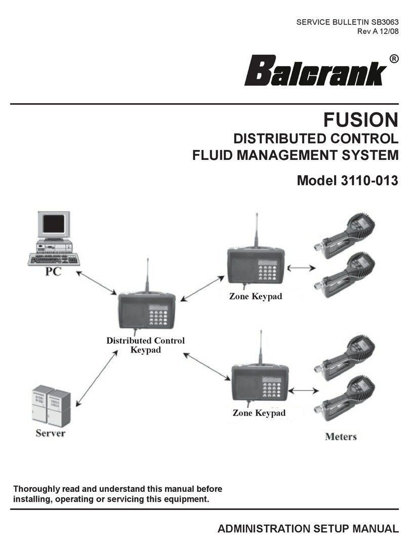
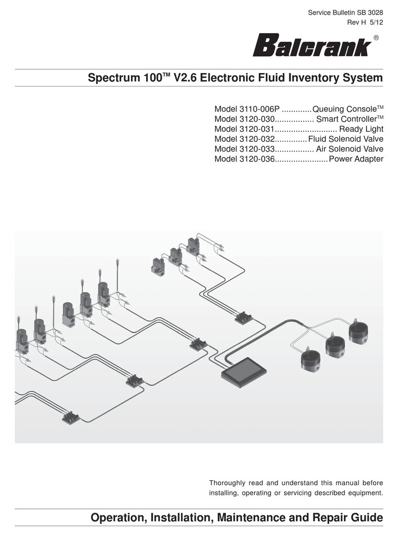
Balcrank Fusion 3110-027 Reference manual

3110-027
3110-029
SERVICE BULLETIN SB3092
Rev C 9/17
Thoroughly read and understand this manual before
installing, operating or servicing this equipment.
INSTALLATION AND CONFIGURATION GUIDE
fusion 2.4 - DCS
®
Model 3110-027������������������������������������������������������������������������������ Master Keypad
Model 3110-028��������������������������������������������������������������������������Dispense Keypad
Model 3110-029��������������������������������������������Dispense Keypad w/internal printer
3110-028
8

CONTENTS
INTRODUCTION � � � � � � � � � � � � � � � � � � � � � � � � � � � � � � � � � � � � � � � � � � � � � � � � � � � � � � � � � 3
System Overview � � � � � � � � � � � � � � � � � � � � � � � � � � � � � � � � � � � � � � � � � � � � � � � � � � � � � � 4
SystemCompositionandDataow..........................................5
Specications........................................................6
Certication . . . . . . . . . . . . . . . . . . . . . . . . . .. . . . . . . . . . . . . . . . . . . . . . . . . . . . . . . 6
Installation/Mounting � � � � � � � � � � � � � � � � � � � � � � � � � � � � � � � � � � � � � � � � � � � � � � � � � � � � � � � � � 7
Keypad Description � � � � � � � � � � � � � � � � � � � � � � � � � � � � � � � � � � � � � � � � � � � � � � � � � � � � 8
Operation Modes � � � � � � � � � � � � � � � � � � � � � � � � � � � � � � � � � � � � � � � � � � � � � � � � � � � � � 9
MASTER KEYPAD � � � � � � � � � � � � � � � � � � � � � � � � � � � � � � � � � � � � � � � � � � � � � � � � � � � � � � � 10
System Version Screen � � � � � � � � � � � � � � � � � � � � � � � � � � � � � � � � � � � � � � � � � � � � � � � � � �10
Settings Overview / Supervisor Menus � � � � � � � � � � � � � � � � � � � � � � � � � � � � � � � � � � � � � � � 10
Initialization (INI) Menu � � � � � � � � � � � � � � � � � � � � � � � � � � � � � � � � � � � � � � � � � � � � � � � � � 10
Conguration(CNF)Menu... . . . ...... . . . ...... . . . . ...... . . . ...... . . . . ...11
Test Communication (DK) Menu � � � � � � � � � � � � � � � � � � � � � � � � � � � � � � � � � � � � � � � � � � � �13
Reports (REP) Menu � � � � � � � � � � � � � � � � � � � � � � � � � � � � � � � � � � � � � � � � � � � � � � � � � � � 13
Radio (RAD) Menu � � � � � � � � � � � � � � � � � � � � � � � � � � � � � � � � � � � � � � � � � � � � � � � � � � � � 14
DISPENSE KEYPAD � � � � � � � � � � � � � � � � � � � � � � � � � � � � � � � � � � � � � � � � � � � � � � � � � � � � � � 17
System Version Screen � � � � � � � � � � � � � � � � � � � � � � � � � � � � � � � � � � � � � � � � � � � � � � � � � �17
Settings Overview / Supervisor Menus � � � � � � � � � � � � � � � � � � � � � � � � � � � � � � � � � � � � � � � 17
Conguration(CNF)Menu. . . . ..... . . ..... . . . ..... . . ...... . . ..... . . ...... 18
Delete Prepared WOs (MET) Menu � � � � � � � � � � � � � � � � � � � � � � � � � � � � � � � � � � � � � � � � � � 21
Reports (REP) Menu � � � � � � � � � � � � � � � � � � � � � � � � � � � � � � � � � � � � � � � � � � � � � � � � � � � 21
190 (Internal Ticket Printer) Menu � � � � � � � � � � � � � � � � � � � � � � � � � � � � � � � � � � � � � � � � � � �22
RFCommunicationTest(LNK)Menu.........................................22
Radio (RAD) Menu � � � � � � � � � � � � � � � � � � � � � � � � � � � � � � � � � � � � � � � � � � � � � � � � � � � � 23
Network Connect (CON) Menu � � � � � � � � � � � � � � � � � � � � � � � � � � � � � � � � � � � � � � � � � � � � 24
SystemOverride (SYS)Menu... ................................. ..... .....25
DispenseKeypadMenuOverview . .... . ..... . .... . .... . ..... . .... . ..... . ...26
DISPENSE PROCESS � � � � � � � � � � � � � � � � � � � � � � � � � � � � � � � � � � � � � � � � � � � � � � � � � � � � � �27
Starting a Work Order � � � � � � � � � � � � � � � � � � � � � � � � � � � � � � � � � � � � � � � � � � � � � � � � � � 27
FUSIONRF METER . . . . .. . . . . . .. . . . . . .. . . . . . .. . . . . . .. . . . . . .. . . . . . .. . . . . . .. .29
Key Description � � � � � � � � � � � � � � � � � � � � � � � � � � � � � � � � � � � � � � � � � � � � � � � � � � � � � � 29
RFMode(StandardPre-SelectionMode)......................................30
Changing the Battery � � � � � � � � � � � � � � � � � � � � � � � � � � � � � � � � � � � � � � � � � � � � � � � � � � 31
Programmingthe FusionRFMeter...... ......... ........... ........... .....31
INSTALLINGANDLAUNCHINGTHE FMS SOFTWARE................ . . . . . . . . . . . . . . . . 32
System Requirements � � � � � � � � � � � � � � � � � � � � � � � � � � � � � � � � � � � � � � � � � � � � � � � � � � 32
FMSSoftwareDescription... . . . . . ........ . . . . . ....... . . . . . ........ . . . . . .32
InstallingtheFMS Server.. .... ... .... ... ....... ... .... ... .... ... .... ... .33
InstallingtheFMS Client .... . .... .... . .... . .... .... . .... . .... ..... .... . ..36
LaunchingtheFMS Software... .... .... .... .... .... .... ... . ... . ... .... ....38
FMSSystemConguration .... . ... . .... .... .... .... .... . ... . .... .... .... .38
USING THE FMS SOFTWARE . . . . . . . . . . . . . . . . . . . . . . . . . . . . . . . . . . . . . . . . . . . . . . . . 39
Setting Up New Users � � � � � � � � � � � � � � � � � � � � � � � � � � � � � � � � � � � � � � � � � � � � � � � � � � 39
SettingUpTanksandFluids. ... .... .... .... ... .... .... .... ... . ... .... .... 40
Setting Up Keypads and Hoses � � � � � � � � � � � � � � � � � � � � � � � � � � � � � � � � � � � � � � � � � � � � 43
System Settings � � � � � � � � � � � � � � � � � � � � � � � � � � � � � � � � � � � � � � � � � � � � � � � � � � � � � � 47
2

INITIALIZE SYSTEM . . . . . . . . . . . . . . . . . . . . . . . . . . . . . . . . . . . . . . . . . . . . . . . . . . . . . . 50
Test CommOption..... . . . . . ........ . . . . . ........ . . . . ........ . . . . . ....50
InitializeAll Option . . . . . ................... . . . . . . . . . . . . . . . . . . . .........51
InitializeChangesOption. . ..... . . .... . . ..... . ..... . . .... . . ..... . ..... . ..51
PARTS DEPARTMENT USER MENU . . . . . . . . . . . . . . . . . . . . . . . . . . . . . . . . . . . . . . . . . . . . 52
CreatingaNewWorkOrder.. .............. ... ... ... ... ... ........... ... ..52
WorkOrder Reports . . ........ . . . . . ....... . . . . . ........ . . . . . ....... . . . . 53
TanksandFluids.. . ..... . . ..... . ..... . ..... . . .... . . ..... . ..... . ..... . .55
TROUBLESHOOTING . . . . . . . . . . . . . . . . . . . . . . . . . . . . . . . . . . . . . . . . . . . . . . . . . . . . . 56
DispenseKeypadErrorMessages...........................................56
MeterErrorCodes . ..... . .... . .... . ..... . .... . ..... . .... . .... . ..... . ...56
WORKSHEETS . . . . . . . . . . . . . . . . . . . . . . . . . . . . . . . . . . . . . . . . . . . . . . . . . . . . . . . . . 57
INTRODUCTION
TheFusion2.4FluidManagementSystemhasbeendesignedtocontrolandmonitortheconsumptionand
inventorybalancesofautomotiveuidproductswithminimalinstallationandprogrammingcosts.
TheDistributedControlSystem(DCS)hardwareconsistsofoneMasterKeypadandatleastoneDispense
Keypadaswellasatleastoneradiofrequency(RF)electronicpresetmeter.TheMasterKeypadmanages
serialcommunicationtothePCandRFcommunicationtotheDispenseKeypadsinthesystem.Thesystem
veriestheoperator’spinnumberandvalidatestheworkordernumber,uidquantitiesandthevalidhose/
meter�
TheMasterKeypadcancommunicatewithupto36DispenseKeypadsthatcanbepositionedtosupportthe
workowofthefacilitythebestway.EachDispenseKeypadcancontrolupto24meters,withamaximumof
250meterspersystem.Thesystemsupportsupto16tanksand16uidsasapartofthesystemcongura-
tion.Thesystemsupports250uniqueoperatorIDsandpinnumbers.
ThesystemusesdirectsequencespreadspectrumRFtechnologytopreventcommunicationproblemswith
otherequipmentinthefacility.TheRFsystemwilllookforaclearchannelfortransmissiontoinsurethatthere
isreliablecommunicationsatalltimes.Communicationdistancesaretypicallyupto300feetwithunob-
structedline-of-sight.Aremoteantennaisavailableforsituationswheremultiplebuildingsareinvolvedinthe
installationorobstructionshinderRFtransmission/reception.
ThePCisusedtocongurethesystem,maintainsystemdataandenterworkorders.Theservicedeskwould
usethePCtoenteraworkorderselectingtheuidandquantityrequired.ThePCcanstackasmanywork
ordersasrequired,limitedonlybythediskstoragespaceofthePC.Thereisnoneedtopredeterminewhere
theworkisgoingtooccur,thisallowstheexibilitytoserviceavehicleatanyopenbayandselectameter
whentheworkisgoingtobeperformed.Whentheworkorderisgoingtobeperformed,theservicepersonnel
simplyenterstheirpinnumber,workorderandhosethatisgoingtobeusedattheDispenseKeypad.Option-
ally,thesystemcanbeconguredtoallowservicepersonneltofreelyenterworkorders,withoutthemrst
beingenteredatthePC.
Thereareanumberofsystemutilizationreportsbyuser,uidtype,tankormetersavailableforthesystem’s
management�
Aunique,patentedfeatureofthesystemisthattheRFmeter’sdispensetriggerislockeduntilanauthoriza-
tionfromthekeypadisreceived.Afterthedispensebatchiscompleted,theusercantopoifmoreuidis
required.Theactualdispensedamountissentbacktothekeypadandthemeterreturnstothelockedstatus.
Additionally,themetercanbeinstalledonportabledollysystemsoeringcontrolandmonitoringofhigh-cost
lubricationproducts.
3

4
System Overview

The main data streams:
1.TheFMSsoftwarestoresthecongurationdatainitsdatabase.
2.ByusingtheInitializeSystemmenuoftheFMSsoftwarethecongurationdatais
senttotheMasterKeypadviatheserialinterfaceandnallyviaradiotoallDispense
Keypads�
3.TheFMSrecordsalldispensesinthedatabase.
5
System Composition and Dataow

6
Certication
•ContainsFCCID:S4GEM35XB
•ContainsIC:8735A-EM35XB
•FCCCERTIFIED,PART15,SUB-PARTC
•CE0681EC-R&TTECertied
ThisdevicecomplieswithPart15oftheFCCRules.Operationissubjecttothefollowing
twoconditions:(1)thisdevicemaynotcauseharmfulinterference,and(2)thisdevicemust
acceptanyinterferencereceived,includinginterferencethatmaycauseundesiredopera-
tion�
Power Requirements 120VAC50/60Hz
RFCommunications 2-way,2.4…2.5GHzDirectSequenceSpreadSpectrum
RFNetwork Self-healingMeshNetwork
Operating Temperature 14…140°F(–10…60°C)
Specications
WARNING
!
TosatisfyFCCRFexposurerequirementsformobiletransmitting
devices,aseparationdistanceof20cmormoreshouldbemain-
tainedbetweentheantennaofthisdeviceandpersonsduring
operation.Toensurecompliance,operationsatcloserdistances
than this are not recommended�
NOTE
It is highly recommended to use surge
suppressors for AC power connections
on all keypads� Warranty does not cover
damage due to power surge
!
CAUTION
Ifthereareanyotherwirelessdevices/networksinthefaciltiy,
ensure that they are powered up and active before powering up
thefusionkeypad(s).Thisissofusioncandetectandavoidany
otherwirelessdevices/networksinthefacility/area.
!

7
7-5/8”
3-13/16”
7-3/8”
Figure1:KeypadInstallation
(HolesonKeypadareThreadedforM6x1Screw)
MountingDimensionsforKeypad
Keypad Installation
•Mountthekeypaduprightwiththeantennapointingupward,neara120VACelectricaloutlet.
•Mountthekeypadtoastructurallysoundwallthroughthetwoholesonthetopofthekeypadcaseandone
holeonthebottomofthekeypad.
•Heightonthewallshouldbe5feetto6feet.
•Avoiddirect,signicant,heatsources.
•Donotmountthekeypadonorbehindanysteelobjects(toolstoragecabinets,metalwalls,metalbeams
ormetalchainlinkfences)thatmayinterferewithorblocktheRFcommunicationsignals.

8
Keypad Keys
The Scroll key selects options on the active display�
The Homekeyreturnsthedisplaytothedefaultscreen.
The Backspace keydeletesonecharactertotheleftofthecursoreachtimeitispressed.
The Enterkeycompletesthecurrentactionthendisplaysthenextscreen.
The Spacekeyaddsablankspacetotherightofthedatajustentered.
The Alphanumerickeysenternumbersandalphacharacters(letters).
•Toenteranumber,pressandreleaseakey.
•Toenteraletter,pressandholdthekeyuntiltheletteryouwantdisplays,then
release the key�
Keypad Description
Function Signal Name PIN
Received Data CarriesdatafromDCEtoDTE RxD 2
Transmitted Data CarriesdatafromDTEtoDCE TxD 3
Common Ground ---- GND 5
9
5
1
6
-PCfunctionsasDTE(DataTerminalEquipment)
-KeypadfunctionsasDCE(DataCommunicationsEquipment)
-PCtoKeypadconnectionismadeusingstandard9-pinmaleto9-pinfemaleserialportcable

9
Operation Modes
ThecongurationofthesystemisgenerallydonebyusingthePC-basedFMSSoftware.Onlysomespecial
functionsliketheoperationmodesaresetattheMasterKeypad.
RF System with PC Operation Mode
InthismodethePCisusedtocongurethesystementitiesandinstallthenetwork.ThePCwillbeusedto
enterworkordersforprocessingandprovidethequeuingforfutureprocessing.Whenanoperatorprocesses
aworkorderthePCwillvalidatetheworkordernumberandprovidetheuidandamounttobedispensed.
TheresultsofthedispensewillthenbestoredonthePC.
Standalone Mode
Workorderswillnotbevalidated;eachenteredworkorderwillbeacceptedbythesystem.Datawillbestored
intheMasterKeypad’smemory.ThismodestillrequiresaPCwiththeFMSsoftwareinstalledforinitialsetup.
NOTE
Each meter can only be associated with
one Dispense Keypad�All system users can
access each of the Dispense Keypads
!
NOTE
Maximumof24metersperdispensekeypad
!
IMPORTANT
The PC must be equipped with a physi-
cal9-PinSerialInterface,aUSBtoSerial
Convertor will not work
!

10
Enter time
--:--
Time and Date Screens
To change or set the system time:
1� Select the INI menu and press Enter�
2.Usethenumerickeystoseta24-hourmilitarytimeofday.
3� Press Enter to save the setting and advance�
To change or set the system date:
1� Use the numeric keys to enter the two-digit day
The cursor automatically moves to the month�
2� Press the Scroll key to select a month�
3.Usethenumerickeystoenterthefour-digityear.
4� Press Enter to save the setting�
Enter date
19/aug/2012
TheMasterKeypadactsasthecommunicationsdirectorfortheRFcommunications.Ithandlesallcommuni-
cationsbetweentheDispenseKeypadsandthePC.TherearenooperatormenusassociatedwiththeMaster
Keypad—onlysupervisormenusforsettingupthesystemorcreatingreports.
Theremainderofthisdocumentshowsonlytheactualdisplay,nottheentirekeypad.
Togainaccesstothesupervisormenus,thesupervisorPINhastobeentered.ThedefaultPINis0001at
initial power-up�
System Version
16aug2012 08:35
V3.00
Thestandardscreenshowsthesystemdateandsoftware
versionnumber.Thedisplaywillalternatebetweenthestan-
dard screen and the Enter Pin Number screen� The Enter
Pin Number screen is used to access the supervisor menus�
Enter Pin No.
- - - -
NOTE: An “N” displayed in the lower left-hand corner of
the system version screen indicates a Radio Network error�
See“Radio Status”onpage23tocheckthesourceofthe
error�
Settings Overview / Supervisor Menus
ThefollowingchangescanonlybemadeattheMasterKeypadinthesetupmode.Allothersettingscanbe
changedbyusingtheFMSsoftware.
The INImenuisusedtosetthesystem’sdateandtime.
16aug2012 08:35
V3.00
N
Enter PIN Number
Toaccessthesetupmode:
EnterthesupervisorPINnumberandpressEnter�
ThedefaultPINis0001atinitialpower-up.
Select
INI CNF MET REP
INITIALIZATION (INI) MENU
Enter date
--/jan/----
Master Keypad

11
CONFIGURATION (CNF) MENU
Select
INI CNF MET REP
TheCNFmenuisusedtosetthesystem’soperationmodes
and archiving methods�
Order List
Not Empty
Ifyouseethemessage“OrderListNotEmpty,”youhaveto
clear the transactions in the Master Keypad (CNF Menu)�
Clear Transacts
YES / NO
Use the Scroll key to move the cursor to either YES or NO
and press Enter�
Confirm Clear
YES / NO
Use the Scroll key to move the cursor to either YES or NO
and press Enter�
System Reset
TheSystemResetallowsasupervisortoresetallcongurationparameterstodefaultvalues.
System Reset
YES / NO
1� Use the Scroll key to move the cursor to either YES or NO�
Confirm Clear
YES / NO
a.IfyouselectYES,thekeypadasksyoutoConrmReset.
b.IfyouselectNO,thekeypadadvances.
3� Press Enter�
Keypad Timeout
•Timeoutparametercorrespondstothetimeittakestovalidateafteralldispenseorderdatahasbeen
entered.IftheEnterbuttonisnotpressedwithinthetimeallocated,thekeypaddisplaygoesbacktoinitial
menu and the input data is erased�
•TheKeypadTimeoutisbetweenzeroto255seconds(0=notimeout)andthedefaultforthisfeatureis10
seconds�
Keypad Timeout
10-
Buzzer
YES / NO
1� Press the Backspace key to erase the current setting�
2� Type in the new setting�
3� Press Enter to advance�
1� Use the Scroll key to move the cursor to YES or NO�
2� Press Enter to advance�
Buzzer
Thisscreenprovidesauserwiththeoptiontohaveabeeponeverykeyentry.ThedefaultisYES�

12
Work Order Validation
WOvalidationisusedtodeneifaworkordershallbevalidatedbythesystembeforeprocessingit.
WO Valid. HOST
YES / NO
WO Valid. PC
YES / NO
1� Use the Scroll key to move the cursor to NO�
2� Press Enter�
1� Use the Scroll key to move the cursor to either YES or NO�
2� Press Enter�
PC Validation (PC Operation Mode)
InthismodetheworkordernumberwillbesenttothePC(FMSSoftware).OnlyaftervalidationfromthePC
willtheordernumberisaccepted.
Host Validation (Host Operation Mode)
ThismodeisnotusedandshouldalwaysbesettoNO�
WO Archived
None Mem Print
1.Thisoptionisnotusedinfusion2.4.
2� Set to None�
3� Press Enter�
WO Archive (Printout or Storing of the Work Order /Dispense Results)
Archive on PC?
YES / NO
1� Use the Scroll key to move the cursor to either YES or
NO�
2.TypicallyshouldbesettoYES�
3� Press Enter�
Archive on PC (Archive of the Work Orders/Dispenses)
AlldispenseresultsarestoredonthePC(FMSSoftware).IfthePCiscurrentlynotavailable,thedatawillbe
taggedas“notsent”inthememoryofthemasterkeypad.ThedatawillbesentassoonasthePCiscon-
nected again�

Select
INI CNF DK REP
Test Communication (DK) Menu
TheDKmenuisusedtocheckthecommunicationbetween
all keypads�
Test All DKs
YES / NO
Use the Scroll key to move the cursor to either YES or NO
and press Enter�
ThreeDispenseKeypadsaresetupinthefollowingexample.Each“–”(dash)standsforaDispenseKeypad.
Start DKpd Test
Press Enter
Press Entertobeginthetest.
Results 1-16
OOK-------------
NOTE:N=NetworkError,T=Timeout
ThreeDispenseKeypadsaresetupinthisexample.
Inthefollowingexamples,each“–”(dash)standsfora
Dispense Keypad� Press Enter to display these results�
Keypad 3 - No Connection
Keypad 2 - Detected
Keypad 1 - Detected
Results 17-32
----------------
Results 33-36
----
Reports (REP) Menu
ThisfeatureisnotusedinFusion2.4.
Select
INI CNF DK REP
13

14
RADIO (RAD) MENU
TheRADmenuscreensare:
•Address(ADR)–togglesthedisplaybetweentheRadioAddressandtheRadioPrexscreens.
•Network(NWK)–allowsyoutoselecttheRadioNetwork.
•Power(PWR)–displaystheradio’stransmit(Tx)outputpower.
•Status(STA)–displaystheRadioNetworkStatus.
•ChangeChannel(CHA)–allowsyoutoselectadierentRFchannel.
Select
RAD ... ... ...
1� Use the Scroll key to move the cursor to the
RAD selection�
2� Press Enter to display the RAD screen�
3� Use the Scrollkeytomovethecursortotheinformation
you want to display�
4� Press Hometogobacktothedefaultscreens.
Select
ADR NWK PWR STA
Radio Address/Radio Prex
Once you select ADR,youcanusetheScrollkeytotogglebetweentheRadioAddressandtheRadioPrex
screens�
1� Use the Scroll key to move the cursor to ADR�
Select
ADR NWK PWR STA
Radio Prefix
00:0D:6F:00
Radio Address
01:80:A5:63
2� Press Scroll again to display the Radio Prex screen�
3� Press Enter to display the Radio Address screen�
4� Press Enter to return to the selection screen�
Radio Network
TheRadioNetworkdefaultiszero.YouneedtochangethissettingonlyifyouhavemultipleRFFMSsystems.
AllRFMeter/HoseRadioNetworksettingsmustmatchtheMasterKeypadandDispenseKeypadsettings.
Select
ADR NWK PWR STA
1� Use the Scroll key to move the cursor to NWK�
2� Press Enter to display the Radio Network screen�
Radio Network
0--
3� Press Enter to return to the selection screen�

15
Radio Power
Select
ADR NWK PWR STA
1� Use the Scroll key to move the cursor to PWR�
2� Press Enter to display the Radio Power Level screen�
RADIO PWR LEVEL
20 dBm
3� Press Enter to return to the selection screen�
Radio Status
TheRadioStatusoptionsare:
•NWKCONNECTED–Thenetworkisconnectedandoperational.
•SERIALERROR–Thereisaradiocommunicationerrorontheserialbusbetweenthekeypadandtheradio.
Select
ADR NWK PWR STA
1� Use the Scroll key to move the cursor to STA�
2� Press Enter to display the Radio Status screen�
RADIO STATUS
NWK CONNECTED
3� Press Enter to return to the selection screen�
Change Channel
TheChangeChanneloptionisusedtoselectadierentRFchannelifthecurrentchannelisnoisy.
Select
CHA ... ... ...
1� Use the Scroll key to move the cursor to CHA�
2� Press Enter to display the Radio Network screen�
RADIO NETWORK
CHANNEL CHANGE
3� Press Enter to select a new channel�
RADIO COMMAND
SUCCESS
4� The screen displays the radio command status�

Master Keypad Menu Overview
INI CNF DK REP RAD
Enter Time
Enter Date
Clear Transacts
Print WO
ConrmClear
System Reset
ConrmReset
Keypad Timeout
Buzzer
WO Valid� Host
WO Valid� PC
WO Archived
Archive on PC
Test ALL DKs
Start DKpd Test
Start Comm
Results1-16
Results 17-32
Results33-36
Test All DKs
Dispense kpd
Tst
Start Comm
[Dispense kpd Results]
Select Report ->
INICNFCOM
Select Report->
USR PRO HOS
Select Report ->
SLA DAT ���
Select
ADR NWK PWR STA
Select
CHA ��� ���
16

17
TheDispenseKeypadsareresponsibleforthecommunicationwiththeRFmeters.Theuserstartsawork
orderfromthekeypad.Afterthedispenseoperationhasbeencompletedthekeypadwillreceivetheactual
amountdispensedfromthemeter.TheDispenseKeypadthensendsthedispenseresultstotheMaster
Keypad�
Thesystemcanhandleupto36DispenseKeypads.Upto24meterscanbeassignedtoeachkeypadbut
eachmetercanonlybeassignedtooneDispenseKeypad.
System Version
V3.00 2.4 GHz
Thestandardscreenshowsthesystemsoftwareversion
number.Thedisplaywillalternatebetweenthestandard
screenandtheEnterPinNumberscreen.TheEnterPin
Numberscreenisusedtoaccessthesupervisormenus.
Enter Pin No.
- - - -
NOTE:An“N”displayedinthelowerleft-handcornerofthe
system version screen indicates a Radio Network error� See
“RadioStatus”onpage23tocheckthesourceoftheerror.
Settings Overview / Supervisor Menus
ThefollowingcongurationoptionsareonlyavailableattheDispenseKeypad.
ThedefaultvaluefortheSupervisorPINis0001.
V3.00 2.4 GHz
N
Dispense Keypad
V3.00 2.4 GHz
M
V3.00 2.4 GHz
O
NOTE:An“M”displayedinthelowerleft-handcornerofthe
system version screen indicates that the Dispense Keypad
hasjoinedanRFnetwork,butcannotcurrentlycontactthe
MasterKeypadforWOauthorization.
NOTE:An“O”displayedinthelowerleft-handcornerofthe
system version screen indicates that the Dispense Keypad
isinSystemOverridemode.See“SystemOverride(SYS)
Menu”onpage24fordetails.
Enter a user PIN to start a work order or the supervisor PIN
toenterthesupervisormenus(thedefaultPINis0001).

18
TheCNFmenuisusedtosetthesystem’soperationmodes
and archiving methods�
Select
CNF MET REP 190
Conguration (CNF) Menu
System Reset
Resetsthesystemparameterstotheoriginalfactorysettings.
Mileage Type
DenestheunitfortheFreeAlphanumericeld(DenedinGlobalKeypadSettings)
Top O Timer
Speciestheamountoftime,howlongusercanmakeadditionaldispenses.Isthetimeallowedafteradis-
penseiscompletedbeforethemeterwillautomaticallylockoutandsendthedispenseresultsback.(Dened
inGlobalKeypadSetting)
Internal Printer
Enablestheinternalticketprinter.(DenedinGlobalKeypadSettings)
External Printer
Enablestheexternalreportprinterport.(DenedinGlobalKeypadSettings)
Barcode Scanner
ThismenuwilldenetheexternalPrinterportasaBarcodeReaderPort(RS232),iftheExternalPrinteris
enabledtheBarcodeScannermenuwilldisappear.
Barcode Scanner
YES / NO
Select YEStoenabletheBarcode Scanner�
Scanner Lock
OFF PIN ALL
OFFDatacanbeenteredwithKeypad&BarcodeScanner
PINPINhastoenteredbyBarcodeScanner
AllAlldatahastobeenteredwithBarcodeScanner
PIN Encoded
YES / NO
WhenPINorAllisselectedyoucanchooseanadditionalprex
character.Theprexcharacterwillnotbedisplayedandcannot
beenteredonthekeypad.
Encode Prefix # Choosethedesiredprex,availablecharactersare:
#$%&´()*+,-Space/:;<=>?@[]^`{|}!”#
Display Timeout
100_
Denesthetime,howlongthescannedinformationwillbe
shownonthedisplayinunitsof1/10second.Forexample,100
=1second.
Thefollowingbarcodescannersarerecommended:
•Wallmounted:DatalogicMagellan1000i
•Handheld:DatalogicGryphon4100
Thescannerhastobeprogrammedaccordingpertheinstructionsonpage18.Anullmodemadapterhasto
beusedbetweenthekeypadsserialportandthebarcodescanner.

19
Barcode Scanner
YES / NO
Scanner Lock
OFF PIN ALL
Barcode Scanner
Hardware Requirements
ThebarcodescannermustsupportanRS-232outputinterfaceforuseintheRFFMS.Thebarcodescanner
serialoutputmustsupportstandardRS-232levelsof±3VDCto±12VDC.LogiclevelorTTLoutputsignals
arenotsupportedbytheRFFMS.ThebarcodescannerisconnectedtotheRFFMSDispenseKeypadvia
theexternalprinterRS-232portwithDSUB9connectoronthebottomoftheCCSKeypad.TheRS-232port
ontheCCSKeypadisconguredforaDeviceCircuit-TerminatingEquipment(DCE)pinoutconguration.A
nullmodemadapterisrequiredforbarcodescannersthatarealsoterminatedwithaDCEpinoutcongura-
tion.TherequiredRS-232portsettingsforthebarcodescannerinputareasfollows:
1� Use the Scroll key to move the cursor to either YES or NO�
2� Press Entertoacceptthesettingandadvancetothenextscreen.
•IfyouselectYES,thedisplayadvancestotheScanner Lock screen�
•IfyouselectNO,thedisplayadvancestotheBuzzer screen�
Baud Rate 9600Baud
Data Bits 8 Bits
Stop Bits 1 Bits
Parity Odd
Hardware Flow Control None
ThedataoutputofthebarcodescannerisrequiredtobeastreamofASCIIcharactersrepresentingthebar-
code.Toidentifytheendoftransmission,thestreamofASCIIcharactersshouldbeterminatedbyacarriage
returnandlinefeedASCIIcharacters.
•BarcodeScannercannotbeusedwithRemotePrinter.
•ExternalPrintersettingmustbesettoNO�
Scanner Lock
The Scanner Lockscreenhasthreeselectablesettings:OFF,PIN,
andALL.Dependingonthesettingchosen,dierentuserinput
screenswillallowinputfromthekeypadorbarcodescanner.
Thetablebelowoutlinesthescreenswherethekeypadisactiveordisabledbasedonthethreedierentset-
tingsfortheScannerLockfeature.
Screen OFF PIN ALL
PIN Entry User Both Scanner Scanner
PIN Entry Supervisor Both Both Both
WO Number Both Both Scanner
Meter ID Both Both Scanner
Quantity Both Both Scanner
AN Field Both Both Scanner
N Field Both Both Scanner

20
Buzzer
YES / NO
PIN Encoded
YES / NO
Encode Prefix #
Display Timeout
100_
Pin Number Prex Code
WhenPINorALLisselectedfortheScannerLock,youcanchooseanadditionalprexcharacter.Theprex
characterwillnotbedisplayedandcannotbeenteredonthekeypad.
1� Use the Scroll key to move the cursor to either YES or NO�
2� Press Enter to move to Encode Prex screen�
3� Press the Scrollkeyuntilthedesiredprexdisplays.Availablechar-
actersare:#$%&‘()*+,-Space/:;<=>?@[]^`{|}!#
4� Press Enter to advance to the Display Timeout screen�
The Display Timeout determines how long an entry will remain on the
displaybeforeitautomaticallyadvancestothenextentryscreen.
Eachcountprovidesa1/100ofaseconddelay.Avalueof100isequal
to 1 second�
1� Press the Backspace key to erase the current setting�
2� Type in the new setting�
3� Press Enter to advance to the Buzzer screen�
Buzzer
Thebuzzerbeepseachtimeyoupressabutton.Youcanturnothesound.SeeGlobalKeypadSettings.
1� Use the Scroll key to move the cursor to YES or NO�
Auto Override
ActivatesthesystemAutoOverridefeatureinallkeypadssouserscandispenseWOswhentheMaster
Keypadisnotoperational.Nosupervisorinterventionisrequired.Availablewithv3.Xrmwareonly.Afterve
failedMKcommunicationattempts,theAutoOverridefeatureautomaticallyputsthekeypadinsystemover-
ride mode�
Auto Override
YES / NO
1� Use the Scroll key to move the cursor to either YES or NO�
2� Press Enter�
Batch Qty Locked
YES / NO
Hose ID First
YES / NO
WiththeBatchQuantityLocked,youcannotchangethebatch
quantitythatwasenteredontheworkorder.Iftheworkorder
hasabatchquantityofzero,youcanchangethebatchquantity.
UsedforHOST communication option only�
SelectedproductIDwillbesenttotheHOST.
Batch Quantity Locked
Hose ID First
This manual suits for next models
2
Table of contents
Other Balcrank Control System manuals
Popular Control System manuals by other brands

BobsCNC
BobsCNC REVOLUTION Assembly manual

Tekmar
Tekmar tekmarNet2 314 Installation & operation manual

power automation
power automation PA 9000 MC installation instructions

Triple Plus
Triple Plus CLM HUB V2.0 Installer's guide

Toshiba
Toshiba Combi control user manual

ROTOTILT
ROTOTILT Komatsu PC210 Translation of the original instructions

J&D MAnufacturing
J&D MAnufacturing JD-N2 manual

PACH & COMPANY
PACH & COMPANY AeGIS 4000 Quick installation and programming guide

Ascon tecnologic
Ascon tecnologic vP4 installation manual

CNC4PC
CNC4PC C11G manual

Faudi
Faudi CCS silver operating instructions

Siemens
Siemens SIMATIC NET MOBIC T8 Getting started