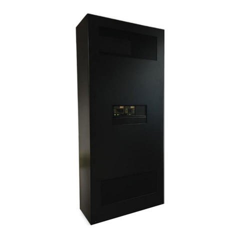
Baldwin Boxall VIGIL ECLIPSE User manual

Baldwin Boxall Communications Ltd.
Wealden Industrial Estate, Farningham Road
Crowborough, East Sussex, TN6 2JR
Telephone: 01892 664422 Fax: 01892 663146
Website: www.baldwinboxall.co.uk
Email: mail@baldwinboxall.co.uk
C O M M U N I C A T I O N S
IBVE
Issue 6 14/07/2004
ECR 1597
VIGIL ECLIPSE
(Compact Software Version COMP4)
Integrated Voice Alarm System
Installation and Operating
Instructions

- 2 -
Issue 6
INDEX
2 ……… Index
3 ……… General Description
4 ……… Mounting Instructions
5 - 6 ……... Installation Instructions
7 - 9 ……… Terminations and Connections
10 ……… Typical Connection Diagram
Attachment 1 ……… BVCOM Instruction Manual
Attachment 2 ……… BVSMP Instruction Manual
Attachment 3 ……… BV440M Instruction Manual
Attachment 4 ……… BV220 Instruction Manual
Attachment 5
Attachment 6
………
………
BV120D Instruction Manual
BV050Q Instruction Manual
Attachment 7 ……… BEL1 Instruction Manual
Attachment 8 ……… Microphone Instruction Manual
Note Attachments supplied depending on system configuration.

- 3 -
Issue 6
GENERAL DESCRIPTION
The VIGIL Eclipse is a purpose-built wall-mountable Voice Alarm or Public Address system.
It boasts simple design that enables straightforward installation and commissioning, along
with facilities to connect with most leading Fire Alarm Panels via the unique internal Fire
Alarm Interface.
The VIGIL Eclipse uses the versatile VIGIL Compact along with the VIGIL amplifiers and
BVSMP (power supply/charger) products and is fully BS5839 part 8 compliant. The VIGIL
Eclipse is available in various combinations that can handle up to four dual circuit zones.
The whole system is wall mountable, completely stand alone and compact in design
measuring only H856 x W556 x D364 mm.
It is recommended that the unit be fitted in a well-ventilated area using the Wall Mounted
Bracket supplied.
The system is powered by a 230V AC 50-60Hz power supply with internal battery backup.
The VIGIL Eclipse is supplied with the necessary number of BEL1 end of line monitoring
devices to provide full monitoring.
Front Panel View
of Eclipse
FIG 1
C O M M U N I C A T I O N S
+ + +
1
2
1
2
1
2
3
4
5
6
7
8
1
2
1
2
1
2
1
29
SELECT
BGM
PAGEMICMESSAGEFIREMIC
MONITOR
HEALTHY
COMMON
FAUL T
FAULTACCEPT LAMPTEST
VOLUMETREBLEBA SS
RESTART
FAUL T
RESET
PROCESSOR
DATA LINK PSUAMP/LINE
FAUL T
FIREMIC MESSAGE
BASIC OPERATING INSTRUCTIONS
SILENCE FAULT BUZZER.
Pres s fau lt ac c ep t butt o n.
Buzz er will si le nce .
Fault indicator will illuminate continuousl
y
.
Call engineer.
FAULT.
Fault LEDs will illuminate, buzzer will sound.
ROU TINE CHE CK S.
Check
g
reen health
y
LED in dicat or “ON”.
Lamp test.
Weekl
y
checks as recommended within BS5839 Part8.
HEA LTHY.
Green LED indicators illuminated.
Silence alarms viafire detec tion equipment only.
FIRE.
system wi ll automatica lly
go into fire m ode on ins truction from
the detection equipment.
ECLIPSE
www.baldwi nb ox al l.co. uk

- 4 -
Issue 6
MOUNTING INSTRUCTIONS
When delivered from the factory, the Eclipse will be supplied on a pallet with a Wall Mounting
Bracket, and depending on the version with Amplifier frames, Microphones (if ordered),
batteries, and BEL1 modules packed separately.
The mounting bracket should be fixed to wall first using suitable bolts for the required
loading. (Centres shown in fig below). The Eclipse then can be fixed on to the mounting
bracket using the 10mm nuts and washers supplied.
Care must be taken to ensure that the wall is strong enough to support the unit, which when
assembled can weigh up to approximately 75KG without batteries.
Diagram Showing Hole
Centres For Mounting
Bracket.
FIG 2
There are a number of ‘knock-outs’ along the top of the box for cable entry, and two in the
base when external batteries are used.
It should be noted that when used for PA only the system is not supplied with any batteries.
It is recommended that the unit is fitted to the wall before the amplifier mainframe(s) and
batteries are installed.
850.0
750.0
710.0
660.0
140.0
90.0
50.0
.0
550.0
529.0
500.0
50.0
21.0
.0
A
A
A
A
A
A
A
A
OUTLINE OF ECLIPSE BOX
OUTLINE OF WALL MOUNTING BRACKET
“A” INDICATES FIXING
POSITIONS TO WALL

- 5 -
Issue 6
INSTALLATION INSTRUCTIONS
Mainframe Assembly
Fit mainframe(s) into Eclipse and connect up as indicated on all cable looms.
Make sure flying lead from mainframe power loom is connected to BVSMP chassis earth
point.
Microphone(s) Installation
Connect suitable (i.e. fire resistant) cable from the microphone(s) to the connections on the
Termination Board inside the Eclipse.
Refer to the relevant Instruction Manuals for connection details of each specific Microphone
type and pages 7-9 of this manual for terminations inside the Eclipse.
Note : When using Fire Microphones (e.g. BFM01 / 04 etc) ensure any unused Zone Select
Outputs are linked to “+VE REF” on the connector block inside the microphone box.
This prevents incorrect fault indications.
Also ensure that for any unused “Fire Microphone Zone Select Lines” the relevant DIL
Switch (SW2.X) on the Termination Board is set to “ON”. See Fig 3 for further details.
Loudspeaker Connections
Ensure all loudspeaker connections are made using suitable cable for the installation. This
includes adequate power rating and for VA installations the cable must be fire resistant.
When BEL1 End of Line Surveillance modules are used the Earth Return from each BEL1
must be connected to the relevant 0V connection on the Termination Board.
Power Up
Remove battery fuses from fuse box and then install batteries into Eclipse. Connect mains to
Eclipse and power on.Refit battery fuses in fuse box.
Setting up the Line Surveillance
The BVCOM can monitor up to 8 (plus one reserve) line outputs. To prevent incorrect fault
indications any unused “Amp/line fault inputs” should have the relevant switch (DIL SW1.X)
on the Termination Board set to “ON”. See Fig 4 for further details.
Set DIL Switch(SW1) to on for Continuous Surveillance mode. See Fig 4 for further details.
Adjust each pre-set in turn through the “Cut Out” in BVCOM lid to produce a 10V surveillance
signal on the relevant zone (measured on the 100V loudspeaker line). See Fig 5 for details.
If there are no line faults all Amp/Line fault indicators on the front panel of the Eclipse should
be extinguished.
Return DIL Switch (SW1) to ‘OFF’ to set the surveillance to intermittent mode. Fig 4.
Note The system should always be returned to intermittent surveillance mode once any
setting up or maintenance has been completed.
Sending out the surveillance signal once every minute instead of continuously minimises the
power consumption of the system, which increases battery standby time and reduces the
heat generated by the power amplifiers.

- 6 -
Issue 6
INSTALLATION INSTRUCTIONS Continued
Switch Any Unused
Fire Mic Select
Lines To ‘ON’.
FIG 3
Switch To ‘ON’ For
Continuous Surveillance.
Switch Any Unused
Line Fault Inputs
To ‘ON’.
FIG 4
Fig 5

- 7 -
Issue 6
TERMINATIONS AND CONNECTIONS
Termination
Board
Function Description Compact
Terminal
1 FM 1 +24V +24V @ 0.5A max via resettable fuse F1 P1 pin10
2 FM 1 Busy Closes to 0V if any zone is in use P1 pin 9
3 FM 1 Access All Close to 0V via 1k2 to call all zones P1 pin 8
4 FM 1 Zone 4 select Close to 0V via 1k2 to call zone 1 P1 pin 7
5 FM 1 Zone 3 select Close to 0V via 1k2 to call zone 2 P1 pin 6
6 FM 1 Zone 2 select Close to 0V via 1k2 to call zone 3 P1 pin 5
7 FM 1 Zone 1 select Close to 0V via 1k2 to call zone 4 P1 pin 4
8 FM 1 Ground 0V P1 pin 3
9 FM 1 Audio line - (balanced line input P1 pin 2
10 FM 1 Audio line + 80 mV @ 80K ohms) P1 pin 1
11 FM 2 +24V +24V @ 0.5A max via resettable fuse F2 P2 pin10
12 FM 2 Busy Closes to 0V if any zone is in use P2 pin 9
13 FM 2 Access All Close to 0V via 1k2 to call all zones P2 pin 8
14 FM 2 Zone 4 select Close to 0V via 1k2 to call zone 4 P2 pin 7
15 FM 2 Zone 3 select Close to 0V via 1k2 to call zone 3 P2 pin 6
16 FM 2 Zone 2 select Close to 0V via 1k2 to call zone 2 P2 pin 5
17 FM 2 Zone 1 select Close to 0V via 1k2 to call zone 1 P2 pin 4
18 FM 2 Ground 0V P2 pin 3
19 FM 2 Audio line - (balanced line input P2 pin 2
20 FM 2 Audio line + 80 mV @ 80K ohms) P2 pin 1
21 PM 1 +24V +24V @ 0.5A max via resettable fuse F3 P3 pin 8
22 PM 1 Busy Closes to 0V if any zone is in use P1 pin 9
23 PM 1 Zone 4 select Close to 0V to call zone 4 P3 pin 7
24 PM 1 Zone 3 select Close to 0V to call zone 3 P3 pin 6
25 PM 1 Zone 2 select Close to 0V to call zone 2 P3 pin 5
26 PM 1 Zone 1 select Close to 0V to call zone 1 P3 pin 4
27 PM 1 Ground 0V P3 pin 3
28 PM 1 Audio line - P3 pin 2
29 PM 1 Audio line + P3 pin 1
30 PM 2 +24V +24V @ 0.5A max via resettable fuse F4 P4 pin 8
31 PM 2 Busy Closes to 0V if any zone is in use P1 pin 9
32 PM 2 Zone 4 select Close to 0V to call zone 4 P4 pin 7
33 PM 2 Zone 3 select Close to 0V to call zone 3 P4 pin 6
34 PM 2 Zone 2 select Close to 0V to call zone 2 P4 pin 5
35 PM 2 Zone 1 select Close to 0V to call zone 1 P4 pin 4
36 PM 2 Ground 0V P4 pin 3
37 PM 2 Audio line - P4 pin 2
38 PM 2 Audio line + P4 pin 1

- 8 -
Issue 6
TERMINATIONS AND CONNECTIONS Continued
Termination
Board
Function Description Compact
Terminal
39 BGM Zone 4 select ( Close to 0V to access or P5 pin 7
40 BGM Zone 3 select via 4k7 potentiometer P5 pin 6
41 BGM Zone 2 select if remote volume control P5 pin 5
42 BGM Zone 1 select Is required ) P5 pin 4
43 BGM Ground 0V P5 pin 3
44 BGM Audio line - P5 pin 2
45 BGM Audio line + P5 pin 1
46 BUSY Zone 1 busy Closes to 0V if zone 1 is in use P7 pin 1
47 BUSY Zone 2 busy Closes to 0V if zone 2 is in use P7 pin 2
48 BUSY Zone 3 busy Closes to 0V if zone 3 is in use P7 pin 3
49 BUSY Zone 4 busy Closes to 0V if zone 4 is in use P7 pin 4
50 BUSY Common busy Closes to 0V if any zone is in use P7 pin 5
51 Link to unused fire microphone select inputs P7 pin 7
52 Surv Sync Close to 0V for continuous surveillance sync. P7 pin 8
53 F/P Evac zone 1 + P8 pin 1
54 F/P Evac zone 1 – ( Sounder circuit interface with internal P8 pin 2
55 F/P Evac zone 2 + end of line Resistors. Reverse polarity P8 pin 3
56 F/P Evac zone 2 - for alarm condition. + - shown for the active P8 pin 4
57 F/P Evac zone 3 + i.e. alarm condition. ) P8 pin 5
58 F/P Evac zone 3 – P8 pin 6
59 F/P Evac zone 4 + ** See note below re EOL resistor values ** P8 pin 7
60 F/P Evac zone 4 – P8 pin 8
61 F/P Reset + P9 pin 7
62 F/P Reset - P9 pin 8
63 F/P Alert all + P9 pin 5
64 F/P Alert all - P9 pin 6
65 F/P Aux O/P Closes to 0V if either fire mic or alarm is in use P9 pin 4
66 F/P Common fault relay output n/o P9 pin 1
67 F/P Common fault relay output common P9 pin 2
68 F/P Common fault relay output n/c P9 pin 3
69 RS 485 data +
70 RS 485 data –
71 Ground 0V
72 Ground 0V
Note The total End Of Line resistor value is a combination of two resistors in series - one is
fitted on the Termination Panel and the other is fitted inside the BVCOM.
By Default, the resistor fitted inside the BVCOM is 2K2.
For values larger than 2K2, the resistor on the termination panel should be changed
(i.e. fitting a 2K7 on the panel would give approximately 5K overall).
For values smaller than 2K2 the resistor on the termination panel should be linked out
and the resistor in the BVCOM changed to the required value.

- 9 -
Issue 6
TERMINATIONS AND CONNECTIONS Continued
Termination
Board
Function Description
AMP1 O/P 100V line loudspeaker output 1
AMP1 0V Earth for BEL1
AMP1 O/P 100V line loudspeaker output 1
AMP2 O/P 100V line loudspeaker output 2
AMP2 0V Earth for BEL1
AMP2 O/P 100V line loudspeaker output 2
AMP3 O/P 100V line loudspeaker output 3
AMP3 0V Earth for BEL1
AMP3 O/P 100V line loudspeaker output 3
AMP4 O/P 100V line loudspeaker output 4
AMP4 0V Earth for BEL1
AMP4 O/P 100V line loudspeaker output 4
AMP5 O/P 100V line loudspeaker output 5
AMP5 0V Earth for BEL1
AMP5 O/P 100V line loudspeaker output 5
AMP6 O/P 100V line loudspeaker output 6
AMP6 0V Earth for BEL1
AMP6 O/P 100V line loudspeaker output 6
AMP7 O/P 100V line loudspeaker output 7
AMP7 0V Earth for BEL1
AMP7 O/P 100V line loudspeaker output 7
AMP8 O/P 100V line loudspeaker output 8
AMP8 0V Earth for BEL1
AMP8 O/P 100V line loudspeaker output 8
LLive Mains Input )
EEarth Mains Input ) Max 1400 VA, fuse at 13A
NNeutral Mains Input )
The above termination list should be used in conjunction with the relevant wiring diagrams
found in their respective Operating Instruction Manual.
Low Volta
g
e Directive
73/23/EEC as amended
by 93/68/EEC
EMC Directive
89/336/EEC as amended
by 92/31/EEC and 93/68/EEC
Applies onl
y
when the items
are correctl
y
fitted and operated
in or with products of our
manufacture and are installed
in a recommended enclosure

- 10 -
Issue 6
Typical Connection Diagram For A Four Zone VA System
MUSIC FROM CD
CASSETTE ETC
PRIORITY 7
LINE LEVEL
OUTPUT
+20 - 30V
BUSY
ACCESS
0V
CALL ALL
+ REF
ZONE 4
ZONE 3
ZONE 2
ZONE 1
FIRE MICROPHONE 1
PRIORITY 1
ZONAL
BFM04
LINE LEVEL
OUTPUT
+20 - 30V
BUSY
ACCESS
0V
CALL ALL
+ REF
ZONE 4
ZONE 3
ZONE 2
ZONE 1
FIRE MICROPHONE 2
PRIORITY 2
BFM04
BASM1
IF M USIC IS NOT
REQUIRED ON A ZONE
DO NOT CONNECT
ITS ACCESS TERMINAL
REMOTE MUSIC
VOLUME CONTROLS
MS2V
ZONE 1
ZONE 2
ZONE 3
ZONE 4
BMS25
22
18
19
20
BUSY
+24V
0V
0V
O/P
O/P
ZONE 4
ZONE 3
ZONE 2
ZONE 1 1
2
3
4
16
17
PAGE MICROPHONE 1
PRIORITY 5
ZONAL
BDM304
BMS25
22
18
19
20
BUSY
+24V
0V
0V
O/P
O/P
ZONE 4
ZONE 3
ZONE 2
ZONE 1 1
2
3
4
16
17
ZONAL
BDM304
PAGE MICROPHONE 2
PRIORITY 6
1
2
3
4
5
6
7
8
9
10
11
12
1
2
3
4
5
6
7
8
9
10
11
12
AMP8
ZONE1
46
47
48
49
50
51
52
53
54
55
56
57
58
59
60
61
62
63
64
65
66
67
68
69
70
71
72
S4
S3
S2
S1
COM
UN. FM
SEL
SURV
SINC
+
-EVAC
Z1
+
-EVAC
+
-EVAC
+
-EVAC
Z2
Z3
Z4
+
-
+
-
RSET
RSET
ALT
ALT
AUX O/P
NC
W
NO
BEL1
LINE
LINE
GND
CCT A
CCT B
CCT A
CCT B
CCT A
CCT B
CCT A
CCT B
ZONE2
ZONE3
ZONE4
S4
S3
S2
S1
0V
I/P
I/P
39
40
41
42
43
44
45
+24V
BUSY
ALL
S4
S3
S2
S1
0V
I/P
I/P
+24V
BUSY
ALL
S4
S3
S2
S1
0V
I/P
I/P
1
2
3
4
5
6
7
8
9
10
11
12
13
14
15
16
17
18
19
20
+24V
BUSY
S4
S3
S2
S1
0V
I/P
I/P
21
22
23
24
25
26
27
28
29
+24V
BUSY
S4
S3
S2
S1
0V
I/P
I/P
30
31
32
33
34
35
36
37
38
1
2
3
4
5
7
9
10
11
12
1
2
3
4
5
7
9
10
11
12
THESE NUMBERS REFER
TO CONNECTIONS ON
BFM01 & BFM04 MICROPHONES
1
2
3
4
16
18
17
22
20
1
2
3
4
16
18
17
22
20
THESE NUMBERS REFER
TO CONNECTIONS ON BMS25
RS485
RS485
0V
0V
OUTPUTS
O/P
O/P
0V
BEL1
LINE
LINE
GND
BEL1
LINE
LINE
GND
BEL1
LINE
LINE
GND
BEL1
LINE
LINE
GND
BEL1
LINE
LINE
GND
BEL1
LINE
LINE
GND
BEL1
LINE
LINE
GND
EVACUATE Z1
EVACUATE Z4
EVACUATE Z3
EVACUATE Z2
RESET
ALERT
SOUNDER
CIRCUITS
BUSY
COMMON
OUTPUTS
FAU LT
ECLIPSE
TERMINATION
BOARD
O/P
O/P
0V
AMP7
O/P
O/P
0V
O/P
O/P
0V
AMP6
AMP5
O/P
O/P
0V
O/P
O/P
0V
O/P
O/P
0V
O/P
O/P
0V
AMP4
AMP3
AMP2
AMP1
ZONE 1-4
COM MON &
FIRE PANEL
Table of contents
Other Baldwin Boxall Security System manuals