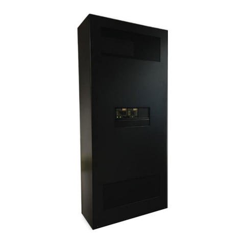
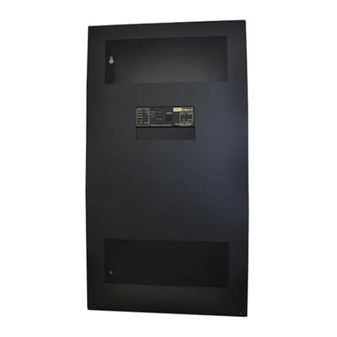
Baldwin Boxall VIGIL3 User manual

VIGIL3 Voice Alarm
Overview, Architecture and
Configuration
Manual name: VIGIL3 Overview, Architecture & Configuration
Issue: 2
ECR: 4494
Date of issue: December 2021

VIGIL3 Voice Alarm
Overview, Architecture and Configuration
ii VIGIL3 Overview, Architecture & Configuration issue 2
© December 2021 Baldwin Boxall Communications Limited
Wealden Industrial Estate
Farningham Road
Crowborough
East Sussex
TN6 2JR
UK
Telephone: +44 (0)1892 664422
Email: [email protected].uk
Website: http://www.baldwinboxall.co.uk
This equipment has been designed and manufactured to conform to both CE &
UKCA requirements
Failure to use the equipment in the manner described in the product literature
will invalidate the conformity.
A “Declaration of Conformity” statement and a “Declaration of Performance” is
available on request.

VIGIL3 Voice Alarm
Overview, Architecture and Configuration
VIGIL3 Overview, Architecture & Configuration issue 2 iii
Amendment Record ___________________________________ v
Proprietary Notice ____________________________________ v
Safety Information ___________________________________ vi
Comments_________________________________________ vi
Introduction
Scope _____________________________________________1
VIGIL3 Voice Alarm Features ____________________________1
VIGIL3 Voice Alarm Description __________________________2
Architecture
VIGIL3 Module Connections _____________________________5
Centralised vs Distributed / Networked Systems ______________6
Audio Input and Output Numbering _______________________8
Microphones ________________________________________8
Audio Priorities _____________________________________ 10
Voice Alarm (VA) Active Indication _______________________ 11
Fire Panel Inputs_____________________________________ 11
Cause and Effect Rule Engine____________________________ 11
Power Distribution___________________________________ 13
Real Time Clock_____________________________________ 14
Fault Indication
Configuration

VIGIL3 Voice Alarm
Overview, Architecture and Configuration
iv VIGIL3 Overview, Architecture & Configuration issue 2

VIGIL3 Voice Alarm
Overview, Architecture and Configuration
VIGIL3 Overview, Architecture & Configuration issue 2 v
AMENDMENT RECORD
Change Note
Number
Nature of Amendment Date of
Amendment
N/A Initial release: Issue 1 Feb 2020
ECR4494 Issue 2: Correct OS1 and OS2 max distances Dec 2021
PROPRIETARY NOTICE
All data and information contained within this manual is of a
proprietary nature with the exclusive title to the same held by
Baldwin Boxall Communications Limited. The possession of this
manual and the use of the information is, therefore, restricted
only to those persons duly authorised by Baldwin Boxall
Communications Limited.
Do not reproduce, transcribe, store in a retrieval system or
translate into any language, any part of this manual without the
prior permission of Baldwin Boxall Communications Limited.
In the interest of continual product development, Baldwin Boxall
Communications Limited reserves the right to make changes to
product specification without notice or liability. Use of Baldwin
Boxall Communications Limited products as critical components
in life support systems is not authorised except with express
written approval from Baldwin Boxall Communications Limited.

VIGIL3 Voice Alarm
Overview, Architecture and Configuration
vi VIGIL3 Overview, Architecture & Configuration issue 2
SAFETY INFORMATION
Personnel who install, maintain or repair this equipment must
read the safety information below before starting work.
Voltages in excess of 30 Volts RMS or 50 Volts DC are considered
Hazardous and in certain circumstances can be lethal.
If Functional Testing, Maintenance, or Repair is to be completed
with the Mains Power (and/or battery backup) connected then
this should only be undertaken by personnel who are fully aware
of the danger involved and who have taken adequate precautions
and training.
This Manual contains Warnings, Cautions and Notes.
War nings describe potential threats to health or life, e.g.
WARNING
Before attempting to remove this component, ensure the Mains
Power Supply and Battery Backup have been disconnected.
Cautions describe potential threats to the equipment, e.g.
CAUTION
Notice must be taken of all cautions.
If a Caution is ignored the equipment may be damaged.
CAUTION: ELECTRO-STATIC SENSITIVE DEVICES
Observe the relevant precautions for the protection of Electro-
static Sensitive Devices when handling this equipment.
Notes are statements that are useful to the user in the context of
a particular section of the manual, e.g.
NOTE: Do not speak into the microphone until the "Speak Now" LED is
illuminated.
COMMENTS
Comments regarding the content of this manual are welcome and
should be addressed to hello@baldwinboxall.co.uk.
!!!

VIGIL3 Voice Alarm
Overview, Architecture and Configuration
VIGIL3 Overview, Architecture & Configuration issue 2 1
1Introduction
1.1 SCOPE
This document is an overview of a VIGIL3 EN54 Approved Voice
Alarm System.
1.2 VIGIL3 VOICE ALARM FEATURES
The Vigil Voice Alarm System offers the following features;
• Up to 800 audio outputs
• Up to 400 audio inputs
• Up to 400 RS485 control ports
• 64 simultaneous site wide audio channels
• 254 fully monitored voice alarm messages (8GB storage in
.wav format)
• Site wide configuration from a single location
• User customisable graphical touch screen control
• Rules based Cause & Effect / Phased Evacuation engine
• Fully modular and expandable
• Built in fault tolerant networking

VIGIL3 Voice Alarm
Overview, Architecture and Configuration
2VIGIL3 Overview, Architecture & Configuration issue 2
• Up to 24 band parametric equalisation
• Up to 1s audio delay
1.3 VIGIL3 VOICE ALARM DESCRIPTION
The VIGIL3 Voice Alarm range consists of a family modules that
when combined form a complete Voice Alarm and Public Address
System.
The following VIGIL3 modules are available;
• Amplifiers
• BV75D - 2 x 75W Amplifier Blocks
• BV150D -2 x 150W Amplifier Blocks
• BV300D - 2 x 300W Amplifier Blocks
• BV75Q - 4 x 75W Amplifier Blocks
• BV150Q - 4 x 150W Amplifier Blocks
• Battery Charger
• BVMBC - 10A battery charger
• Audio Routing
• BV3AOM8 - 8 Way Audio Output Module
• BV3AIM2 - 2 Way Audio Input Module
• BV3AIM4 - 4 Way Audio Input Module
•Networking
• BV3CIF - Copper Networking Interface
• BV3FIFM - Multimode Fibre Networking Interface
• BV3FIFS - Singlemode Fibre Networking Interface
• Interfacing
• BV3FPI - BV3AOM8 Fire Panel Termination Interface
• BVRDFPI - Fire Panel Interface
• BVRDCI - General Purpose I/O Interface
• Speaker Line Monitoring

VIGIL3 Voice Alarm
Overview, Architecture and Configuration
VIGIL3 Overview, Architecture & Configuration issue 2 3
• BVRDACO - 10 way AC line monitoring module with
changeover
• BVRDNCO - 10 way AC line monitoring module
• BVRDADC - 10 way DC line monitoring module with
changeover
• BV3ADIM / BV3ADIS - Up to 10 way DC line
monitoring modules with changeover and A/B isolation
• BVLAM - 8 Way Impedance Line monitoring module
• Cooling and Power Distribution
• BV3MDPEFM - Exhaust Fan Module - required for all
systems using mains distribution panels below
• BV3MDP05F - 5 way mains distribution and fans,
supports up to 5 VIGIL3 amplifiers (2 x main frames)
• BV3MDP10F - 10 way mains distribution and fans,
supports up to 10 VIGIL3 amplifiers (4 x main frames)
• BV3EFM - Single main frame standalone cooling, no
power distribution
• Microphones
• BVRDTSM - Touchscreen voice alarm control
microphone
• BVRDTSMMON - External monitor for BVRDTSM
allowing user customisation of graphical interface
• BFM401-408 - Single to 8 way Fire Microphones
• BDM401-416 - Single to 16 way Paging Microphones
NOTE: BVRD Microphones are not supported by VIGIL3 Systems.
Please refer to the individual Hardware Installation Guides for
specific information about the above modules.

VIGIL3 Voice Alarm
Overview, Architecture and Configuration
4VIGIL3 Overview, Architecture & Configuration issue 2

VIGIL3 Voice Alarm
Overview, Architecture and Configuration
VIGIL3 Overview, Architecture & Configuration issue 2 5
2 Architecture
2.1 VIGIL3 MODULE CONNECTIONS
The VIGIL3 Voice Alarm system is completely modular in nature.
Audio Input and Output modules are connected together in a
large Ethernet based loop (no switches required) to form a single
Voice Alarm Control and Indicating (VACIE) system.
Amplifiers are connected to the Audio Outputs of the BV3AOM8
via CAT5 patch leads and audio inputs are connected to BV3AIM2
or BV3AIM4 modules.
BV3AOM8 modules are mounted within amplifier main frames
so the fault indications are visible from the front and BV3AIM2/
4 modules are mounted on DIN Rail at the rear of the rack for
easy site wiring termination.
NOTE: BV3AOM8 amd BVMBC modules do not need to be located within
the cooling air flow and can be mounted in seperate mainframes to the
amplifiers if required.
CAN Bus Modules (BVRDCI, BVRDACO, BV3MDP10F etc.)
are connected in a daisy chain configuration to a BV3AOM8.
NOTE: Speaker line monitoring CAN bus modules (BVRDACO,
BVRDNCO etc) must be connected to the BV3AOM8 serving those speaker
circuits.

VIGIL3 Voice Alarm
Overview, Architecture and Configuration
6VIGIL3 Overview, Architecture & Configuration issue 2
Please see a typical single rack VIGIL3 Voice Alarm System Block
Diagram below.
Figure 2.1 — Typical single rack VIGIL3 system
2.2 CENTRALISED VS DISTRIBUTED /
NETWORKED SYSTEMS
VIGIL3 systems can be realised as centralised (single rack) or
decentralised (networked systems).
For centralised systems the Ethernet loop is completed using
CAT5 patch leads. For networked systems VIGIL3 networking
modules are used for rack to rack connections;

VIGIL3 Voice Alarm
Overview, Architecture and Configuration
VIGIL3 Overview, Architecture & Configuration issue 2 7
• BV3CIF - Copper connections, CAT5 fire rated connection,
Max 100m
• BV3FIFM - Multimode fibre connections, Duplex SC
Termination, fire rated fibre, Max 2KM
• BV3FIFS - Singlemode fibre connections, Duplex SC
Termination, fire rated fibre, maximum distance for OS1 is
2KM, and for OS2 is 4KM
Please see the VIGIL3 Networking Installation Manual for more
information regarding these modules.
Regardless of the type of system all VIGIL3 Audio modules are
connected in a single fault tolerant Ethernet loop.
NOTE: It is important to maintain the Network Out -> Network In
convention throughout a VIGIL3 system. Connecting a Network In to a
Network in or a Network Out to a Network Out will result in a non-
operable system.

VIGIL3 Voice Alarm
Overview, Architecture and Configuration
8VIGIL3 Overview, Architecture & Configuration issue 2
2.3 AUDIO INPUT AND OUTPUT
NUMBERING
VIGIL3 systems can be realised up to a maximum of 800 outputs
and 400 inputs. Input and output numbering is dependent on the
ID of the BV3AOM8 or BV3AIM2/4 module. The following
tables illustrate the input and output numbering conventions used
in a VIGIL3 system;
Table 2.1 — VIGIL3 Output Numbering
Unit ID Outputs
00 1-8
01 9-16
02 17-24
etc
Table 2.2 — VIGIL3 Input Numbering
Unit ID Inputs
00 1-4
01 5-8
02 9-12
etc
NOTE: VIGIL3 inputs are grouped in 4’s, if BV3AIM2 modules are used
some inputs will not be available e.g. BV3AIM2 (ID00) will have inputs
1&2 and BV3AIM2 (ID01) will have inputs 5&6
Please see the BV3AOM8 and BV3AIM2/4 installation manuals
for details of ID setting.
2.4 MICROPHONES
VIGIL3 supports both native VIGIL3 microphones (BVRDTSM)
and legacy Vigil 2 (BDM & BFM) microphones.
Each BV3AIM2/4 audio input has a corresponding RS485 control
port which must be configured correctly (Protocol in use, BAUD
rates etc.)

VIGIL3 Voice Alarm
Overview, Architecture and Configuration
VIGIL3 Overview, Architecture & Configuration issue 2 9
For BVRDTSM microphones the mapping of buttons on the
screen to system audio outputs is performed via the BVRDTSM
configuration.
For BDM/BFM microphones the mapping of button to output is
performed in the VIGIL3 Configuration (BDM/BFM Access
Profile). The configuration of the physical microphone is identical
meaning that Vigil 2 microphones can be replaced without
altering any configuration settings.
In both cases any button can correspond to any combination of
outputs between 1 and 800.
NOTE: Vigil 2 16 way microphones require 2 x RS485 ports in order
access all 16 buttons. Therefore a BV3AIM4 can only support 2 x Vigil 2
16 way microphones.

VIGIL3 Voice Alarm
Overview, Architecture and Configuration
10 VIGIL3 Overview, Architecture & Configuration issue 2
Please see below for a table of the required BDM/BFM
Microphone configuration (stored in the BDM/BFM
microphone).
Table 2.3 — Vigil 2 BDM/BFM required configuration
Config Item Required Setting
Speak Now Delay As required to allow chime to finish
Microphone Address 5
Audio Input Channel Input 5a
Number of routers 1
Mic Surveillance Mic Capsule/Audio/Data*1
Message Mode All Call
Protocol Type Type 3*2
Poll Rate 1.0
Baud Rate 9600*2
Microphone Type As required depending on microphone type
Single Zone, 4/8 Zone or 16 Zone
Repeat Transmission 2
Busy Disable (from) 10
Busy Disable (to) 11
VA Input Active Input 1a to 2a
VA Message Active Message 1 to 2
NOTE: *1 If fault buzzer is not required the Mic Surveillance can be set
to Mic Capsule/Audio/Data/No Buzzer
NOTE: *2 Matching configuration must be present in the BV3AIM2/4
module.
2.5 AUDIO PRIORITIES
VIGIL3 systems support a total of 254 priorities that can be
allocated to audio inputs and DVA messages. Priority 1 is the
highest and 254 is the lowest. A higher priority input will
override a lower priority input.
If 2 inputs with the same priority are attempted to be routed to
the same output the system operates on a first come first served
basis.

VIGIL3 Voice Alarm
Overview, Architecture and Configuration
VIGIL3 Overview, Architecture & Configuration issue 2 11
Each audio input has 2 priorities associated with it that
correspond to key turned (Emergency Mode) or key not turned
(Paging) modes.
2.6 VOICE ALARM (VA) ACTIVE INDICATION
VA Active indication is performed based on priority. Any input or
message routed to any output with a Priority between 1 and 64
will cause all system VA Active indicators to illuminate.
2.7 FIRE PANEL INPUTS
Fire panel inputs in a VIGIL3 system can be connected to either
BVRDFPI CAN bus Fire Panel Interface modules or to BV3FPI
Fire Panel Interface Modules.
Facilities are provided for the connection of Fire Panel specific
EOL resistors to enable the fire panel to monitor the connection
to the VIGIL3 System.
Fire Panel inputs can be either continuous or pulsing to indicate
Alert and Evacuate conditions.
2.8 CAUSE AND EFFECT RULE ENGINE
All external triggering (i.e. by a Fire Panel) of message playback
or route setting is controlled by the VIGIL3 Cause and Effect
engine.
The Cause and Effect engine is made up a series of configurable
rules which have a “Cause” (e.g. FPI Input) and an “Effect” (e.g.
Start message playback). Rules act upon Output Sets each of
which can contain any combination of outputs from 1-800.
Each BV3AOM8 can manage up to;
• 200 Individual Rules
• 50 Output Sets

VIGIL3 Voice Alarm
Overview, Architecture and Configuration
12 VIGIL3 Overview, Architecture & Configuration issue 2
Rules can be triggered by;
• A message being triggered or removed from an output
• A route being triggered or removed from an output
• A BVRDCI Control Output Changing State
• A BVRDFPI or BV3FPI input
• A BVRDCI Control Input
• By a countdown timer started by another Rule
• At a specific time
•Hourly
•Daily
• Weekdays only
• Weekends only
• Weekly
• Monthly
• Annually
The effect of a rule being triggered can be;
• Set a volume control
• Start or Stop a message to an Output Set
• Set a route or clear a route from an Input to an Output Set
•SetorClearaBVRDCI Control Output
• Adjust the system time
• Start a countdown timer that then triggers another Rule on
expiry
Cause and Effect rules should be created in order to push “Effects”
out to other BV3AOM8 modules. This will ensure that in the
event of catastrophic system failure (i.e. due to fire damage) the
remaining system will continue to function as expected.

VIGIL3 Voice Alarm
Overview, Architecture and Configuration
VIGIL3 Overview, Architecture & Configuration issue 2 13
2.9 POWER DISTRIBUTION
VIGIL3 implements a propriety Power Over Ethernet (POE)
mechanism in order to simplify cabling during rack design and
build.
Power is carried on spare conductors of the Ethernet cable
meaning that not all modules require a separate power
connection.
Sources of Power In a VIGIL3 System
• A BVMBC connected to a BV3AOM8
• 24V DC connected to a BV3AIM2/4 Audio Input Module
NOTE: If power consuming equipment i.e. Microphones are connected to
a BV3AIM2/4 module then Power must be connected to that BV3AIM2/
4 module. Site equipment cannot be powered via POE
NOTE: 24V DC can be as high as 32V when the system is connected to
AC Mains and tracks the battery voltage when running on batteries

VIGIL3 Voice Alarm
Overview, Architecture and Configuration
14 VIGIL3 Overview, Architecture & Configuration issue 2
A device which is connected to Power Source can provide power
to up to 2 devices on each network connection therefore as a rule
of thumb there must be a power source connected as shown in the
diagram below;
Figure 2.2 — VIGIL3 Power Distribution
NOTE: If a BV3AOM8 is to have a VIGIL3 fan controller connected to it
via CAN Bus then this unit must also be connected to a BVMBC due to the
power demands of the fans.
2.10 REAL TIME CLOCK
The VIGIL3 system has a highly accurate RTC subsystem used for
Timed Cause and Effect rules and Time and Date stamping fault
logs hectic.
The time is maintained by all BV3AOM8 modules and is set via
the VIGIL3 Configurator Application.
NOTE: The VIGIL3 system will maintain the time and date as long as it
is powered (either via mains or the backup batteries). If the system is
completely powered down the time and date will need to be set again.
Table of contents
Other Baldwin Boxall Security System manuals