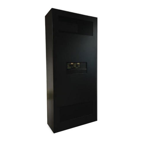
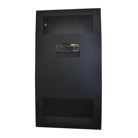
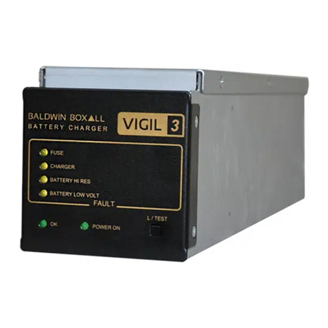
Baldwin Boxall VIGIL BVR20 Manual

Baldwin Boxall Communications Ltd.
Wealden Industrial Estate, Farningham Road
Crowborough, East Sussex, TN6 2JR
Telephone: 01892 664422 Fax: 01892 663146
Website: www.baldwinboxall.co.uk
Email: mail@baldwinboxall.co.uk
C O M M U N I C A T I O N S
IBVR20
08/08/2003
ECR 1500
VIGIL BVR20 - Microdrive
(For use with software issue BVR8.43)
SETUP
INSTRUCTIONS

Page 2 IBVR20 software 8.43.doc Issue 1
CONTENTS
VIGIL BVR20 MICRODRIVE ..................................................................................................3
BVR802 – Quad EPROM based digital message module .......................................................4
BVR20 FRONT PANEL CONTROLS AND INDICATORS.......................................................5
DESCRIPTION OF FRONT PANEL CONTROLS AND INDICATORS....................................6
MAINTENANCE OF THE BVR20 ............................................................................................7
FAULT REPORTING AND STATUS PAGES ..........................................................................8
HOW TO MONITOR EITHER AN INPUT OR OUTPUT CHANNEL SIGNAL ........................11
HOW TO VIEW OR CHANGE AN OUTPUT CHANNEL SETTING.......................................12
HOW TO VIEW OR CHANGE AN INPUT CHANNEL SETTING...........................................16
HOW TO VIEW OR CHANGE SERIAL PORT ADDRESS, BVRM ZONE POSITION, FIRE
PANEL INTERFACE SELECTION AND MESSAGE CONFIGURATION. .............................20
CODES FOR ZONE OUTPUT BARRING .............................................................................23
BVRM DIL SWITCH SETTINGS............................................................................................36

Page 3 IBVR20 software 8.43.doc Issue 1
VIGIL BVR20 MICRODRIVE
The BVR20 (Microdrive) is the heart of the Voice Alarm system that accepts all of the audio
inputs and provides the outputs for the whole voice alarm system. Up to 20 audio inputs can
be routed through to up to 20 outputs (zones) in any configuration. The inputs range from
any microphone or line level source to the emergency messages and background music.
The system is modular, and depending on the system requirements different modules are
plugged into the rear of the BVR20.
BVR20 Modules & Brief description of Functions and Features
Module Function
BVRCPU CPU and PSU card: one per BVR20
BVRI4 Quad line input (each with attenuator, compressor, limiter, 5 band equ & chime
control)
BVR802 Quad Digital message card, accepts up to 4 OPT402 modules
BVRO2 Dual line output card (each with 6 band equ and option socket for further EQ
module)
BVRIO40 40 parallel inputs for zonal access, monitoring, fault i/p & o/p, changeover etc
BVRACO Control interface for faulty amplifier changeover
BVRNCO Control interface for when automatic changeover is not required
BVRCI Control interface for universal zonal access switching, with Ambient noise option
BVRAIO Control interface for Fire Alarm Panel
BVRL20 20 way 3 metre ribbon cable for connecting cards and interface modules
BVRL26 26 way 3 metre ribbon cable for connecting cards and interface modules
The BVR20 provides all of the monitoring functions and displays the system status using a
40 x 2 character LCD display and 5 front panel mounted LEDs.
The unit can be operated in two separate modes depending on the position of the front panel
key-switch. Under ‘Normal’ operating conditions (i.e. the key is not turned) all advanced
functions of the BVR20 are barred to prevent unauthorised changes to the system. The only
options available are monitoring input and output signals through the internal loudspeaker,
and viewing the system status pages which can be scrolled up or down to display the status
of the monitored items in the Voice Alarm system.
If the ‘System Configuration’ key-switch is turned the unit is in System Configuration mode
and all functions of the BVR20 can be changed.
The functionality of the Voice Alarm System can be altered in this mode.
As incorrect use of this mode could prevent an Alarm Condition from being detected
we strongly suggest that this mode is not entered unless the user is fully aware of the
system configuration.
If changes are to be made in this mode please refer to the relevant pages of this manual on
how to achieve the changes required.
To discourage leaving the unit in “System Configuration” mode the key cannot be removed
from the switch until it is returned to the “Normal” position.
When the unit is first powered up, various settings and controls will require setting up in the
“Configuration” Mode. Once these have been set, the internal memory will hold this
information. Should mains and/or battery power loss occur, the settings will remain in the
memory.

Page 4 IBVR20 software 8.43.doc Issue 1
BVR802 – Quad EPROM based digital message module
This card enables four OPT 402 message modules to be fitted allowing up to seven messages to be
stored on one card. It has the following features:-
Three dual messages plus one single message – 7 x 32 seconds in length or four at 64 seconds.
Each message has output attenuation.
Bass, Treble and two mid band controls @ 1KHz & 2.5KHz.
200Hz 12dB/Octave high pass filter.
Aural and visual monitor.
20 sounder circuit opto coupled inputs.
OPT402 CH1 OPT402 CH2 OPT402 CH3 OPT402 CH4
(MESSAGE 1) (MESSAGE 2&3) (MESSAGE 4&5) (MESSAGE 6&7)
EVAC ONLY
SOUNDER CIRCUITS
1 - 10
SOUNDER CIRCUITS
11 - 20
BVR802
ONE CHANNEL SHOWN
+5V+15V
RESETABLE
FUSE
1
2
-
+
-
-
+0dBM
OUTPUT
L/S MON
TREBLE
2K5
1K0
BASS
+15v
MESS START
L/S MON
VOL
+6dB
20 X
OPTO COUPLED
INPUTS
OPT 402
MULTIPLEXER
MEMORY
FAULT
A0
A1
A2
STROBE
AD3
AD4
AD5
+5V
2K2
TO MULTIPLEXER
OPTO COUPLED
INPUTS
CLOCK
DATA
OPT402 Positions on BVR802OPT402 Positions on BVR802OPT402 Positions on BVR802

Page 5 IBVR20 software 8.43.doc Issue 1
BVR20 FRONT PANEL CONTROLS AND INDICATORS
COMPLIES
COMMON
SYSTEM
HEA LTHY
FAULT
FAULT
ACCE PT
FA ULT
RESTART
CPU
CPU
12
45
3
6
789
-+0
BS5839
WITH
PART
8
LAMP TEST
SERIAL INTERFACE
PAGE
PAGE
UP
DOWN
SYSTEM CONFIGURATION
BVR20 MICRODRIVE
AB
C
D
EF
G
HIJ K LM N O PQ
R

Page 6 IBVR20 software 8.43.doc Issue 1
DESCRIPTION OF FRONT PANEL CONTROLS AND INDICATORS
A‘System Healthy’
LED Will illuminate when no faults are detected.
B‘CPU Fault’ LED
If illuminated a critical CPU failure has occurred.
Only Fire Mic 1 ‘All Call’ function will operate as this input
bypasses all CPU control as required by BS5839 pt 8.
C
‘Common Fault’
LEDs
Will flash and a buzzer will sound when a Fault is detected
until “Fault Accept” button (H) is pressed.
After a fault is accepted the buzzer is silenced and the LEDs
remain illuminated until the fault is cleared.
D CPU Restart LED
Will illuminate when CPU Restart (J) button needs to be
pressed. This will occur when the unit is powered up for the
first time, but should extinguish after the restart. Required by
BS5839 pt 8.
E 40 x 2 LCD Display Main display where system status and setup configuration is
shown.
F Loudspeaker Loudspeaker for monitoring input and output signals.
G Buzzer Sounds when a fault is detected, see (C) for more details.
H ‘Fault Accept’ Button Press to accept a fault once detected, see (C) for more
details.
I ‘Lamp Test’ Button
Press to check front panel LED and buzzer operation.
Note: if the system is in a fault condition the green ‘System
Healthy’ LED will not illuminate on a lamp test.
J CPU Restart Button Recessed button that enables the CPU to be restarted, see
(D) for more details.
K Data Entry Keypad Numerical keys for entering and changing data.
L & M ‘Page Up’ / ‘Page
Down’ Buttons
Press to scroll through Status Pages displayed on the LCD
Display.
N‘
Í’ & ‘Î’ Buttons Press to navigate cursor inside Status Pages.
O Volume Control Press to alter volume of monitor Loudspeaker or Headphones.
P Headphone Socket Socket for Headphones to monitor input and output signals. If
Headphones are connected the internal loudspeaker is muted.
Q
‘System
Configuration’
Keyswitch
Key-switch to enable System Configuration.
When enabled all functions of the BVR20 can be modified.
The key cannot be removed in the ‘System Configuration’
position.
R ‘Serial Interface’ Feature not available on this software release.

Page 7 IBVR20 software 8.43.doc Issue 1
MAINTENANCE OF THE BVR20
If a fault is suspected on any of the BVR20 modules, simple substitution with a spare can be
carried out as first-line maintenance. Before removing any module ensure that the two DC
supplies are disconnected by removing the lower 8-way blue plug from the CPU module.
The CPU module BVRCPU – as viewed from the rear – is located at the extreme right hand
side, position 21.
Carefully remove all connectors to the suspected module with a small posi-drive screwdriver,
release the two retaining screws at the rear of the module and, observing electro-static
precautions, carefully remove the module. To replace the module, carefully slide in the new
module, fasten it using the two screws, replace the connectors and now you are ready to
apply power. Please ensure that the correct module has been fitted in the correct position.
The heart of the BVR20 is the CPU module – BVRCPU - which controls all the input and
output routing, together with all monitoring facilities. Please note this module must only be
fitted in position 21, at the extreme right hand side of the BVR20.
As a simple guide to fault finding, should one zone output be faulty then it would be true to
suspect the output card serving that zone – especially if the other channel is operating.
Input modules – BVRI4 - have four inputs, each with a max sensitivity of -20dBm ( 80mV),
which is amplified and presented to the audio bus structure at 0 dBm ( 800mV).
The message module –BVR802 – has the facility for four messages and provides 20 opto
isolated inputs to interface with fire detection panel sounder circuits. Again the signal from
each message is presented to the audio bus at 0dBm. The system monitors the audio output
presented to the first output module and the DC bias present at the output of the digital-to-
analogue converter, which is displayed as a memory fault.
The dual output card –BVR02 – has two line outputs of 0dBm and provides frequency
equalisation and gating from all the 20 input signals. This module also provides volt-free
relay contacts, which change condition when the zone is busy.
On the system there are two signal input/output cards – the BVRIO40 which, in conjunction
with the interface cards – the BVRACO, monitor the external loudspeaker lines using the
BEL1 end of line units. The BVRACO also provides automatic changeover in the event of a
faulty amplifier to a reserve. The module positioned in P18 serves all the ‘A’ circuits, whilst
the one fitted to P19 serves all the ‘B’ circuits. Input signals for the reserve amplifiers are
obtained from output modules plugged into P16 and P17 and automatically, in the event of
an amplifier failure, route the correct source of signals to the relevant reserve amplifier.
All of the BVR20 modules are fed from an unregulated dual supply line and regulation is
provided on each module. The supply input to each card is protected by a poly-switch self-
resettable fuse and, in the case of the CPU, a dual regulator path is provided.
Please note: Under no circumstances remove or replace a module with the power
supply connected.
Should a faulty module be discovered, repair can only be accomplished in an equipped
workshop. Therefore, we recommend that first-line maintenance is carried out by replacing
modules from a spares stock.
If the system has automatic changeover it will be necessary to press the ‘CPU Restart’
on front panel when the faulty amplifier is replaced.

Page 8 IBVR20 software 8.43.doc Issue 1
FAULT REPORTING AND STATUS PAGES
(Available in “normal” mode i.e. without turning the “system configuration” key.)
In normal operation mode this unit indicates the condition of the system via the front panel
display. Under normal - i.e. non-fault - conditions the green healthy indicator will illuminate,
the fault relay will be energised and the sounder will be silent.
A fault is indicated by the flashing yellow “Common Fault” indicators, together with the
sounder, sounding 1 second on, 1 second off. By pressing the “Fault Accept” button the fault
indicator will illuminate continuously and the sounder will be silent. Separate yellow
indicators are used for CPU Fault and CPU Restart. Pressing the “Lamp Test” button checks
all the “Fault” indicators.
Note: Operation of the “Fault Accept” button does not affect the fault output
produced by the relay contacts to external equipment i.e. Fire detection panel.
The various status pages are scrolled up and down with the “Page Up” and “Page Down”
keys.
Faults are shown by “XX” in place of “OK” ,lower case “ok” shows a fault has occurred and
cleared. This is useful to show where intermittent faults have been ,to reset operate key
switch momentarily.
The pages are displayed in the following order:
Page1. Loudspeaker lines 1-10 circuit A.
------------------------------------------
| L/S LINE A|01|02|03|04|05|06|07|08|09|10 |
| FAULTS |XX|OK|OK|OK|OK|OK|OK|OK|OK|OK |
------------------------------------------
E.g. XX indicates there is a fault on loudspeaker circuit 1A.
Page2. Loudspeaker lines 1-10 circuit B.
------------------------------------------
| L/S LINE B|01|02|03|04|05|06|07|08|09|10 |
| NO FAULTS |OK|OK|OK|OK|OK|OK|OK|OK|OK|OK |
------------------------------------------
Page3. Loudspeaker lines 11-20 circuit A.
------------------------------------------
| L/S LINE A|11|12|13|14|15|16|17|18|19|20 |
| NO FAULTS |OK|OK|OK|OK|OK|OK|OK|OK|OK|OK |
------------------------------------------
Page4. Loudspeaker lines 11-20 circuit B.
------------------------------------------
| L/S LINE B|11|12|13|14|15|16|17|18|19|20 |
| NO FAULTS |OK|OK|OK|OK|OK|OK|OK|OK|OK|OK |
------------------------------------------
Page5. Reserve amplifiers.
------------------------------------------
| RESERVE AMPLIFIERS|1 OK|2 OK|3 OK|4 OK |
| NO FAULTS In use|- --|- --|- --|- -- |
------------------------------------------

Page 9 IBVR20 software 8.43.doc Issue 1
Page 5 examples.
------------------------------------------
| RESERVE AMPLIFIERS|1 XX|2 OK|3 OK|4 OK |
| FAULTS In use|- --|- --|- --|- -- |
------------------------------------------
XX indicates that reserve amplifier 1 has a fault.
------------------------------------------
| RESERVE AMPLIFIERS|1 OK|2 OK|3 OK|4 OK |
| NO FAULTS In use|A 01|- --|- --|- -- |
------------------------------------------
Reserve amplifier 1 in use on loudspeaker circuit 1A.
Page6. Emergency microphones.
------------------------------------------
| FIRE MICS | AUDIO 1=OK| ACCESS 1=OK |
| NO FAULTS |2=OK 3=OK 4=OK|2=OK 3=OK 4=OK |
------------------------------------------
Emergency microphones
------------------------------------------
| FIRE MICS | AUDIO 1=OK| ACCESS 1=OK |
| FAULTS |2=XX 3=OK 4=OK|2=OK 3=OK 4=OK |
------------------------------------------
XX indicates that Mic 2 has an audio fault
Page7. Message 1 (evacuate).
------------------------------------------
| MESSAGE 1 EVACUATE|MEMORY|AUDIO|ACCESS |
| NO FAULTS |OK |OK |OK |
------------------------------------------
Page8. Message 2 and 3.
------------------------------------------
| MESSAGE 2 & 3 |MEMORY|AUDIO| ACCESS |
| NO FAULTS |OK |OK |2=OK 3=OK |
------------------------------------------
Page9. Message 4 and 5.
------------------------------------------
| MESSAGE 4 & 5 |MEMORY|AUDIO| ACCESS |
| NO FAULTS |OK |OK |4=OK 5=OK |
------------------------------------------
Page10. Message 6 and 7.
------------------------------------------
| MESSAGE 6 & 7 |MEMORY|AUDIO| ACCESS |
| NO FAULTS |OK |OK |6=OK 7=OK |
------------------------------------------

Page 10 IBVR20 software 8.43.doc Issue 1
Page11. Page microphones 1 to 4 if monitored.
------------------------------------------
| PAGE MICS | AUDIO 1=OK| ACCESS 1=OK |
| NO FAULTS |2=OK 3=OK 4=OK|2=OK 3=OK 4=OK |
------------------------------------------
Page microphones 1 to 4
------------------------------------------
| PAGE MICS | AUDIO 1=OK| ACCESS 1=OK |
| FAULTS |2=XX 3=OK 4=OK|2=OK 3=OK 4=OK |
------------------------------------------
XX indicates that Mic 2 has a audio fault.
Page12. Page microphones 5 to 8 if monitored.
------------------------------------------
| PAGE MICS | AUDIO 5=OK| ACCESS 5=OK |
| NO FAULTS |6=OK 7=OK 8=OK|6=OK 7=OK 8=OK |
------------------------------------------
Page microphones
------------------------------------------
| PAGE MICS | AUDIO 5=OK| ACCESS 5=OK |
| FAULTS |6=OK 7=OK 8=OK|6=OK 7=XX 8=OK |
------------------------------------------
XX indicates that Mic7 has a access fault.
Page13. Noise sensing microphones 1 to 10
------------------------------------------
| NOISE SENS |01|02|03|04|05|06|07|08|09|10|
| NO FAULTS |OK|OK|OK|OK|OK|OK|OK|OK|OK|OK|
------------------------------------------
Page14. Noise sensing microphones 11 to 20
------------------------------------------
| NOISE SENS |11|12|13|14|15|16|17|18|19|20|
| NO FAULTS |OK|OK|OK|OK|OK|OK|OK|OK|OK|OK|
------------------------------------------
Page15. Power supplies to BVR 20 and battery chargers
------------------------------------------
| POWER |BATT/CHARGER|SUPPLY 1|SUPPLY 2 |
| NO FAULTS|OK |OK |OK |
------------------------------------------
Page16.
------------------------------------------
| L/S |OUTPUT ZONE|INPUT SOURCE|VOLUME |
| MONITOR |00 |-- |00 |
------------------------------------------

Page 11 IBVR20 software 8.43.doc Issue 1
HOW TO MONITOR EITHER AN INPUT OR OUTPUT CHANNEL SIGNAL
VIA THE INTERNAL LOUDSPEAKER
Use the “Page Up” or “Page Down” keys to select the page shown below.
------------------------------------------
| L/S |OUTPUT ZONE|INPUT SOURCE|VOLUME |
| MONITOR |00 |-- |00 |
------------------------------------------
Press the “→” or “←” cursor keys and move along to the INPUT SOURCE or OUTPUT
ZONE window.
Using the + or – keys enter the No. of the input or output required .
Adjust the Internal Speaker volume or Headphone output by using the Volume Control +
and – keys to set the required level.

Page 12 IBVR20 software 8.43.doc Issue 1
HOW TO VIEW OR CHANGE AN OUTPUT CHANNEL SETTING.
1. Insert the key and rotate clockwise.
The display will show the software version, in this example 08.41.
------------------------------------------
| BVR 20 VOICE ALARM Version 08.41 06.19 |
| BALDWIN BOXALL COMMUNICATIONS |
------------------------------------------
2. Press the Page down key.
The display invites you to enter your 4 digit access code to enable adjustments.
There are 4 access levels.
Level 1 allows input and output equalizer, volume, limiter/compressor and chime volume
adjustments only.
Level 2 allows level 1 together with amplifier/loudspeaker line surveillance and ambient
noise adjustments.
Level 3 allows level 2 and all other settings except access level codes.
Level 4 allows level 3 and access level codes.
------------------------------------------
| *****************WARNING**************** |
| ENTER CODE TO ENABLE ADJUSTMENTS ???? |
------------------------------------------
3. Enter your 4 digit access code, the factory set default for all levels is 0000, but may be
changed via level 4.
Press the Page down key again.
The display invites you to enter an output channel number 1-20 that you wish to set up.
------------------------------------------
| OUT 00 VOLUME & EQUALIZER SETTINGS |
| Enter output no required Press page down |
------------------------------------------
4. Enter the output channel number required using the numbered keys.
(If you are selecting an input channel between 1 and 9, please remember to include a 0
before the output channel number,i.e. ‘01’).
------------------------------------------
| OUT 01 VOLUME & EQUALIZER SETTINGS |
| Enter output no required Press page down |
------------------------------------------
5. Press the Page down key again.
The display will step to the 1st page, current input volume levels 1-10 of output channel 1.
------------------------------------------
| OUT 01 in|01|02|03|04|05|06|07|08|09|10 |
| volume|00|00|00|00|00|00|00|00|00|00 |
------------------------------------------

Page 13 IBVR20 software 8.43.doc Issue 1
Note:
Surveillance for inputs 1-9 is sampled from output 1 and therefore associated inputs on
output 1 must be set to a value greater than 05 to prevent input audio faults.
Surveillance for inputs 10-16 is sampled from outputs 2-8 respectfully, i.e. input 10 from
output 2, input 16 from output 8 and therefore the associated inputs on the relevant
outputs must be set to a value greater than 05 to prevent input audio faults.
Each output channel has an independent adjustment for the volume level from each input
channel.
6. To select the input volume level to adjust, move the cursor along using the arrow keys
until it flashes beneath the input window required. Values between 0-9 may be entered
directly using the numbered keys, note the cursor automatically steps to the next input.
Or using the + or – keys will increase or decrease the value between 00 (silent) and 15
(maximum).
7. Press the Page down key again.
The display will step to the 2nd page,current input volume levels 11-20 of output channel 1.
------------------------------------------
| OUT 01 in|11|12|13|14|15|16|17|18|19|20 |
| volume|00|00|00|00|00|00|00|00|00|00 |
------------------------------------------
The levels are adjusted as before, please refer to 6.
8. Press the Page down key again.
The display will step to the 3rd page, current equalizer settings of output channel 1.
------------------------------------------
| OUT 01 frequency|315|500|1K0|2K0|3K1|6K3 |
| equalizer(dB)|+12|-12|+06|-06|+02|-02 |
------------------------------------------
To select the frequency to adjust, move the cursor along using the arrow keys until it
flashes beneath the frequency window required. If you wish to set the value to 0 (flat),
simply press the 0 key, note the cursor automatically steps to the next frequency setting.
Or using the + or – keys will lift or cut the value between +14 and -14.
9. Press the Page down key again.
The display will show the 4th page, current chime, surveillance and sensor settings.
------------------------------------------
| OUT 01|CHIME|SURV (A=00 B=00)|ANS (-00 |
| | 00|Out 00|Off |Sens 00 |
------------------------------------------
↑
To adjust the chime volume. Ensure the cursor is flashing beneath the chime volume
window. Values between 0-9 may be entered directly using the numbered keys, note the
cursor automatically steps to the surveillance out level setting. Or using the + or – keys
will increase or decrease the value between 00 (silent) and 15 (maximum).
Note: Under normal operating conditions the loudspeaker line surveillance signal is
pulsed 1 second on in every 30 seconds. This allows the fault to be announced within 100
seconds to conform to BS5839 Pt 8. When the above page (P4) is selected, the
surveillance signal is continuous to enable output level setting.

Page 14 IBVR20 software 8.43.doc Issue 1
------------------------------------------
| OUT 01|CHIME|SURV (A=00 B=00)|ANS (-00 |
| | 00|Out 00|Off |Sens 00 |
------------------------------------------
↑
To select surveillance, move the cursor along until it flashes beneath the surveillance out
window shown above.
If surveillance is not required press 0 and the display will show 00.
If surveillance is required press 9 and the display will show 09.
The loudspeaker lines must be terminated with end of line units BEL1.
------------------------------------------
| OUT 01|CHIME|SURV (A=00 B=00)|ANS (-00 |
| | 00|Out 09|Off |Sens 00 |
------------------------------------------
↑
Move the cursor along using the arrow keys until it flashes beneath the surveillance
frequency window.
If surveillance is not required press 0 and the display will show Off. This will disable the
associated loudspeaker line faults.
If surveillance is required press and release the + key until you have selected the required
frequency and mode.
Note for normal surveillance operation only use 30Hz or 20KHz.
Example 1: Frequency 30Hz, loudspeaker line A monitored only
------------------------------------------
| OUT 01|CHIME|SURV (A=00 B=00)|ANS (-00 |
| | 00|Out 09|30Hz A |Sens 00 |
------------------------------------------
Example 2: Frequency 20KHz, loudspeaker lines A and B monitored.
------------------------------------------
| OUT 01|CHIME|SURV (A=00 B=00)|ANS (-00 |
| | 00|Out 09|20K A+B |Sens 00 |
------------------------------------------
Example 3: Frequency 20KHz, loudspeaker line A and reserve amplifier monitored.
------------------------------------------
| OUT 01|CHIME|SURV (A=00 B=00)|ANS (-00 |
| | 00|Out 09|20K A+Res |Sens 00 |
------------------------------------------
Example 4: Frequency 20KHz, loudspeaker line A, line B and reserve amplifier
monitored. A&B return signals.
------------------------------------------
| OUT 01|CHIME|SURV (A=09 B=09)|ANS (-00 |
| | 00|Out 09|20K A+B+Res|Sens 00 |
------------------------------------------
↑
If surveillance is selected, move the cursor along until it flashes beneath the surveillance
out window. Adjust the level using the + or – keys so that A and B BEL1 return signals
=09, this is the typical return value for a 10 Volt loudspeaker line surveillance signal. If
you have difficulty in obtaining a return signal of 09, please check the loudspeaker line.

Page 15 IBVR20 software 8.43.doc Issue 1
Ambient noise sensor, only available outputs 1-16.
Volume reduction factor ( –12 minimum output), (--00 maximum output).
↓
------------------------------------------
| OUT 01|CHIME|SURV (A=00 B=00)|ANS (-00 |
| | 00|Out 09|20K A+B+Res|Sens 00 |
------------------------------------------
↑
Move the cursor along until it flashes beneath the sensor window, shown above.
If ambient noise sensing is not required or the maximum output is being set, press 0 to
disable it. This will also prevent the associated sensor fault being announced.
When the maximum levels have been set, using the + key slowly increase the value until
the loudspeaker level follows the ambient noise.
In theory, if the ambient noise is at its loudest, the announcements should remain around
10dB above the ambient level. The sensitivity is adjustable from 01 and 15. Once set, the
loudspeaker volume will automatically adjust to the ambient noise in that zone, from
maximum and 20dB below maximum. Therefore if the sensor does not sense a signal,
the output will be 20dB below the maximum setting.
Pressing the Page up key enables you to step to the previous page.
Pressing the Page down key enables you to step to the next page, in this example
Output 2 page 1.
------------------------------------------
| OUT 02 in|01|02|03|04|05|06|07|08|09|10 |
| volume|00|00|00|00|00|00|00|00|00|00 |
------------------------------------------
Note: Once settings have been adjusted, always return the key to the anti clockwise
position to prevent accidental adjustment.

Page 16 IBVR20 software 8.43.doc Issue 1
HOW TO VIEW OR CHANGE AN INPUT CHANNEL SETTING.
1. Insert the key and rotate clockwise.
The display will show the software version, in this example 08.41.
------------------------------------------
| BVR 20 VOICE ALARM Version 08.41 06.19 |
| BALDWIN BOXALL COMMUNICATIONS |
------------------------------------------
2. Press the Page down key.
The display invites you to enter your 4 digit access code to enable adjustments.
There are 4 access levels,
Level 1 allows input and output equalizer, volume, limiter/compressor and chime volume
adjustments only.
Level 2 allows level 1 together with amplifier/loudspeaker line surveillance and ambient
noise adjustments.
Level 3 allows level 2 and all other settings except access level codes.
Level 4 allows level 3 and access level codes.
------------------------------------------
| *****************WARNING**************** |
| ENTER CODE TO ENABLE ADJUSTMENTS ???? |
------------------------------------------
3. Enter your 4 digit access code, the factory set default for all levels is 0000, but may be
changed via level 4.
Press the Page down key again.
The display invites you to enter an output channel number 1-20 that you wish to set up.
------------------------------------------
| OUT 00 VOLUME & EQUALIZER SETTINGS |
| Enter output no required Press page down |
------------------------------------------
4. Press the Page down key again.
The display invites you to enter an input channel number 1-20 that you wish to set up.
------------------------------------------
| IN 00 VOLUME & EQUALIZER SETTINGS |
| Enter input no required Press page down |
------------------------------------------
5. Enter the input channel number required using the numbered keys.
(If you are selecting an input channel between 1 and 9, please remember to include a 0
before the output channel number,i.e. ‘08’).
------------------------------------------
| IN 08 VOLUME & EQUALIZER SETTINGS |
| Enter input no required Press page down |
------------------------------------------

Page 17 IBVR20 software 8.43.doc Issue 1
6. Press the Page down key again.
The display will step to the 1st page, current volume and EQUALIZER settings of input
channel 08
------------------------------------------
| IN 08|VOL|HP|BASS|600|1K0|2K5|TREB|MODE |
| | 00|00| +12|-12|+06|-06|+12 | 00 |
------------------------------------------
To adjust the volume. Ensure the cursor is flashing beneath the VOL window. Values
between 0-9 may be entered directly using the numbered keys, note the cursor
automatically steps to the HP window. Or using the + or – keys will increase or decrease
the value between 00 (minimum -12db) and 15 (maximum 0dB).
To adjust the 200Hz high pass filter. Move the cursor along until it flashes beneath the HP
setting.
Values between 0-9 may be entered directly using the numbered keys, note the cursor
automatically steps to the BASS window. Or using the + or – keys will increase or
decrease the value between 00 (filter in, 12dB/oct) and 15 (filter out).
To adjust the 5 band equalizer. Move the cursor along until it flashes beneath the
frequency required. If you wish to set the value to 0 (flat), simply press the 0 key, note the
cursor automatically steps to the next window. Or using the + or – keys will lift or cut the
value between +14 and –14.
Input surveillance and busy relay output.
------------------------------------------
| IN 08|VOL|HP|BASS|600|1K0|2K5|TREB|MODE |
| | 00|00| +12|-12|+06|-06|+12 | 00 |
------------------------------------------
↑
Mode 00 Input surveillance off. Busy output off.
Mode 01 Input surveillance on. Busy output off.
Mode 02 Input surveillance off. Busy output on.
Mode 03 Input surveillance on. Busy output on.
If this input channel is used for an emergency message or microphone the signal path
should be under surveillance and mode 01 or 03 should be used. This will enable
associated input channel faults. Available on inputs 01-16 only.
Each output channel has a volt free change over relay contact that may be used to
operate external busy indicators but is only active when modes 02 or 03 are selected.
To set the mode. Move the cursor along until it flashes beneath the MODE window and
using the numbered keys enter your choice 0 to 3.
7. Press the Page down key again.
The display will step to the 2nd page, current attenuator compressor and chime settings
for input channel 08.
------------------------------------------
| IN 08|ATTENUATOR| COMPRESSOR |CHIME |
| |.00|....00|Off |Off |
------------------------------------------
| fine | coarse |

Page 18 IBVR20 software 8.43.doc Issue 1
The maximum input sensitivity without attenuation is 80mV (-20dBM). However the gain
may be reduced using a fine and coarse attenuator. The fine provides 15dB of
attenuation in approximately 1dB steps and the coarse provides 30 dB in 2dB steps.
Setting the attenuator correctly will prevent overloading the input stage and easier
adjustment of the system. If an input of 775mV (0dBm) is required than simply attenuate
the input by 20dB by setting the coarse to 09.
To set the input attenuator, move the cursor along until it flashes beneath the desired
attenuator window. Values between 0-9 may be entered directly using the numbered
keys. Note the cursor automatically steps to the next window. Or using the + or – keys will
increase or decrease the value between 00 (no attenuation) and 15 (maximum
attenuation)
Input dynamic compressor or limiter may be introduced to prevent overloading and
assists in maintaining a constant output volume if several operators use a microphone or
music with wide ranging levels..
------------------------------------------
| IN 08|ATTENUATOR| COMPRESSOR |CHIME |
| |.00|....00|Off |Off |
------------------------------------------
↑
To select either a limiter or compressor, move the cursor along until it flashes beneath the
above window.If no limiter or compressor is required, press 0 ,the display will indicateOff.
If a limiter action is required, press 1. The display will respond thus.
------------------------------------------
| IN 08|ATTENUATOR| COMPRESSOR |CHIME |
| |.00|....00|Limiter 00|Fast|Off |
------------------------------------------
If a compressor action is required, press 2. The display will respond thus.
------------------------------------------
| IN 08|ATTENUATOR| COMPRESSOR |CHIME |
| |.00|....00|Compress 00|Fast|Off |
------------------------------------------
↑
The threshold is adjusted by moving the cursor along until it flashes beneath the above
window.
Values between 0-9 may be entered directly using the numbered keys. Note the cursor
automatically steps to the next window. Or using the + or – keys will increase or decrease
the value between 00 (High threshold) and 15 (Low threshold).
------------------------------------------
| IN 08|ATTENUATOR| COMPRESSOR |CHIME |
| |.00|....00|Limiter 06|Fast|Off |
------------------------------------------
↑
The release time may be either set Fast, ideal for speech or Slow, suitable for music by
moving the cursor beneath the above window.
Press 0 to select Fast release, or 1 to select Slow release.

Page 19 IBVR20 software 8.43.doc Issue 1
A 1,2 or 3 note chime may be selected to proceed a live announcement.
Move the cursor along until it flashes beneath the chime window.
Press 0 if no chime is required.
Press 1 for 1 note.
Press 2 for 2 notes.
Press 3 for 3notes.
------------------------------------------
| IN 08|ATTENUATOR| COMPRESSOR |CHIME |
| |.00|....00|Limiter 06|Fast|3note |
------------------------------------------
Pressing Page up key enables you to step to the previous page.
Pressing Page down key steps to the next page, in this example Input 09 page 1.
------------------------------------------
| IN 09|VOL|HP|BASS|600|1K0|2K5|TREB|MODE |
| | 00|00| +12|-12|+06|-06|+12 | 00 |
------------------------------------------
Note: Once settings have been adjusted, always return the key to the anti clockwise
position to prevent accidental adjustment.

Page 20 IBVR20 software 8.43.doc Issue 1
HOW TO VIEW OR CHANGE SERIAL PORT ADDRESS, BVRM ZONE POSITION, FIRE
PANEL INTERFACE SELECTION AND MESSAGE CONFIGURATION.
1. Insert the key and rotate clockwise.
The display will show the software version, in this example 08.41.
------------------------------------------
| BVR 20 VOICE ALARM Version 08.41 06.19 |
| BALDWIN BOXALL COMMUNICATIONS |
------------------------------------------
2. Press the Page down key.
The display invites you to enter your 4 digit access code to enable adjustments.
There are 4 access levels,
Level 1 allows input and output EQUALIZER, volume, limiter/compressor and chime
volume adjustments only.
Level 2 allows level 1 together with amplifier/loudspeaker line surveillance and ambient
noise adjustments.
Level 3 allows level 2 and all other settings except access level codes.
Level 4 allows level 3 and access level codes.
------------------------------------------
| *****************WARNING**************** |
| ENTER CODE TO ENABLE ADJUSTMENTS ???? |
------------------------------------------
3. Enter your 4 digit access code, the factory set default for all levels is 0000, but may be
changed via level 4.
Press the Page down key again.
The display invites you to enter an output channel number 1-20 that you wish to set up.
------------------------------------------
| OUT 00 VOLUME & EQUALIZER SETTINGS |
| Enter output no required Press page down |
------------------------------------------
4. Press the Page down key again.
The display invites you to enter an input channel number 1-20 that you wish to set up.
------------------------------------------
| IN 00 VOLUME & EQUALIZER SETTINGS |
| Enter input no required Press page down |
------------------------------------------
5. Press 2.
------------------------------------------
| IN 20 VOLUME & EQUALIZER SETTINGS |
| Enter input no required Press page down |
------------------------------------------
Table of contents
Other Baldwin Boxall Security System manuals
Popular Security System manuals by other brands

Axis
Axis T94N02D installation guide

Digital Alert Systems
Digital Alert Systems DASDEC-III Hardware installation guide

Velleman
Velleman DWH Series Installation and operation instruction manual

Honeywell
Honeywell Tuxedo Touch Wi-Fi user guide

X10
X10 DC8700 user guide

Phonetics
Phonetics Sensaphone ISACC 5000 Operator's manual