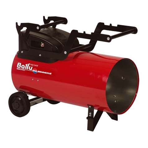
Ballu BOGH-15 User manual

BOGH-15 BOGH-15E
Operation manual
Gas infrared heater
Before operating
study this manual and keep it accessible
Code-128
1837
18

2
2 Used notation
3 Safety regulations
5 General description
6 Safety instruction
7 Appliance design
12 Specifications
13 Preparation for work
16 Control
19 Maintenance
20 Troubleshooting
21 Transportation and storage
21 Scope of supply
21 Electrical schematic diagram
22 Lifetime
22 Warranty
22 Disposal rules
22 Date of manufacture
22 Product certification
1. Used notation
Contents
ATTENTION!
Requirements which, if ignored, may result in serious
injury or serious equipment damage.
CAUTION!
Requirements which, if ignored, may result in serious injury or
death.
NOTE:
1. In the text of this manual, the infrared gas heater may
have such technical names as the device, appliance,
apparatus.
2. If the gas hose or gearbox is damaged, it must be replaced
by the manufacturer or an authorized service center to
avoid serious injury.
3. The device must be installed in compliance with existing
local regulations and regulations for the use of gaseous
fuel devices.
4. The manufacturer reserves the right to without prior notice
to the buyer to make changes in the design, equipment
or technology of the product in order to improve its
properties.
5. The text and numerical designations of the instructions may
be misprints.
6. If, after reading the instructions, you still have questions
about the operation of the device, contact the seller or a
specialized service center for clarification.
7. On the product there is a label on which the technical
characteristics and other useful information about the
device are indicated.

3
2. Safety regulations
ATTENTION!
• When operating an infrared
gas heater, follow general
safety rules when using gas
equipment.
• The infrared gas heater must
be protected from shocks, dust
and moisture.
• The use of an infrared gas
heater in rooms is prohibited:
with a relative humidity of more
than 98%, with an explosive
atmosphere; with biological
environment; highly dusty
environment; with a corrosive
environment for materials.
• Long-term operation of an
infrared gas heater without
supervision is prohibited.
• Before starting cleaning or
maintenance, or during a long
interruption in operation, turn
off the instrument, shut off the
gas supply and disconnect the
gas cylinder.
• Never move a working device.
• Shut off the gas supply to the
gas cylinder before moving
device.
• Do not cover the unit and do
not restrict the flow of air.
Before turning on the infrared
gas heater, remove foreign
objects around it. All flammable
substances must be removed
from the room. Minimum
distances in front of an infrared
gas heater: - in fig. 1c
• To avoid burns, do not touch
the outer surface, as well as the
upper part of the case, while the
infrared gas heater is in heating
mode.
• To avoid injury, do not remove
the protective grille from the
housing.
• Do not use the device for other
than its intended purpose
(drying clothes, etc.).
• Do not attempt to repair the
device yourself. Contact a
qualified technician.
• Replace the gas hose once a
year.
• Use only the type of gas and
gas cylinder specified in these
instructions.
• With strong wind, the product

4
may be tilted. Pay special
attention to tilting the instrument.
• This product can be used
outdoors or in a well-ventilated
area.
A well ventilated area should
have a minimum of 25% open
surface area. The surface area
is calculated as the sum of
the areas of all surfaces of the
walls.
• After transportation at negative
temperatures, it is necessary to
keep the infrared gas heater in
the room where it is supposed
to be used for at least 2 hours.
• The device is not intended to
be used by persons (including
children) with reduced physical
or mental abilities or in the
absence of life experience or
knowledge if they are not under
control or instructed to use the
device by a person responsible
for their safety.
• Children should be supervised
to prevent play with the device.
• Modification of the device is
strictly prohibited, except as
specified and approved by the
manufacturer.
• For safety reasons for children,
do not leave packaging (plastic
wrap, cardboard) unattended.
• Do not allow children to play
with plastic wrap. Choking
hazard!
CAUTION!
• Never use an infrared gas heater
indoors, or near inflammable
objects, flammable liquids.
Danger of fire!
• During operation, check that the
room is adequately ventilated.
Use only in well ventilated
areas. Insufficient ventilation
can lead to carbon monoxide
poisoning, smoke, and fires.
• This heater is a fire heater that is
not connected to the chimney.
While the heater is running,
make sure that the room is well
ventilated. Do not use the unit
in a bedroom, van, boat or any
other room with a capacity of
less than 80 cubic meters.
• In the event of a gas leak, do not
use the device. If the product
works, immediately shut off
the gas supply. Before reuse,

5
heating
radius
850
609,5 min. 4 m
2339,5
1486,5
min. 0.5 m
check the device and repair the
leak with a qualified technician.
• Do not install a working heater
close to walls, curtains or
furniture. The heater must
always be turned towards the
center of the room. Adjust
the position of the heater as
described below:
Fig. 1a - Proper placement of the device in an
open well-ventilated area
Fig.1b - Incorrect placement of the device in a
closed poorly ventilated room
Fig. 1c - Device dimensions and tolerances
(0.5 min)
3. General description
Purpose
• Outdoor gas infrared heater has the shape of a
trihedral pyramid, the base is made of a metal
frame on which decorative panels are mounted.
At the base of the device provides a place for
concealed installation of a gas cylinder up to
27 liters. On top of the base, there are guides,
to which the protective grille, the afterburner
and the deflector are fixed. A glass flask made
of special glass is installed in special holes (at
the base and in the afterburner). The visor is
attached to the afterburner.
• Due to the features of the heater, it allows you
to heat an area of up to 20 square meters in
rooms with good air ventilation, for example:
terraces, gazebos, restaurants, cafes, outdoor
areas. The device is equipped with an ignition
system with an ODS sensor that reacts to the
presence of sufficient oxygen for burning;
in the event of a lack of oxygen, the device
automatically switches off. Also, the device is
equipped with a sensor that reacts to the tilt of
the device - in case of a falling device, the gas
automatically shuts off.
• The BOGH-15E model can be controlled using
either an electronic control unit or a remote
control panel. Installed remote receiver signals
from the remote control. The range of the
control panel is up to 3 meters.
ATTENTION!
If the safety instructions and
operating instructions for this
equipment are not followed,
the manufacturer declines
responsibility for accidents and
damage caused to people, as
well as damage to equipment.

6
4. Safety Instructions
• Carefully read the instructions
before use. Familiarize yourself
with the device and methods
of controlling an infrared gas
heater.
• Follow the maintenance
instructions and fault table
described in this manual.
• Do not block the inlet and outlet
of the infrared gas heater.
• Do not block the ventilation
openings of the compartment
where the gas cylinder is located.
• Do not use infrared gas heaters
in basements and other areas
below ground level.
• In the room where the infrared
gas heater works, there must
be constant ventilation in
accordance with the technical
specifications.
• The size of the room should
not be less than specified in the
technical specifications.
• The infrared gas heater should
not be used in the immediate
vicinity of explosive substances.
• Do not heat gas cylinders, even
if the cylinder is “frozen”.
• Installation, transportation and
storage of gas cylinders should
be carried out in accordance
with the rules, regulations and
instructions for safe operation
adopted in your area.
• The product must be repaired
only by a qualified, authorized
service center worker.
• To ensure safety, always turn
off the gas cylinder before
disassembling an infrared gas
heater, for maintenance, or when
the heater is not in use.
• When installing infrared gas
heaters, follow the rules and
regulations for the installation
of similar equipment adopted in
your area.
• Replace gas cylinders in a
room with sufficient ventilation
away from the source of ignition
(candles, cigarettes and other
sources of ignition and flammable
substances).
• Use only special gas cylinders.
It is advisable to use only propane
gas.
• Sometimes a balloon may be
covered with frost - “freeze”. This
situation usually occurs when
there is not enough gas in the
cylinder. To reduce the likelihood
of the gas cylinder freezing effect,
it is recommended to work with
the minimum required gas flow
rate. There is a tacit rule that for
every kW should be 1 liter of gas,
therefore, 13 kW need 13 liters of
liquefied gas. For this equipment,
you must purchase a suitable
gas cylinder (27 l.).

7
• Never move the unit with a lit
flame.
• When replacing a cylinder,
check with soapy water or
equivalent to see if there is a gas
leak from the reducer or from the
cylinder.
• Ensure that the gas reducer is
installed correctly, securely, and
there is a rubber gasket on it.
5. Appliance design
5.1 Model BOGH-15
14
6
5
7
8
12
11
10
9
2
3
13
Fig. 2 – BOGH-15 model design
1. Glass flask in individual packaging;
2. The middle base of the gas heater assembly
with the control unit;
3. The lower base of the gas heater;
4. Visor;
5. The afterburner;
6. Visor stand;
7. Removable side cover;
8. Non-removable side cover (2 pcs.);
9. Upper profile (3 pcs.);
10. Protective grille (3 pcs.);
11. The top bar for the grille (3 pcs.);
12. Chain in lavsan winding with two carbines
for fixing the gas cylinder;
13. Metal stoppers.

8
Burner design
Battery replacement:
AA battery is used for electrical ignition. To
replace the battery, unscrew the ignition cap
counterclockwise. Remove the old battery and
insert a new one.
IMPORTANT!
• When installing batteries,
observe the polarity (+/–
contacts). Otherwise, batteries
may leak, explode or ignite.
• If the device is not used for a
long time, remove the batteries.
Otherwise, the batteries may fail
(leak or run out).
• If the battery leaks, before
inserting a new one, dry the
battery compartment dry. If
combustion chamber
nozzle
burner tube
tipping sensor
ODS sensor
AA battery
electrical ignition
adjustment knob
choke
control valve
valve connection tube
with ODS sensor
Fig. 3 - Design of the control unit for the model BOGH-15

9
spilled electrolyte gets into your
eyes, rinse them thoroughly with
running water. Do not rub your
eyes. Contact with electrolyte
on clothing or skin is fraught with
burns. If this happens, flush the
electrolyte with water and seek
medical help.
• Used batteries are to be
disposed of.
• When disposing of used
batteries, follow the instructions
indicated on their case and
adhere to the regulations
established in your country.
Fig.4 - Replacing batteries for model BOGH-15
electrical ignition cover
1
7
8
12
11
10
9
2
3
13
4
6
5
5.2 Model BOGH-15Е
Fig. 5 - Design model BOGH-15E
1. Glass flask in individual packaging;
2. Medium base gas lamp assembly with a
control unit;
3. The lower base of the gas lamp;
4. Visor;
5. The afterburner;
6. Visor stand;
7. Removable side cover;
8. Non-removable side cover (2 pcs.);
9. Top profile (3 pcs.);
10. Protective grille (3 pcs.);
11. The top bar for the grille (3 pcs.);
12. Chain in the lavsan winding with two
karabinas for fixing the gas cylinder;
13. Metal stoppers.

10
combustion chamber
nozzle
burner tube
tting tube-burner
electronic control unit
D battery
choke
battery box
tipping sensor
ODS sensor
Burner design
Battery replacement
For operation of the device, batteries of type D are
used in the amount of 2 pcs. To replace the batteries,
open the battery cover, remove the old batteries and
install new ones.
The remote control uses AAA batteries in the amount
of 2 pcs. To replace the batteries, open the back
cover of the control panel, remove the old batteries
and install new ones.
Fig. 6 - Design of the control unit for the model BOGH-15E
IMPORTANT!
• When installing batteries,
observe the polarity (+/–
contacts). Otherwise, batteries
may leak, explode or ignite.
• When installing and replacing
batteries, turn off power to the
device.
• If the device is not used for a

11
long time, remove the batteries.
Otherwise, the batteries may
fail (leak or run out).
• If the battery leaks, before
inserting a new one, dry the
battery compartment dry. If
spilled electrolyte gets into your
eyes, rinse them thoroughly with
running water. Do not rub your
eyes. Contact with electrolyte
on clothing or skin is fraught
with burns. If this happens,
flush the electrolyte with water
and seek medical help.
• Used batteries are to be
disposed of.
• When disposing of used
batteries, follow the instructions
indicated on their case and
adhere to the regulations
established in your country.
Fig.7 - Replacing batteries for model BOGH-15E
battery cover
Remote
signal
receiver
Remote signal receiver
The device is equipped with a sensor that receives
commands from a remote control panel.
Fig.8 - Sensor position for model BOGH-15Е
IMPORTANT!
• For correct and reliable
operation, do not allow the
sensor to become dirty, do not
block or block the sensor with
foreign objects.

12
Name of parameter BOGH-15 BOGH-15E
Rated power, kW 13.0 13.0
Gas pressure in the reducer, mbar 37.0 37.0
Gas Consumption (min-max), kg/h 0.3-0.97 0.3-0.97
Fuel type Propane, propane/
butane
Propane, propane/
butane
Category products I3B/P
Country of destination
AT, BE, BG, CH, CY, CZ, DE, DK, EE, ES, FI, FR,
GB, GR, HU, IE, IS, IT, LV, LT, LU, NL, NO, PT, SE,
SI, SK, TR
Type of gas G30/37
Hose type
Sleeve I-18 -0.63
( I- propane and butane for filing under a maximum
pressure of 0.63 Mpa;
18-nominal outer diameter (mm)
9-nominal internal diameter (mm)). Length 50 cm.
Ignition method Electrical ignition Automatic
electrical ignition
Volume of the recommended gas cylinder, l up to 27.0 up to 27.0
Heating radius, m 2-2.5 2-2.5
Heating area, m2up to 20 up to 20
Way to move Built-in wheelbase Built-in wheelbase
Battery operation АА-type battery - 1 pc. D-type battery (LR20)
2 pc.
Battery Remote Control - ААА-type battery 2 pc.
Operating current, mA -100
Electrical protection class 3 class 3 class
Operating temperature, С° (up -20 to +30) (up -20 to +30)
Degree of protection, IP
IP44 IP44
Dimensions of the appliance (WxHxD), mm 847х2410х770 847х2410х770
Package dimensions (WxHxD), mm 1450х560х560 1450х560х560
Net weight, kg 40 40
Gross weight, kg 45 45
6. Specifications

13
the profile on this screw and tighten the screw 2, then
tighten the screw 1;
Fig.10 - Installing the top profiles
• Attach the screws to the afterburner for installation
in the slots of the upper profiles (Fig. 11)
IMPORTANT!
Assembled afterburner with pre-
tightened M4 screws, made of
stainless steel in a quantity of
12 pcs. It is not recommended
to use galvanized screws, since
These screws are not designed for
operation at elevated temperatures.
7. Preparation for work
To build the device, you will need a screwdriver
with a cross (or Phillips) slot;
The assembled afterburner comes 1 assembled
with visor racks. For convenience 2
Assembly disconnect the visor from the
afterburner.
IMPORTANT!
Always use personal protective
equipment - cotton gloves during
assembly and heater installation.
For convenience and safety, the heater should be
assembled by two people.
• Before assembly, remove the protective film
from the parts of the product;
• All necessary screws are pre-tightened into the
seats;
• Before assembly, lock the two wheels of the
instrument by lowering the metal stop down -
This will ensure the stability of the device from
unwanted movements.
Fig.9 - Installing the stoppers
• Install the profiles on the bottom of the pre-
assembled part of the gas heater (Fig. 10). To do this,
make a screw in the middle base, which corresponds
to a slot in the profile (near the center hole). Install
Metal
stoppers
А
medium base
top prole
1
2
А
А
medium base
top prole
1
2
А
Metal
stoppers

14
Fig.11 - Installation of screws on the afterburner
• Remove the flask from the box and carefully insert
the flask, and install the afterburner onto the profiles
(fig.12) from the top, fixing the flask, tighten the
screws;
Fig.12 - Installing the flask and the afterburner
• Install the grilles into the grooves of the upper
profiles (Fig. 13);
Fig.13 - Grille installation
• • For reliable fixation of the grille, one of the
mounting options is possible (a or b):
a) Secure the grille with a strap (Figure 14a);
Fig.14a - Grille fastening
b) Install the grille retainer into the groove in the
upper profile (Figure 14b):
Fig.14b - Install grille lock
• Connect the elements of the visor together, as
shown in Fig. 15. Fasten the connections with
А
grooves for
mounting
the grilles
А
grille strip
A A
Screw М4
afterburner
ask
groove in the
top prole for
the installation
of the afterburner
А
А
А
afterburner
ask
А
groove in the
top prole for
the installation
of the afterburner

15
M4x8 stainless steel screws. Attach the visor
cover with the M4x8 screws to the assembled
visor.
Fig.15 - Assembling the visor
• Install a visor on the afterburner, fasten the visor
on stainless steel M6 butterfly nuts (Fig. 16);
Fig.16 - Installing the visor
• Install side covers, fasten them to countersunk
head screws;
• Install the main cover, using magnets on the base
of the device;
Fig.17 - Main and side covers
• Lift the wheel stopper up and move the device
to its destination. Congratulations, you have
completed the build!
buttery nut M6
Gas connections
• Connect the gas pressure regulator (regulator)
to the cylinder. The thread on the cylinder and the
gearbox is left.
• Tighten the adjuster nut with the wrench to 27.
• Install the cylinder as shown in the pictures 2
and 5.
To assemble the table, you must perform the
following steps:
1. remove the side and main covers from the
product;
2. unscrew the screws (4) securing the upper
profile (1);
3. Get the corner (2) in the slot of the support (3);
4. Insert screws into the holes and tighten them;
5. repeat steps 2-4 for the remaining supports
(Fig. 18);
6. install the stand as shown in Fig. 19, put the
bolts into the holes, but do not tighten them
with nuts;
7. Holding the first stand, install the second stand
as shown in Fig. 20, bolt the holes. Put nuts on
the bolts, but do not tighten them until the end
of the assembly;
main cover
side cover
screw holes
Visor cover
Visor element
Screw M4x8
3
2
1
4
Fig. 18
Fig. 19

16
8. Repeat step 7 to secure the last stand. You
should get the following (Fig. 21);
9. Tighten all bolts with a wrench;
10. Reinstall the side and main covers. Tighten the
screws that secure the side covers. Assembly
is complete (Fig. 22).
8. Control
IMPORTANT!
• Before the first start-up of the
device, it is necessary to release
a part of the gas-air mixture from
the gas cylinder by opening the
valve for 5-10 seconds. Perform
strictly in a well-ventilated area!
The air contained in the cylinder
forms a mixture with gas vapors,
which, when entering the burner,
will be unstable. For correct
operation of the instrument, after
filling the cylinder, it is necessary
Fig. 21
Fig. 20
Fig. 22

17
to carry out the procedure for
removing residual air from the
gas cylinder.
• Do not turn on the device
without a reflector cover or when
disassembled.
• The burner and glass tube must
never be completely or partially
covered.
• Do not turn on the device if the
glass bulb is damaged.
• Protect the device from impacts.
• Always place the device on a
sufficiently flat surface (angle of
inclination up to 10 °) to prevent
it from tilting.
• Do not place the unit on an
easily flammable surface (wood,
linoleum, synthetic floors, etc.).
• The heater is equipped with
a safety device that cuts off the
gas supply in case of inclination
by more than 45 °.
• When first turned on, the device
may emit smoke and odor for a
short time.
• After installing the cylinder,
the wick is ignited after a while
(usually 1-2 minutes). This is due
to the fact that there is air in the
gas path and it takes some time
to remove it from the gas path.
• Use of the heater at temperatures
below 0°C
• When using a heater in frosty or humid weather, it is
necessary to turn on the flame to the minimum mode, to
warm the glass, after the condensate disappears inside
the flask, gradually increase the height of the flame
column.
• When the gas temperature drops below 0 ° C, the
pressure in the cylinder decreases, and as a result, the
height of the flame column may decrease.
IMPORTANT!
• When the air temperature is
below + 10 ° C, use high-quality
gas, preferably pure propane,
otherwise the flame height may
decrease.
Startup sequence for Ballu BOGH-15
model:
• Ensure that the device is fully assembled;
• Turn the device in the opposite direction from the wind
to avoid blowing out the flame;
• Open the main cover;
• Open the valve on the gas cylinder;
• Press and turn the control knob to the START position.
• Simultaneously press the ignition button until the
ignition flame appears (behind the glass on the side of
the ceramic panel).
• Continue to hold the control knob in the depressed
position for 10-15 seconds after ignition. If the flame goes
out when the knob is released, repeat the previous two
points.
• Turn the control knob to MIN.
• Press the handle and gently turn counterclockwise.
Adjust the height of the flame.
• Close the main cover.
• Enjoy working appliance.

18
Fig.23 - Control panel panel for model BOGH-15
Startup sequence for Ballu BOGH-15E
model:
• Ensure that the heater is fully assembled;
• Turn the device in the opposite direction from the wind
to avoid blowing out the flame;
• Open the main cover;
• Open the valve on the gas cylinder;
• Press the "Power" button on the electronic control
panel of the unit, at the same time a beep will sound on
the panel and the red LED will automatically process
the ignition gas heater starts. The device will turn on for
maximum operation;
• If the flame does not appear, repeat the previous step
as long as the heater automatically turns on;
• To start the gas heater via the control unit to press
and hold the "Power" on the remote control and wait
twice the audio signal on the control panel, the green
LED lights up. Once again press the "Power" button on
the remote control, an alarm will sound and the ignition
process of the gas heater starts. The device will turn on
for maximum operation;
• If the flame does not appear, repeat the previous step
as long as the heater will not start;
• After starting the heater, adjust the flame height using
the buttons "Up" and "Down" on the remote control.
• Close the main cover.
• Enjoy working appliance.
Инструкция
1. О ткройте вентиль на установленном газовом баллоне.
2. Н ажмите и поверните ручку управления в положение START.
3. О дновременно нажмите кнопку зажигания до появления
пламени запала (за стеклом сбоку от керамической панели).
4. П родолжайте удерживать ручку управления в нажатом
положении 10-15 секунд послезажигания. Если при отпускании
ручки гаснет пламя запала, повторите п.п.2-3.
5. П оверните ручку управления в положение min. Плавно
нажмите на регулировочную ручку и одновременно поворачивайте
против часовой стрелки. Отрегулируйте высоту пламени.
6. Для отключения обогревателя переведите ручку управления
в положение OFF и закройте вентиль на установленном
газовом баллоне.
max
min
START
OFF
www.ballu.ru
Сделано в России
IMPORTANT!
• When first switched on, the
ignition flame may not appear for
some time.
The shutdown sequence for the Ballu
BOGH-15 model:
• Open the main cover;
• To disconnect, turn the left knob to the “OFF”
position.
• Close the valve on the gas cylinder;
• Close the main cover.
The shutdown sequence for the Ballu
BOGH-15E model:
• Open the main cover;
• To disconnect, press the "Power" button on the
electronic control panel several times depending on
the selected power mode. The order of switching
off the device, if the device was at the maximum
operating mode
- press the “Power” button once - the device will
switch to the average power mode;
- press the “Power” button once - the device will
switch to the minimum power mode;
- press the “Power” button once - the device will
switch to the fuse mode;
- press the “Power” button once - the device will turn
off.
• To turn off the instrument using the remote control,
press the “Power” button on the remote control.
• Close the valve on the gas cylinder;
• Close the main cover;
Moving the appliance:
• Move only the disconnected device;
• The device is equipped with wheels for movement,
2 rear wheels (fixed) with stops, one front wheel freely
rotating 360 degrees;
• To move, remove the device from the stoppers that
are located on the side of the main cover;
• After moving, be sure to place the instrument on
the stoppers.

19
9. Maintenance
IMPORTANT!
• Before performing any
maintenance operations, make
sure that the gas supply valve is
closed.
• To clean the inside of the glass
tube, use a dry soft cloth.
• Use of cleaning products can
also cause smudges and stains
that will be difficult to remove.
• Periodically check the integrity
of the gearbox and hose (once a
week and every time you replace
the gas cylinder. If cracks, chips
or other damage are found,
replace the hose with a new one
of the same length and the same
type). For replacement, use only
spare parts made at the heater
factory.
• Periodically check the visor of
the gas infrared lamp for soot
and soot. Clean the visor at least
1 time per week.
IMPORTANT!
• For safety reasons, the gas
cylinder can be refilled by no
more than 85%. That is, a 12-liter
gas cylinder cannot be refilled
for more than 11 liters. and in
a cylinder of 27 liters. not more
than 23 liters.
IMPORTANT!
• It is recommended to store
refilled cylinders at a temperature
of not less than + 5 ° С and not
more than + 20 ° С.
Pressure regulator
Before using the heater for the first time, it is
necessary to check the degree of tightening of
the hose clamps, and tighten if necessary.
Damage to the glass flask
• The technical features of the flask are designed
to resist thermal shock caused by normal
temperature fluctuations, rain or humidity.
• Despite the choice of this material (Borosilicate
or Quartz), flask damage may occur as a result
of special weather conditions and / or excessive
temperature fluctuations.
IMPORTANT!
Damage to the flask (crack) is not
dangerous to people or objects
in the immediate vicinity of the
heater.
IMPORTANT!
Damage to the flask does not
interfere with the operation of the
heater in the short term, but the
flask should be replaced to ensure
the normal operation of the heater.

20
Glitch The reason The decision
No flame
The shortage of gas supply (bad Gazi
classification of liquefied gas or dirt in the
system)/pressure regulator setting Len
wrong or defective
Adjust or replace empty cylinder/replace
gas
A sudden gust of wind (above 3 m/s) in
the absence of gas panels Remove heater from direct gusts of wind
Faulty thermocouple sensor'S SLM Replace
Defective solenoid valve Replace
Broken fuse or slope of the floor more
than 15 degrees
Replace the fuse or move-a on a surface
with a slope of less than 15 degrees
The obstruction in the gas system Check out and gently
Gas leak Check and fix leak
Isolation of electrodes or cable defect
pezopodzhiga Replace
"airbag" gas cylinder
Turn the gas cylinder to the gas from-
covered area away from ignition sources
within 10-15 seconds
Soot in a glass flask
Poor quality gas or gas of non-suitable
for winter
Use high-quality gas, one-person chtitelno
pure propane
Poor ventilation Remove the side covers, ventilate the
device, mount the side covers
Mixing chamber of gas mixture for-
grjaznena or damaged Clean/replace
The burner is dirty/damaged Clean/replace
Breakage of the glass
flask
Thermal shock due to weather conditions Replace flask
Unsuitable cleaning tools Replace flask
Accidental drop of the heater Replace flask
Does not light the wick
Clogged nozzles Wick You must purge the injectors Wick
Defective electronic control unit Replace
The appliance does not
respond to commands
from the remote control
Defective remote control Replace the batteries or replace remote
control
Defective remote receiver Replace
10. Troubleshooting.
Replacing / cleaning flasks:
If the flask is replaced or if it is necessary to clean
it, disassemble the instrument in the reverse order
(see the “Preparation” section), remove the flask (use
personal protective equipment when disassembling)
and clean it.
This manual suits for next models
1
Table of contents
Other Ballu Heater manuals
Popular Heater manuals by other brands

Sealey
Sealey CH30110V quick start guide

Kambrook
Kambrook KCE95 Instruction booklet

Dimplex
Dimplex RFI815D31 Installation, operation & maintenance instructions

Cadet
Cadet CEH-003M owner's guide

2VV
2VV ESSENSSE NEO VCES2-B...E3 Series installation manual

Kampmann
Kampmann Venkon EC installation instructions

Pinnacle Climate
Pinnacle Climate MH-150T-DFV-A User's manual and operating instructions

Frico
Frico CIR105 quick start guide

Bimar
Bimar S580.CH Instruction booklet

Soleus Air
Soleus Air HR3-08-21 operating instructions

Myson
Myson LO-LINE RC 6-4 Installation, operating, maintenance and after sales manual

Atlantic
Atlantic SOKIO user manual