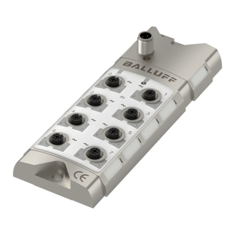
Balluff PROFINET BNI PNT-508-055-P067 User manual

BNI PNT-508-055-P067
deutsch Montageanleitung
english Installation guide
français Notice de montage
italiano Istruzioni di montaggio
polski Instrukcja montażu

1deutsch
BNI PNT-508-055-P067
Netzwerkschnittstelle
Zu dieser Anleitung
Diese Anleitung stellt wichtige Informationen bereit für den
Einbau und Anschluss des folgenden Profinet-IO-Link-
Masters:
– BNI PNT-508-055-P067
Bestellcode: BNI00EK
Mitgeltende Dokumente
Eine ausführliche Betriebsanleitung und weitere Informatio-
nen zu diesem Produkt finden Sie unter www.balluff.com
auf der Produktseite.
Bestimmungsgemäße Verwendung
Der Profinet-IO-Link-Master dient als ausgelagertes E/A-
und IO-Link-Modul zum Anschluss an ein PROFINET-Feld-
bus und ist für den Einsatz im Industriebereich vorgesehen.
Die einwandfreie Funktion gemäß den Angaben in den
technischen Daten wird nur mit geeignetem original Balluff
Zubehör zugesichert, die Verwendung anderer Komponen-
ten bewirkt Haftungsausschluss.
Eine nichtbestimmungsgemäße Verwendung ist nicht
zulässig und führt zum Verlust von Gewährleistungs- und
Haftungsansprüchen gegenüber dem Hersteller.
Vernünftigerweise vorhersehbare Fehlanwendung
Das Produkt ist für folgende Anwendungen und Bereiche
nicht bestimmt und darf dort nicht eingesetzt werden:
– in sicherheitsgerichteten Anwendungen, in denen die
Personensicherheit von der Gerätefunktion abhängt
– in explosionsgefährdeten Bereichen
Sicherheitshinweise
Tätigkeiten wie Einbau, Anschluss und Inbetriebnahme
dürfen nur durch geschulte Fachkräfte erfolgen.
Eine geschulte Fachkraft ist, wer aufgrund seiner fachli-
chen Ausbildung, seiner Kenntnisse und Erfahrungen
sowie seiner Kenntnisse der einschlägigen Bestimmungen
die ihm übertragenen Arbeiten beurteilen, mögliche Gefah-
ren erkennen und geeignete Sicherheitsmaßnahmen treffen
kann.
Der Betreiber hat die Verantwortung, dass die örtlich
geltenden Sicherheitsvorschriften eingehalten werden.
Insbesondere muss der Betreiber Maßnahmen treffen,
dass bei einem Defekt des Prokukts keine Gefahren für
Personen und Sachen entstehen können.
Das Produkt darf nicht geöffnet, umgebaut oder verändert
werden. Bei Defekten und nichtbehebbaren Störungen des
Produkts ist dieses außer Betrieb zu nehmen und gegen
unbefugte Benutzung zu sichern.
Die BNI-Module haben grundsätzlich eine gute Chemika-
lien- und Ölbeständigkeit. Beim Einsatz in aggressiven
Medien (z.B. Chemikalien, Öle, Schmier- und Kühlstoffe)
jeweils in hoher Konzentration (etwa durch geringen Was-
sergehalt) ist die Materialbeständigkeit vorab applikations-
bezogen zu überprüfen. Im Falle eines Ausfalls oder einer
Beschädigung der BNI-Module, bedingt durch solch
aggressive Medien, bestehen keine Mängelansprüche.
Heiße Oberflächen
Das Gehäuse erwärmt sich unter normalen Betriebsbedin-
gungen. Es besteht die Gefahr von Brandverletzungen.
Direkten Hautkontakt mit der Oberfläche vermeiden.
Abmessungen
00
00
00 00
IN
100 100
00
01
00 01
01 01
00
01 00 01
01 01
X00
XD1
BNI00EK
BNI PNT - 508 - 055 - P067
X01
X03
X05
X06 X07
MAC-ID
00-19-31-XX-XX-XX
M12x1 (8x) M12x1 (3x)
M12x1 (male)
226
208.5
8.5
7
65
68
1.8
31.5
0.5
26.3
36.8
26.3
Ø 7
00
00
00 00
IN
100 100
00
01
00 01
01 01
00
01 00 01
01 01
X00
XD1
BNI00EK
BNI PNT - 508 - 055 - P067
X01
X03
X05
X06 X07
MAC-ID
00-19-31-XX-XX-XX
M12x1 (8x) M12x1 (3x)
M12x1 (male)
226
208.5
8.5
7
65
68
1.8
31.5
0.5
26.3
36.8
26.3
Ø 7
Mit dem CE-Zeichen bestätigen wir,
dassunsere Produkte den Anforderungen
deraktuellen EU-Richtlinie entsprechen.
File E319845
Einstufung Type 1
Umgebungstemperatur +50°C

www.balluff.com 2deutsch
BNI PNT-508-055-P067
Netzwerkschnittstelle
Aufbau und Funktion
PROFINET Port 2PROFINET Port 1
Stromversorgung
Ausgang
Stromversorgung
Eingang
Port 1Port 0
Port 3Port 2
Port 5Port 4
Port 7Port 6
Befestigungsloch
Befestigungsloch
FE-Anschluss
Der Profinet-IO-Link-Master ist ein dezentrales und konfi-
gurierbares Gateway, das die Eingangs- und Ausgangssig-
nale von Standardsensoren und -aktoren sowie Prozess-
daten von angeschlossenen IO-Link-Geräten verarbeitet
und auswertet.
Die Daten werden über eine vorhandene Feldbus-Schnitt-
stelle an eine, vom Benutzer eingerichtete, übergeordnete
Steuerung zur Weiterverarbeitung übertragen.
Zur Konfiguration und Diagnose steht auf dem IO-Link-
Master ein Webserver zur Verfügung.
Anzeigeelemente
Port/Pin-LEDs
– LED00 – Port-Pin4
– LED01 – Port-Pin2
Port/Pin-LEDs Standard-Port
Anzeige Bedeutung
Aus Zustand der Eingangs- oder Ausgangs-
pins ist 0
Gelb Zustand der Eingangs- oder Ausgangs-
pins ist 1
Beide LEDs
rot blinkend
Kurzschluss der Sensorversorgung
zwischen Pin1 und Pin3
Rot Kurzschluss am Ausgang an Pin2/4
gegen Pin3
Rot Kein High-Signal am Diagnoseeingang
Rot 24-V-Eingangssignal auf konfiguriertem
Ausgang (Aktorwarnung)
Anzeigeelemente (Fortsetzung)
Port/Pin-LEDs IO-Link-Port
Anzeige Bedeutung
Grün IO-Link-Verbindung aktiv
Grün blin-
kend
Keine IO-Link-Verbindung oder falsches
IO-Link-Device
Grün schnell
blinkend
IO-Link: Preoperate während der Daten-
haltung
Rot schnell
blinkend
Validierung fehlgeschlagen / falsche
Konfiguration der IO-Link-Datenlänge
Rot schnell
blinkend
Datenhaltung fehlgeschlagen / falsches
Device für Datenhaltung
Rot IO-Link: Kurzschluss Pin 4 gegen Pin 3
Status-LEDs
LED Anzeige Bedeutung
US Grün Eingangsspannung OK
Rot blinkend Eingangsspannung gering
(<18V)
UA Grün Ausgangsspannung OK
Rot blinkend Ausgangsspannung gering
(<18V)
Rot Keine Ausgangsspannung
vorhanden (<11V)
SF Aus Kein Fehler
Rot Watchdog-Timeout; Kanal-,
allgemeine oder erweiterte
Diagnose liegt vor; Systemfehler
Rot blinkend Dienst DCP-Signal über Bus
gestartet
BF Aus Kein Fehler
Rot Geringe Geschwindigkeit des
physischen Links; oder kein
physischer Link
Rot blinkend Kein Datenaustausch oder keine
Konfiguration
MS Grün Kein Fehler
Blau blinkend Ping-Kommando
Blau Limitüberschreitung interner
Zähler (z.B. Betriebsstunden)
Gelb blinkend Sensorversorgung unter 18V
Aktorversorgung unter 18V
Keine Sensorversorgung 0V
Keine Aktorversorgung 0V
Temperatur zu niedrig
Temperatur zu hoch
Überspannung
Rot Interner Fehler
100 Aus Übertragungsrate: 10Mbit/s
Gelb blinkend Übertragungsrate: 100Mbit/s
XF1/2 Grün Datentransfer

3deutsch
BNI PNT-508-055-P067
Netzwerkschnittstelle
Einbau
Das Modul mit 2 M6-Schrauben und einem Anzugsdreh-
moment von 3Nm unter Verwendung der Befestigungslö-
cher befestigen.
Elektrischer Anschluss
Spannungsversorgung
ACHTUNG
Ungewollte Spannungseinbrüche
Nicht getrennte Stromkreise der Spannungsversorgun-
gen für Sensor und Aktor können beim Schalten von
Aktoren zu ungewollten Spannungseinbrüchen der
Sensorversorgung führen.
►Spannungsversorgungen für Sensorik und Aktorik
getrennt absichern.
►Auf eine ausreichende Dimensionierung der Span-
nungsversorgung des Geräts achten, um Anlauf-
und Spitzenströme abzudecken und das Absiche-
rungskonzept entsprechend auszulegen.
Für UL: Kabel-Anforderungen und Anforderungen
an die Spannungsversorgung beachten (siehe
Kapitel UL-Anforderungen)!
– Stromversorgung von Sensor/Bus und Aktor
sofern möglich über eine getrennte Stromquelle
herstellen.
– Der IO-Link Master BNI PNT-508-055-P067 darf
beim Einsatz mit galvanisch getrennten Geräten
wie z.B. BNI PNT-538-_05-Z063 nicht mit der
gleichen Stromquelle versorgt werden.
– Die Gesamtstromstärke für die Sensor- und
Aktorversorgung darf jeweils 16A nicht über-
schreiten.
M12-Stecker
(L-codiert)
M12-Buchse
(L-codiert)
(Draufsicht auf
M12-Stecker
und -Buchse)
Pin Signal Beschreibung
1 US Modul-/Sensorversorgung +24V
2GND Gemeinsame Masse
3
4 UA Aktorversorgung +24V
5 FE Funktionserde
Elektrischer Anschluss (Fortsetzung)
PROFINET-Schnittstelle
M12-Buchse, D-codiert (Draufsicht auf
Buchse)
Pin Signal Beschreibung
1 Tx+ Transmit Data +
2 Rx+ Receive Data +
3 Tx− Transmit Data −
4 Rx− Receive Data −
I/O-Port
M12-Buchse (Draufsicht auf Buchse)
Pin Signal Beschreibung
1 US +24V, 2A
2 I/O Eingang / Ausgang (1A / 2A / 4A)1)
3 GND Elektrische Masse 0V
4 I/O, C/Q Eingang / Ausgang (1A / 2A) /
IO-Link
5 n.c. Nicht verbunden
1) Einstellbar auf 1A, 2A und 4A unter Berücksichtigung des
Summenstroms von 16A und des maximalen Summenstroms von
4A auf dem GND-Pin des Ports
Für die digitalen Sensoreingänge, siehe Richtlinie
über Eingänge EN61131-2, Typ 3.
Ungenutzte Ports müssen mit Abdeckkappen
versehen werden, um die Schutzart IP68/IP69K zu
gewährleisten.

www.balluff.com 4deutsch
BNI PNT-508-055-P067
Netzwerkschnittstelle
Erdung
Um EMV-Störungen entge-
genzuwirken, muss der
Funktionserdungsanschluss
verwendet werden.
►Erdungsanschluss mit der
Funktionserde (FE) der
Maschine verbinden.
Der FE-Anschluss zwischen Gehäuse und Maschine
muss eine niedrige Impedanz aufweisen und so
kurz wie möglich sein.
►Erdungsband aus dem Lieferumfang
verwenden.
Thermisches Derating
Die Hochleistungsausgänge ermöglichen einen maximalen
Ausgangstrom mit bis zu 4Ampere an Pin2 (X00…X07)
mit thermischem Derating.
max. Ausgangstrom pro Pin in A
Umgebungstemperatur in °C
Kabelverlegung
Kabellänge
Die Ethernetleitung darf max. 100Meter lang sein.
Die IO-Link-Anschlussleitung darf max. 20Meter lang sein.
Elektrischer Anschluss (Fortsetzung)

5deutsch
BNI PNT-508-055-P067
Netzwerkschnittstelle
Spannungsversorgung
Die Spannungsversorgung muss ein isolierter Typ oder ein
SELV-Typ sein.
Reinigung
Das Produkt nur mit einem trockenen oder nur mit Wasser
angefeuchteten Tuch reinigen!
Leistungsdaten
Spannungseingang,
Nennbereich 24VDC
– 130mA maximaler Verbrauch
– 16A einschließlich aller Aus-
gangslasten
Spannungsausgang,
Nennbereich 24VDC
– max. 16A
Digitaleingang, Nenn-
bereich 24VDC
– max. 30mA/Pin
Digitalausgang, Nenn-
bereich 24VDC
ClassA IO-Link-Port
– 0,5 A/Port Pilot Duty
– 4 A/Port Widerstandsbetrieb/
allgemeiner Gebrauch
– 16 A oder weniger pro Gerät
Kabelgrößen
Stromversorgungskabel:
Gelistetes oder R/C-Kabel (CYJV2/8) mit M12-Innenge-
winde und L-codiertem Stecker mit mindestens 24V,
mindestens 16A für alle Modelle. Mit S, SJ, SO, ST, SV
oder R/C (AVLV2) gelistete Kabel, die auf der UL Style
Page als für externe Verbindungen geeignet gekennzeich-
net oder spezifiziert sind, mit einem Nennwert von mindes-
tens 300V, mindestens 14AWG, es sei denn, sie sind mit
dem maximalen Laststrom und dem Überstromschutz für
das Kabel in Übereinstimmung mit der nachstehenden
Tabelle gekennzeichnet.
Netzanschlusskabel:
Gelistetes oder R/C-Kabel (CYJV2/8) mit einem M12
L-codierten Stecker mit Gewinde und einer Nennspannung
von mindestens 24V und mindestens 16A für alle
Modelle. Gelistetes S-, SJ-, SO-, ST-, SV- oder R/C-Kabel
(AVLV2), das auf der UL Style Page als für externe Verbin-
dungen geeignet gekennzeichnet oder spezifiziert ist, mit
einem Nennwert von mindestens 300V und mindestens
14AWG, es sei denn, es ist mit dem maximalen Laststrom
und dem Überstromschutz für das Kabel in Übereinstim-
mung mit der unten stehenden Tabelle gekennzeichnet.
Kommunikationskabel:
Gelistetes oder R/C-Kabel (CYJV2) mit A-, B- oder
D-codiertem Außen- oder Innengewinde, je nach Anwend-
barkeit zum Anschluss an Artikel9, M12-Stecker mit
mindestens 24V und mindestens 1A. R/C (AVLV2),
gekennzeichnet oder auf der UL Style Page als geeignet
für externe Verbindungen angegeben, Kabel mit mindes-
tens 28AWG und mindestens 300V.
Ein-/Ausgangskabel:
Gelistetes oder R/C-Kabel (CYJV2) mit A-codiertem
M12-Stecker mit Gewinde, mindestens 24V, mindestens
2A. R/C (AVLV2), gekennzeichnet oder auf der UL Style
Page als für externe Verbindungen geeignet angegeben
Kabel mit einem Nennwert von mindestens 300V, mindes-
tens 24AWG, es sei denn, der maximale Laststrom und
der Überstromschutz für das Kabel sind gemäß der nach-
stehenden Tabelle angegeben.
Größe des
Kabelleiters,
AWG
14 14 16 18 20 22 24 26 28 30
Überstrom-
schutz maxi-
male Ampere-
zahl [Ampere]
16 12 8 5,6 5 3 2 1 0,8 0,5
Maximale Last
[Ampere]
16 9 8 5,6 4 2,4 1,6 0,8 0,6 0,4
949458_AA ∙ DE ∙ J22; Änderungen vorbehalten. Ersetzt K21.
UL-Anforderungen
www.balluff.com 1english
BNI PNT-508-055-P067
Network interface
949458_AA ∙ DE ∙ J22; Änderungen vorbehalten. Ersetzt K21.
About this guide
This guide provides important information about the
installation and connection of the following Profinet-IO-Link
master:
– BNI PNT-508-055-P067
Order code: BNI00EK
Other applicable documents
A comprehensive user’s guide and additional information
about this product can be found at www.balluff.com on
the product page.
Intended use
The Profinet IO-Link master serves as decentralized I/O
and IO-Link Block for connection to a PROFINET fieldbus
and is intended for use in industrial applications.
Flawless function in accordance with the specifications in
the technical data is ensured only when using suitable
original Balluff accessories. Use of any other components
will void the warranty.
Non-approved use is not permitted and will result in the
loss of warranty and liability claims against the
manufacturer.
Reasonably foreseeable misuse
The product is not intended for the following applications
and areas and may not be used there:
– In safety-oriented applications in which personal safety
depends on the device function
– In explosive atmospheres
Safety notes
Activities such as installation, connection and
commissioning may only be carried out by qualified
personnel.
Qualified personnel are persons whose technical
training, knowledge and experience as well as knowledge
of the relevant regulations allow them to assess the work
assigned to them, recognize possible hazards and take
appropriate safety measures.
The operator is responsible for ensuring that local safety
regulations are observed.
In particular, the operator must take steps to ensure that a
defect in the product will not result in hazards to persons
or equipment.
The product must not be opened, modified or changed. If
defects and unresolvable faults occur in the product, take
it out of service and secure against unauthorized use.
The BNI modules generally have good chemical and oil
resistance. When used in aggressive media (e.g.
chemicals, oils, lubricants and coolants) in high
concentrations (e.g. due to low water content), the material
resistance must be checked in advance for the specific
application. In the event of failure or damage to the BNI
modules due to these kinds of aggressive media, claims
for defects are ruled out.
Hot surfaces
The housing heats up under normal operating conditions.
There is a risk of burn injuries. Avoid direct skin contact
with the surface.
Dimensions
00
00
00 00
IN
100 100
00
01
00 01
01 01
00
01 00 01
01 01
X00
XD1
BNI00EK
BNI PNT - 508 - 055 - P067
X01
X03
X05
X06 X07
MAC-ID
00-19-31-XX-XX-XX
M12x1 (8x) M12x1 (3x)
M12x1 (male)
226
208.5
8.5
7
65
68
1.8
31.5
0.5
26.3
36.8
26.3
Ø 7
00
00
00 00
IN
100 100
00
01
00 01
01 01
00
01 00 01
01 01
X00
XD1
BNI00EK
BNI PNT - 508 - 055 - P067
X01
X03
X05
X06 X07
MAC-ID
00-19-31-XX-XX-XX
M12x1 (8x) M12x1 (3x)
M12x1 (male)
226
208.5
8.5
7
65
68
1.8
31.5
0.5
26.3
36.8
26.3
Ø 7
The CE Mark verifies
that our products meetthe requirements
ofthecurrentEUDirective.
File E319845
Enclosure rating Type 1
Ambient temperature +50°C

2english
BNI PNT-508-055-P067
Network interface
Design and function
PROFINET Port 2PROFINET Port 1
Power supply
output
Power supply input
Port 1Port 0
Port 3Port 2
Port 5Port 4
Port 7Port 6
Mounting hole
Mounting hole
FE connection
The Profinet IO-Link master is a decentralized and
configurable gateway that processes and evaluates the
input and output signals of standard sensors and actuators
as well as process data from connected IO-Link devices.
The data is transmitted via an existing fieldbus interface to
a higher-level controller set up by the user for further
processing.
A web server is available on the IO-Link master for
configuration and diagnostics.
Display elements
Port/Pin LEDs
– LED00 – Port-Pin4
– LED01 – Port-Pin2
Port/Pin LEDs Standard-Port
Display Meaning
Off State of input or output pin is 0
Yellow State of input or output pin is 1
Both LEDs
flashing red
Short circuit of sensor supply between
pin1 and pin3
Red Short circuit at output on pin2/4 against
pin3
Red No high signal at diagnostic input
Red 24 V input signal on configured output
(actuator warning)
Display elements (continued)
Port/Pin LEDs IO-Link Port
Display Meaning
Green IO-Link connection active
Flashing
green
No IO-Link connection or incorrect
IO-Link device
Green, fast
flashing
IO-Link: Preoperate during data storage
Red, fast
flashing
Validation failed / incorrect configuration
of the IO-Link data length
Red, fast
flashing
Data storage failed / incorrect device for
data storage
Red IO-Link: Short circuit of pin 4 against
pin3
Status LEDs
LED Display Meaning
US Green Input voltage OK
Red flashing Input voltage low (<18V)
UA Green Output voltage OK
Red flashing Output voltage low (<18V)
Red No output voltage present
(<11V)
SF Off No error
Red Watchdog timeout; channel,
general or extended diagnostics
present; system error
Red flashing Service DCP signal started via
bus
BF Off No error
Red Low speed of physical link; or no
physical link
Red flashing No data exchange or no
configuration
MS Green No error
Blue flashing Ping command
Blue Limit exceeded by internal
counter (e.g. operating hours)
Yellow
flashing
Sensor supply below 18V
Actuator supply below 18V
No sensor supply 0V
No actuator supply 0V
Temperature too low
Temperature too high
Overvoltage
Red Internal failure
100 Off Transmission rate: 10Mbit/s
Yellow Transmission rate: 100Mbit/s
XF1/2 Green
flashing
Data transfer

www.balluff.com 3english
BNI PNT-508-055-P067
Network interface
Installation
Fasten the module with 2M6 screws and a tightening
torque of 3Nm using the mounting holes.
Electrical connection
Power supply
NOTICE
Unwanted voltage dips
Non-separated electric circuits of the power supplies for
sensor and actuator can lead to unwanted voltage dips
of the sensor supply when switching actuators.
►Fuse the power supplies for sensors and actuators
separately.
►Make sure that the power supply of the device is
sufficiently dimensioned to cover start-up and peak
currents and design the fuse protection concept
accordingly.
For UL: Observe cable requirements and power
supply requirements (see chapter
ULrequirements)!
– Establish power supply of sensor/bus and
actuator via a separate power source if possible.
– The IO-Link master BNI PNT-508-055-P067
must not be supplied with the same power
source when used with galvanically isolated
devices such as the BNI PNT-538-_05-Z063.
– The total current for the sensor and actuator
supply must not exceed 16A each.
M12 plug
(L-coded)
M12 socket
(L-coded)
(Top view of
M12 plug and
socket)
Pin Signal Description
1 US Module/sensor voltage +24V
2GND Common ground
3
4 UA Actuator supply +24V
5 FE Functional earth
Electrical connection (continued)
PROFINET interface
Top view of M12 socket, D-coded
Pin Signal Description
1 Tx+ Transmit Data +
2 Rx+ Receive Data +
3 Tx− Transmit Data −
4 Rx− Receive Data −
I/O Port
Top view of M12 socket
Pin Signal Description
1 US +24V, 2A
2 I/O Input / Output (1A / 2A / 4A)1)
3 GND Electrical ground 0V
4 I/O, C/Q Input / Output (1A / 2A) / IO-Link
5 n.c. Not connected
1) Configurable to 1A, 2A and 4A, taking into consideration the total
current of 16A and the max. total current of 4A on the GND pin of
the port
For the digital sensor inputs, see the directive on
inputs EN61131-2, type 3.
Unused ports must be covered with caps to
ensure IP68/IP69K protection.

4english
BNI PNT-508-055-P067
Network interface
Grounding
To counteract EMC
interference, the functional
earth connection must be
used.
►Connect the earth
terminal to the
functional earth (FE) of
the machine.
The FE connection between the housing and the
machine must have a low impedance and be as
short as possible.
►Use the grounding strap included in the scope
of delivery.
Thermal derating
The high power outputs allow a maximum output current
of up to 4amps at pin2 (X00…X07) with thermal derating.
Ambient temperature in °C
Max. output current per pin in A
Cable routing
Cable length
The Ethernet cable may be max. 100meters long.
The IO-Link single-ended cordset may be max. 20meters
long.
Electrical connection (continued)

www.balluff.com 5english
BNI PNT-508-055-P067
Network interface
Cord Sizes
Power In cord assembly:
Listed or R/C (CYJV2/8) cord assembly with threaded
female M12 L-coded connector rated 24 V minimum, 16 A
minimum for all models. Cord Listed S, SJ, SO, ST, SV, or
R/C (AVLV2) marked or specified in UL style page as
suitable for external interconnection rated 300 V minimum,
14 AWG minimum unless marked with maximum load
current and overcurrent protection for the cord in
accordance with table below.
Power Out cord assembly:
Listed or R/C (CYJV2/8) cord assembly with threaded male
M12 L-coded connector rated 24 V minimum, 16 A
minimum for all models. Cord Listed S, SJ, SO, ST, SV, or
R/C (AVLV2) marked or specified in UL style page as
suitable for external interconnection rated 300 V minimum,
14 AWG minimum unless marked with maximum load
current and overcurrent protection for the cord in
accordance with table below.
Communication cord assembly:
Listed or R/C (CYJV2) cord assembly with threaded male
or female A, B, or D-coded, as applicable to mate with
item 9, M12 connector rated 24 V minimum, 1 A minimum.
R/C (AVLV2) marked or specified in UL style page as
suitable for external interconnection 28 AWG minimum,
300 V minimum cord.
In/Out cord assembly:
Listed or R/C (CYJV2) cord assembly with threaded male
A-coded M12 connector rated 24 V minimum, 2 A
minimum. R/C (AVLV2) marked or specified in UL style
page as suitable for external interconnection Cord rated
300 V minimum, 24 AWG minimum unless marked with
maximum load current and overcurrent protection for the
cord in accordance with table below.
Cord
conductor
size, AWG
14 14 16 18 20 22 24 26 28 30
Overcurrent
protection
maximum
amperage
[amps]
16 12 8 5.6 5 3 2 1 0.8 0.5
Maximum load
[amps]
16 9 8 5.6 4 2.4 1.6 0.8 0.6 0.4
UL requirements
Power supply
The power supply has to be an isolated type or SELV type.
Cleaning
Clean the product only with dry cloth or cloth dampened
only with water!
Power Ratings
Power input, nominal
rated voltage 24VDC
– 130mA maximum
consumption
– 16A including all output loads
Power output, nominal
rated voltage 24VDC
– max. 16A
Digital input, nominal
rated voltage 24VDC
– max. 30mA/pin (point)
Digital output, nominal
rated voltage 24VDC
ClassA IO-Link Port
– 0.5 A/port (point) Pilot Duty
– 4 A/port (point) Resistive /
General use
– 16 A or less per device
949458_AA ∙ EN ∙ J22; subject to modification. Replaces K21.

1français
BNI PNT-508-055-P067
Interface réseau
À propos de cette notice
La présente notice fournit des informations importantes
pour l’installation et le raccordement des modules Profinet-
IO-Link Master suivants:
– BNI PNT-508-055-P067
Symbolisation commerciale: BNI00EK
Autres documents de référence
Vous trouverez une notice d’utilisation détaillée et des
informations supplémentaires sur ce produit sous
www.balluff.com, sur la page produit.
Utilisation conforme aux prescriptions
Le module Profinet-IO-Link Master sert de module E/S et
IO-Link déporté pour le raccordement à un bus de terrain
PROFINET, et est prévu pour un usage dans le domaine
industriel.
Le bon fonctionnement du système, conformément aux
indications figurant dans les caractéristiques techniques,
n’est garanti qu’avec les accessoires d’origine Balluff
appropriés; l’utilisation d’autres composants entraîne la
nullité de la garantie.
Toute utilisation inappropriée est interdite et entraîne
l’annulation de la garantie, et est de la responsabilité du
fabricant.
Mauvais usage raisonnablement prévisible
Le produit n’est pas conçu pour les applications et
domaines suivants et ne doit pas y être mis en œuvre:
– dans des applications orientées sécurité dont la
sécurité des personnes dépend de la fonction de
l’appareil
– dans des zones explosibles
Signification des avertissements
Les travaux tels que le montage, le raccordement et la
mise en service ne doivent être exécutés que par un
personnel qualifié.
Est considéré comme qualifié le personnel qui, par sa
formation technique, ses connaissances et son
expérience, ainsi que par ses connaissances des
dispositions spécifiques régissant son travail, peut
reconnaître les dangers potentiels et prendre les mesures
de sécurité adéquates.
Il est de la responsabilité de l’exploitant de veiller à ce
que les dispositions locales concernant la sécurité soient
respectées.
L’exploitant doit en particulier prendre les mesures
nécessaires pour éviter tout danger pour les personnes et
le matériel en cas de dysfonctionnement du produit.
Le produit ne doit pas être ouvert, transformé ou modifié.
En cas de dysfonctionnement et de pannes du produit,
celui-ci doit être mis hors service et protégé contre toute
utilisation non autorisée.
De façon générale, les modules BNI présentent une bonne
résistance aux produits chimiques et aux huiles. En cas
d’utilisation dans des produits agressifs (p. ex. produits
chimiques, huiles, lubrifiants et liquides de refroidissement)
à des concentrations élevées (p. ex. en raison d’une faible
teneur en eau), la résistance des matériaux doit être
vérifiée au préalable en fonction de l’application. En cas de
défaillance ou d’endommagement des modules BNI causé
par de tels produits agressifs, toute réclamation pour vices
de fabrication est exclue.
Surfaces chaudes
Le boîtier s’échauffe dans des conditions de
fonctionnement normales. Il y a un risque de brûlures.
Éviter tout contact direct de la peau avec la surface.
Dimensions
00
00
00 00
IN
100 100
00
01
00 01
01 01
00
01 00 01
01 01
X00
XD1
BNI00EK
BNI PNT - 508 - 055 - P067
X01
X03
X05
X06 X07
MAC-ID
00-19-31-XX-XX-XX
M12x1 (8x) M12x1 (3x)
M12x1 (male)
226
208.5
8.5
7
65
68
1.8
31.5
0.5
26.3
36.8
26.3
Ø 7
00
00
00 00
IN
100 100
00
01
00 01
01 01
00
01 00 01
01 01
X00
XD1
BNI00EK
BNI PNT - 508 - 055 - P067
X01
X03
X05
X06 X07
MAC-ID
00-19-31-XX-XX-XX
M12x1 (8x) M12x1 (3x)
M12x1 (male)
226
208.5
8.5
7
65
68
1.8
31.5
0.5
26.3
36.8
26.3
Ø 7
Avec le symbole CE, nous certifions que nos
produits répondent aux exigences de la
directive UE actuelle.
File E319845
Classification Type 1
Température ambiante +50°C

www.balluff.com 2français
BNI PNT-508-055-P067
Interface réseau
Structure et fonction
Port PROFINET 2Port PROFINET 1
Alimentation
électrique sortie
Alimentation
électrique entrée
Port 1Port 0
Port 3Port 2
Port 5Port 4
Port 7Port 6
Trou de fixation
Trou de fixation
Connexion FE
Le module Profinet-IO-Link Master est une passerelle
décentralisée et configurable, qui traite et évalue les
signaux d’entrée et de sortie de capteurs et d’actionneurs
standard, ainsi que les données de processus des
appareils IO-Link connectés.
Les données sont transmises via une interface de bus de
terrain existante à un système de commande de niveau
supérieur, configuré par l’utilisateur pour un traitement
ultérieur.
Un serveur web est disponible sur le module IO-Link
Master pour la configuration et le diagnostic.
Éléments d’affichage
LED Port/Broche
– LED00 – Port-Broche4
– LED01 – Port-Broche2
LED Port/Broche port standard
Signal Signification
Éteinte L’état des broches d’entrée ou de sortie
est 0
Jaune L’état des broches d’entrée ou de sortie
est 1
Les deux
LED
clignotent en
rouge
Court-circuit de l’alimentation capteurs
entre la broche1 et la broche3
Rouge Court-circuit à la sortie sur la broche2/4
par rapport à la broche3
Rouge Pas de signal de niveau haut sur l’entrée
diagnostic
Rouge Signal d’entrée 24 V sur sortie configurée
(avertissement actionneur)
Éléments d’affichage (suite)
LED Port/Broche port IO-Link
Signal Signification
Vert Liaison IO-Link active
Vert clignotant Pas de liaison IO-Link ou mauvais
appareil IO-Link
Vert clignotant
rapide
IO-Link: mode «preoperate» pendant
le stockage des données
Rouge
clignotant rapide
Validation échouée / mauvaise
configuration de la longueur de données
IO-Link
Rouge
clignotant rapide
Stockage des données échoué /
mauvais appareil pour le stockage des
données
Rouge IO-Link: court-circuit broche 4 par
rapport à broche 3
LED d’état
LED Signal Signification
US Vert Tension d’entrée OK
Rouge
clignotant
Tension d’entrée faible (<18V)
UA Vert Tension de sortie OK
Rouge
clignotant
Tension de sortie faible (<18V)
Rouge
Pas de tension de sortie présente
(<11V)
SF Éteinte Pas d’erreur
Rouge Délai d’expiration chien de garde;
diagnostic de canal, général ou
étendu; erreur système
Rouge
clignotant
Service signal DCP démarré via bus
BF Éteinte Pas d’erreur
Rouge
Vitesse faible de la liaison physique; ou
absence de liaison physique
Rouge
clignotant
Pas d’échange de données ou pas de
configuration
MS Vert Pas d’erreur
Bleu
clignotant
Commande Ping
Bleu
Dépassement de la limite du compteur
interne (p. ex. heures de fonctionnement)
Jaune
clignotant
Alimentation capteurs inférieure à 18V
Alimentation actionneurs inférieure à
18V
Pas d’alimentation capteurs 0V
Pas d’alimentation actionneurs 0V
Température trop basse
Température trop haute
Surtension
Rouge Erreur interne
100 Éteinte Vitesse de transmission: 10Mbit/s
Jaune Vitesse de transmission: 100Mbit/s
XF1/2 Vert
clignotant
Transmission de données

3français
BNI PNT-508-055-P067
Interface réseau
Montage
Fixer le module avec 2vis M6 et le couple de serrage
maximal de 3Nm en utilisant les trous de fixation.
Raccordement électrique
Alimentation électrique
ATTENTION
Chutes de tension involontaires
Les circuits non séparés des alimentations capteurs et
actionneurs peuvent entraîner des chutes de tension
indésirables de l’alimentation des capteurs lors de la
commutation d’actionneurs.
►Protéger séparément les alimentations des capteurs
et des actionneurs.
►S’assurer que l’alimentation en tension de l’appareil
est suffisamment dimensionnée pour couvrir les
courants de démarrage et de pointe; le concept de
protection doit être élaboré en conséquence.
Pour UL: respecter les exigences liées aux câbles
et à l’alimentation électrique (voir
chapitre ExigencesUL)!
– Dans la mesure du possible, établir
l’alimentation électrique des capteurs / du bus
et des actionneurs via une source d’alimentation
séparée.
– Le module IO-Link Master
BNI PNT-508-055-P067 ne doit pas être
alimenté par la même source de courant
lorsqu'il est utilisé avec des appareils isolés
galvaniquement, tels que le
BNI PNT-538-_05-Z063.
– Le courant total pour l’alimentation des capteurs
et des actionneurs ne doit pas dépasser 16 A
respectivement.
Connecteur mâle
M12 (codage L)
Connecteur
femelle M12
(codage L)
(Vue de dessus
sur le
connecteur
M12 mâle et
femelle
Broche Signal Description
1 US Alimentation modules/
actionneurs +24V
2GND Masse commune
3
4 UA Alimentation actionneurs +24V
5 FE Terre fonctionnelle
Raccordement électrique (suite)
Interface PROFINET
Connecteur femelle M12, codage D (vue
de dessus sur le connecteur femelle)
Broche Signal Description
1 Tx+ Transmit Data +
2 Rx+ Receive Data +
3 Tx− Transmit Data −
4 Rx− Receive Data −
Port I/O
Vue de dessus sur le connecteur femelle
M12
Broche Signal Description
1 US +24V, 2A
2 I/O Entrée / sortie (1A / 2A / 4A)1)
3 GND Masse électrique 0V
4 I/O, C/Q Entrée / sortie (1A / 2A) / IO-Link
5 n.c. Non connecté
1) Réglable à 1A, 2A et 4A en tenant compte du courant total de
16A et du courant total maximal de 4A sur la broche GND du
port
Pour les entrées capteur numériques, voir la
Directive sur les entrées EN61131-2, type 3.
Les ports inutilisés doivent être munis de
capuchons pour assurer une protection IP68/
IP69K.

www.balluff.com 4français
BNI PNT-508-055-P067
Interface réseau
Mise à la terre
Pour contrer les interférences
CEM, il convient d’utiliser la
connexion de terre
fonctionnelle.
►Relier la connexion de
terre à la terre
fonctionnelle (FE) de la
machine.
La connexion FE entre le boîtier et la machine doit
présenter une faible impédance et être aussi courte
que possible.
►Utiliser la bande de mise à la terre fournie.
Réduction de puissance thermique
Les sorties haute puissance permettent un courant de
sortie maximal allant jusqu'à 4ampères sur la broche2
(X00…X07) avec une réduction de puissance thermique.
Courant de sortie max. par broche, en A
Température ambiante en °C
Pose des câbles
Longueur de câble
Le câble Ethernet doit présenter une longueur max. de
100mètres.
Le câble de raccordement IO-Link doit présenter une
longueur max. de 20mètres.
Raccordement électrique (suite)

5français
BNI PNT-508-055-P067
Interface réseau
Alimentation électrique
L’alimentation en tension doit être isolée ou du type SELV.
Nettoyage
Nettoyer le produit uniquement avec un chiffon sec ou un
chiffon humidifié uniquement avec de l’eau!
Caractéristiques de performance
Entrée tension, plage
nominale 24VDC
– Consommation max. 130mA
– 16A, y compris toutes les
charges de sortie
Sortie tension, plage
nominale 24VDC
– max. 16A
Entrée numérique,
plage nominale
24VDC
– max. 30mA/broche
Sortie numérique, plage
nominale 24VDC
Port IO-Link de classA
– 0,5 A/port - mode asservi
– 4 A/port - mode résistance /
utilisation générale
– 16 A ou moins par appareil
Sections des câbles
Câble d’alimentation électrique:
Câble homologué ou R/C (CYJV2/8) avec connecteur mâle
M12 à filetage intérieur et codage L avec au moins 24V,
au moins 16A pour tous les modèles. Avec câbles
homologués S, SJ, SO, ST, SV ou R/C (AVLV2), qui sont
marqués ou indiqués sur la page de style UL comme
convenant aux connexions externes, avec une valeur
nominale d’au moins 300V, une section d’au moins
14AWG, à moins qu’ils ne soient marqués avec le courant
de charge maximal et la protection contre les surintensités
pour le câble conformément au tableau ci-dessous.
Câble de raccordement au secteur:
Câble homologué ou R/C (CYJV2/8) avec connecteur mâle
M12 à codage L et filetage, avec une tension nominale
d’au moins 24V et au moins 16A pour tous les modèles.
Avec câble homologué S, SJ, SO, ST, SV ou R/C (AVLV2),
qui est marqué ou indiqué sur la page de style UL comme
convenant aux connexions externes, avec une valeur
nominale d’au moins 300V et une section d’au moins
14AWG, à moins qu’il ne soit marqué avec le courant de
charge maximal et la protection contre les surintensités
pour le câble conformément au tableau ci-dessous.
Câble de communication:
Câble homologué ou R/C (CYJV2) avec connecteur mâle
M12 à filetage extérieur ou intérieur à codage A, B ou D,
selon l’applicabilité pour la connexion à l’article 9, avec au
moins 24 V et au moins 1 A. R/C (AVLV2), marqué ou
indiqué sur la page de style UL comme convenant aux
connexions externes, câble de 28 AWG minimum et 300 V
minimum.
Câble d’entrée/sortie:
Câble homologué ou R/C (CYJV2) avec connecteur mâle
M12 à codage A et filetage, avec au moins 24V et au
moins 2A. Câble R/C (AVLV2), marqué ou indiqué sur la
page de style UL comme convenant aux connexions
externes, avec une valeur nominale d’au moins 300V, une
section d’au moins 24AWG, à moins que le courant de
charge maximal et la protection contre les surintensités
pour le câble ne soient spécifiés conformément au tableau
suivant.
Section du
conducteur du
câble, AWG
14 14 16 18 20 22 24 26 28 30
Protection
contre les
surintensités
ampérage
max. [Ampère]
16 12 8 5,6 5 3 2 1 0,8 0,5
Charge
maximale
[Ampère]
16 9 8 5,6 4 2,4 1,6 0,8 0,6 0,4
949458_AA ∙ FR ∙ J22; Sous réserve de modifications. Remplace K21.
Exigences UL

www.balluff.com 1italiano
BNI PNT-508-055-P067
Interfaccia di rete
949458_AA ∙ FR ∙ J22; Sous réserve de modifications. Remplace K21.
Informazioni sulle presenti istruzioni
Le presenti istruzioni forniscono importanti informazioni per
il montaggio e il collegamento dei seguenti Master IO-Link
Profinet:
– BNI PNT-508-055-P067
Codice d’ordine: BNI00EK
Documenti di riferimento
Un esauriente manuale d’uso ed ulteriori informazioni sul
presente prodotto sono disponibili all’indirizzo
www.balluff.com, pagina Prodotti.
Utilizzo conforme
Il Master IO-Link Profinet funge da modulo I/O ed IO-Link
esterno per collegamento ad un bus di campo Profinet ed
è previsto per l’impiego in ambito industriale.
Il funzionamento corretto secondo le indicazioni fornite nei
dati tecnici viene garantito soltanto con accessori originali
Balluff di tipo idoneo. L’utilizzo di altri componenti
comporta la decadenza della garanzia.
L’uso improprio non è consentito e determina la
decadenza di qualsiasi garanzia o responsabilità da parte
della casa produttrice.
Utilizzo improprio ragionevolmente prevedibile
Il prodotto non è concepito per i seguenti impieghi ed
ambiti, per i quali non andrà utilizzato:
– in applicazioni di sicurezza in cui la sicurezza delle
persone dipenda dal funzionamento dell’apparecchio
– in aree a rischio di esplosione
Avvertenze di sicurezza
Attività quali montaggio, collegamento e messa in
funzione andranno svolte esclusivamente da personale
specializzato e addestrato.
Per personale specializzato e addestrato si intendono
persone che, grazie alla propria formazione specialistica,
alle proprie conoscenze ed esperienze e alla propria
conoscenza delle disposizioni in materia, sono in grado di
giudicare i lavori a loro affidati, di riconoscere eventuali
pericoli e di adottare misure di sicurezza adeguate.
Il gestore ha la responsabilità di far rispettare le norme di
sicurezza vigenti localmente.
In particolare, il gestore deve adottare provvedimenti tali da
poter escludere qualsiasi rischio per persone e cose in
caso di difetti del prodotto.
Il prodotto non andrà aperto, né trasformato o modificato.
In caso di difetti e guasti non eliminabili del prodotto, esso
andrà disattivato e protetto da eventuali utilizzi non
autorizzati.
In linea generale, i moduli BNI hanno una buona resistenza
agli agenti chimici ed agli oli. Qualora li si impieghi
all’interno di fluidi aggressivi (ades. prodotti chimici, oli,
lubrificanti e refrigeranti) a concentrazione elevata (ad es. a
causa di un basso contenuto di acqua), la resistenza del
materiale andrà verificata in anticipo, in base
all’applicazione. In caso di avaria o danni ai moduli BNI
causati da tali fluidi aggressivi, non saranno possibili
reclami per i vizi della cosa.
Superfici calde
In normali condizioni di funzionamento, il corpo si scalda.
Pericolo di ustioni. Evitare il contatto diretto tra pelle e
superficie.
Dimensioni
00
00
00 00
IN
100 100
00
01
00 01
01 01
00
01 00 01
01 01
X00
XD1
BNI00EK
BNI PNT - 508 - 055 - P067
X01
X03
X05
X06 X07
MAC-ID
00-19-31-XX-XX-XX
M12x1 (8x) M12x1 (3x)
M12x1 (male)
226
208.5
8.5
7
65
68
1.8
31.5
0.5
26.3
36.8
26.3
Ø 7
00
00
00 00
IN
100 100
00
01
00 01
01 01
00
01 00 01
01 01
X00
XD1
BNI00EK
BNI PNT - 508 - 055 - P067
X01
X03
X05
X06 X07
MAC-ID
00-19-31-XX-XX-XX
M12x1 (8x) M12x1 (3x)
M12x1 (male)
226
208.5
8.5
7
65
68
1.8
31.5
0.5
26.3
36.8
26.3
Ø 7
Il marchio CE è la conferma che i nostri
prodotti sono conformi ai requisiti dell’attuale
Direttiva UE.
File E319845
Classificazione Type 1
Temperatura ambiente +50°C

2italiano
BNI PNT-508-055-P067
Interfaccia di rete
Struttura e funzionamento
Porta Profinet 2Porta Profinet 1
Alimentazione di
corrente uscita
Alimentazione di
corrente ingresso
Porta 1Porta 0
Porta 3Porta 2
Porta 5Porta 4
Porta 7Porta 6
Foro di fissaggio
Foro di fissaggio
Collegamento FE
Ill Master IO-Link Profinet è un gateway decentralizzato e
configurabile, che elabora ed analizza i segnali d’ingresso e
di uscita emessi da sensori ed attuatori standard, nonché
dati di processo provenienti da apparecchi IO-Link
collegati.
I dati vengono trasmessi, tramite una preesistente
interfaccia a bus di campo, ad un comando subordinante,
allestito dall’utente, per essere rielaborati.
A scopo di configurazione e diagnostica, nel Master
IO-Link è disponibile un apposito web server.
Elementi di visualizzazione
LED porte/LED pin
– LED00 – Pin porta 4
– LED01 – Pin porta 2
LED porte / LED pin, porta standard
Segnale Significato
Spento Lo stato dei pin d’ingresso o di uscita è 0
Giallo Lo stato dei pin d’ingresso o di uscita è 1
Entrambi i
LED con luce
rossa
lampeggiante
Cortocircuito dell’alimentazione sensore
fra pin 1 e pin3
Rosso Cortocircuito all’uscita su pin2/4 verso
pin3
Rosso Nessun segnale High all’ingresso
diagnostica
Rosso Segnale d’ingresso 24 V su uscita
configurata (avvertenza attuatori)
Elementi di visualizzazione (seguito)
LED porte / LED pin, porta IO-Link
Segnale Significato
Verde Connessione IO-Link attiva
Verde lampeggiante Connessione IO-Link assente,
oppure IO-Link Device errato
Verde lampeggiante
velocemente
IO-Link: modalità Preoperate
durante l’archiviazione dati
Rosso lampeggiante
velocemente
Validazione non riuscita / Errata
configurazione della lunghezza dati
IO-Link
Rosso lampeggiante
velocemente
Archiviazione dati non riuscita /
Device errato per archiviazione dati
Rosso
IO-Link: cortocircuito pin 4 verso pin3
LED di stato
LED Segnale Significato
US Verde Tensione d’ingresso OK
Rosso
lampeggiante
Tensione d’ingresso bassa (<18V)
UA Verde Tensione di uscita OK
Rosso
lampeggiante
Tensione di uscita bassa (<18V)
Rosso Tensione di uscita assente (<11V)
SF Spento Nessun errore
Rosso Timeout Watchdog; presente
diagnostica canale, generale o
estesa; errore di sistema
Rosso
lampeggiante
Servizio segnale DCP avviato
tramite bus
BF Spento Nessun errore
Rosso Ridotta velocità del link fisico,
oppure link fisico assente
Rosso
lampeggiante
Nessuno scambio dati, oppure
configurazione assente
MS Verde Nessun errore
Blu
lampeggiante
Comando ping
Blu Superamento limite contatore
interno (ades. ore di funzionamento)
Giallo
lampeggiante
Alimentazione sensore inferiore a 18V
Alimentazione attuatore inferiore a 18V
Alimentazione sensore assente, 0V
Alimentazione attuatore assente, 0V
Temperatura troppo bassa
Temperatura troppo elevata
Sovratensione
Rosso Errore interno
100 Spento Velocità di trasmissione: 10Mbit/s
Giallo Velocità di trasmissione: 100Mbit/s
XF1/2
Verde
lampeggiante
Trasferimento dati

www.balluff.com 3italiano
BNI PNT-508-055-P067
Interfaccia di rete
Montaggio
Fissare il modulo con 2viti M6 e coppia di serraggio
massima di 3Nm, utilizzando gli appositi fori.
Collegamento elettrico
Alimentazione di tensione
ATTENZIONE
Cadute di tensione indesiderate
Alla commutazione di attuatori, circuiti elettrici non
separati delle alimentazioni di tensione per sensore ed
attuatore possono comportare cadute di tensione
indesiderate dell’alimentazione sensore.
►Proteggere separatamente le alimentazioni di
tensione per sensoristica ed attuatori.
►Fare in modo che l’alimentazione di tensione
dell’apparecchio sia adeguatamente dimensionata
per coprire correnti di avviamento e di picco e per
consentire un’appropriata filosofia di protezione.
Per UL: rispettare i requisiti dei cavi e i requisiti per
l’alimentazione di tensione (vedere
capitolo RequisitiUL)!
– Laddove possibile, realizzare l’alimentazione di
corrente di sensore/bus ed attuatore tramite una
fonte di alimentazione separata.
– Il master IO-Link BNI PNT-508-055-P067 non
può essere alimentato con la stessa sorgente di
corrente in caso di impiego con apparecchi
galvanicamente separati, come ad esempio BNI
PNT-538-_05-Z063.
– L’intensità di corrente totale per l’alimentazione
del sensore e dell’attuatore non dovrà superare,
in ciascun caso, i 16A.
Connettore M12
(con codifica L)
Presa M12 (con
codifica L)
Vista in pianta
del connettore
M12 e della
presa M12
Pin Segnale Descrizione
1 US Alimentazione modulo/sensore
+24V
2GND Massa comune
3
4 UA Alimentazione attuatore +24V
5 FE Messa a terra funzionale
Collegamento elettrico (seguito)
Interfaccia Profinet
Presa M12, con codifica D (vista in
pianta della presa)
Pin Segnale Descrizione
1 Tx+ Transmit Data +
2 Rx+ Receive Data +
3 Tx− Transmit Data −
4 Rx− Receive Data −
Porta I/O
Vista in pianta della presa M12
Pin Segnale Descrizione
1 US +24V, 2A
2 I/O Ingresso / Uscita (1A / 2A / 4A)1)
3 GND Massa elettrica 0V
4 I/O, C/Q Ingresso/Uscita (1A / 2A) / IO-Link
5 n.c. Non collegato
1) Impostabile a 1A, 2A e 4A, tenendo presente la corrente
sommatoria di 16A e la corrente massima sommatoria di 4 A sul
pin GND della porta
Per gli ingressi sensori digitali, vedere la Direttiva
sugli ingressi EN61131-2, Tipo 3.
Le porte non utilizzate andranno provviste di
cappucci di copertura, in modo da garantire i gradi
di protezione IP68 / IP69K.

4italiano
BNI PNT-508-055-P067
Interfaccia di rete
Messa a terra
Al fine di contrastare disturbi
elettromagnetici, andrà
utilizzato il collegamento di
messa a terra funzionale.
►Allacciare il collegamento
di messa a terra alla
messa a terra funzionale
(FE) della macchina.
Il collegamento FE fra corpo e macchina dovrà
presentare una bassa impedenza ed essere il più
corto possibile.
►Utilizzare il nastro di terra compreso in fornitura.
Degradazione termica
Le uscite ad alta potenza consentono una corrente
d'uscita massima fino a 4ampere sul pin2 (X00…X07)
con degradazione termica.
Corrente d'uscita max. per pin in A
Temperatura ambiente in °C
Posa del cavo
Lunghezza del cavo
La linea Ethernet non dovrà superare i 100 metri di
lunghezza.
La linea di collegamento IO-Link non dovrà superare i
20metri di lunghezza.
Collegamento elettrico (seguito)
Other manuals for PROFINET BNI PNT-508-055-P067
2
This manual suits for next models
1
Table of contents
Languages:
Other Balluff Recording Equipment manuals

Balluff
Balluff BNI IOL-719-002-Z012-C10 User manual

Balluff
Balluff BNI DNT-104-000-Z004 Supplement

Balluff
Balluff BNI PNT-565-W01-K079 User manual

Balluff
Balluff BNI IOL-314-S52-P012 User manual

Balluff
Balluff BNI IOL-106-000-Z012 User manual

Balluff
Balluff BNI IOW-560-W01-K022 User manual

Balluff
Balluff BNI IOL-717-002-E023 User manual

Balluff
Balluff BNI IOL-302-000-Z026 User manual