bamar GFM C0 User manual

GFM C0
Via F.lli Lumière 45
47122 Forlì (FC), Italia
Phone: +39 0543 463311
Fax: +39 0543 783319
Email: info@bamar.it
Website: www.bamar.it
Istruzioni di montaggio
Instruction manual
Avvolgifiocco manuale "Crociera"
Manual foresail reefing and furling system

2um_gfm C0_it-en_rev. 1.0
INDICE GENERALE
GENERAL INDEX I
A GENERAL INFORMATION.................................................. 3
Introduction .......................................................................... 3
A-1 Symbols to be found in the manual...................................... 3
A-2 After-sales service................................................................ 4
A-3 Identification data ................................................................. 4
A-3.1 Model and type..................................................................... 4
A-3.2 Manufacturer ........................................................................ 4
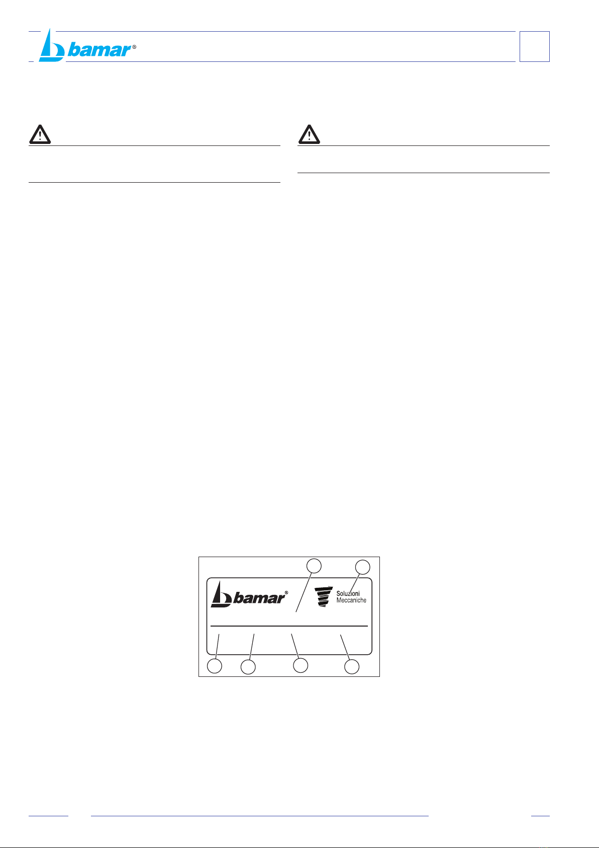
A-3.3 Identification plate ................................................................ 4
A-4 Packaging and content......................................................... 5
A-5 Receipt of goods .................................................................. 5
A-6 Basic tools............................................................................ 5
A-7 Description of the equipment ............................................... 6
A-8 Technical data ...................................................................... 6
A-9 Proper use............................................................................ 7
A-10 Wrong use............................................................................ 7
B SAFETY ............................................................................... 8
B-1 General indications .............................................................. 8
C INSTALLATION ................................................................... 9
C-1 Preliminary operations ......................................................... 9
C-1.1 Stay upper terminal .............................................................. 9
C-1.2 Stay lower terminal............................................................... 9
C-1.3 Stay accessories (optional) ................................................ 10
C-1.4 Chain plate ......................................................................... 10
C-2 How to determine quantity and length of foils .................... 11
C-3 How to prepare the foils ..................................................... 12
C-3.1 Cutting the foil to measure ................................................. 12
C-3.2 Drilling the foil..................................................................... 12
C-3.3 The halyard ........................................................................ 12
C-4 How to install the furler with grounded stay ....................... 13
C-4.1 Fitting splice pieces and half bearings ............................... 13
C-4.2 Fitting terminal foil, fixed head and halyard........................ 14
C-4.3 How to assemble middle foils............................................. 14
C-4.4 Fitting the hoisting foil ........................................................ 15
C-5 How to install the furler onboard ........................................ 15
C-6 How to adjust the turnbuckle.............................................. 15
C-7 How to install the furler on armed mast.............................. 16
C-8 How to hoist the sail ........................................................... 16
C-9 How to fit the furling line to the drum.................................. 16
C-10 The furling line and its leading blocks (optional) ................ 17
C-11 How to use the furler .......................................................... 17
D MANUTENZIONE .............................................................. 18
D-1 Maintenance....................................................................... 18
D-2 Maintenance levels ............................................................ 18
D-3 Maintenance programme ................................................... 19
D-3.1 Cleaning and washing........................................................ 19
D-3.2 Long inactivity .................................................................... 19
D-3.3 Visual check ....................................................................... 19
D-3.4 Repair................................................................................. 19
D-4 Troubleshooting.................................................................. 20
E SPARE PARTS .................................................................. 21
E-1 Drum spare parts ............................................................... 21
E-2 Foils spare parts................................................................. 22
WARRANTY....................................................................... 23
A INFORMAZIONI GENERALI ............................................... 3
Introduzione ......................................................................... 3
A-1 Simbologia presente nel manuale........................................ 3
A-2 Assistenza............................................................................ 4
A-3 Dati di identificazione ........................................................... 4
A-3.1 Modello e tipo....................................................................... 4
A-3.2 Costruttore ........................................................................... 4
A-3.3 Targhetta di identificazione................................................... 4
A-4 Imballo e contenuto.............................................................. 5
A-5 Ricevimento del materiale.................................................... 5
A-6 Attrezzatura minima necessaria........................................... 5
A-7 Descrizione dell’apparecchiatura ......................................... 6
A-8 Dati tecnici............................................................................ 6
A-9 Impieghi ammessi ................................................................ 7
A-10 Uso improprio....................................................................... 7
B SICUREZZA......................................................................... 8
B-1 Indicazioni generali .............................................................. 8
C ISTRUZIONI DI MONTAGGIO............................................. 9
C-1 Operazioni preliminari .......................................................... 9
C-1.1 Terminale superiore dello stallo............................................ 9
C-1.2 Terminale inferiore dello stallo.............................................. 9
C-1.3 Accessori per lo strallo (opzionali) ..................................... 10
C-1.4 Landa di prua ..................................................................... 10
C-2 Determinazione della quantità e della lunghezza dei profili 11
C-3 Preparazione al montaggio profili....................................... 12
C-3.1 Taglio a misura del profilo .................................................. 12
C-3.2 Foratura del profilo............................................................. 12
C-3.3 Percorso della drizza.......................................................... 12
C-4 Montaggio dell’avvolgifiocco con strallo a terra.................. 13
C-4.1 Metodo di montaggio dei giunti e dei rinforzi...................... 13
C-4.2 Montaggio del profilo terminale, della testa fissa
e della drizza ...................................................................... 14
C-4.3 Montaggio dei profili intermedi ........................................... 14
C-4.4 Montaggio del profilo inferitore........................................... 15
C-5 Montaggio dell’avvolgifiocco in testa d’albero.................... 15
C-6 Regolazione del tenditore dello strallo ............................... 15
C-7 Montaggio dell’avvolgifiocco con albero armato ................ 16
C-8 Montaggio della vela .......................................................... 16
C-9 Montaggio della cima sul tamburo ..................................... 16
C-10 Esempio di percorso di cima e relativi bozzelli
di rinvio (opzionali) ............................................................. 17
C-11 Uso dell’avvolgifiocco......................................................... 17
D MANUTENZIONE .............................................................. 18
D-1 Manutenzione..................................................................... 18
D-2 Livelli di manutenzione....................................................... 18
D-3 Programma di manutenzione............................................. 19
D-3.1 Pulizia e lavaggio ............................................................... 19
D-3.2 Lunghi periodi di inutilizzo.................................................. 19
D-3.3 Verifiche visive ................................................................... 19
D-3.4 Interventi di riparazione...................................................... 19
D-4 Inconvenienti - cause - rimedi ............................................ 20
E PARTI DI RICAMBIO......................................................... 21
E-1 Parti di ricambio tamburo ................................................... 21
E-2 Parti di ricambio profili........................................................ 22
GARANZIA ........................................................................ 23
© Copyright Soluzioni Meccaniche srl
Tutti i diritti riservati
Stampato in Italia
Realizzazione: Soluzioni Meccaniche srl - Forlì
Questo manuale o parti di esso non possono essere riprodotti, copiati o
divulgati con qualsiasi mezzo senza la preventiva autorizzazione scritta
della ditta Soluzioni Meccaniche srl.
La ditta Soluzioni Meccaniche srl si riserva il diritto di apportare in qualsiasi
momento tutte le modiche che riterrà opportune, nella costante ricerca
di migliorare la qualità e la sicurezza delle attrezzature, senza impegnarsi
ad aggiornare di volta in volta questa pubblicazione.
© Copyright Soluzioni Meccaniche srl
All rights reserved
Printed in Italy
Realization: Soluzioni Meccaniche srl - Forlì
No part of this manual may be reproduced, copied or transmitted in
any form, or by any means without permission in writing from Soluzioni
Meccaniche srl.
Soluzioni Meccaniche srl has the right to make any changes they think
necessary in order to improve the quality and safety of the systems,
without being obliged to revise this publication every time.

INFORMAZIONI GENERALI
GENERAL INFORMATION
A
3
um_gfm C0_it-en_rev. 1.0
INTRODUZIONE
Questo manuale è stato realizzato allo scopo di fornire tutte le informazioni
necessarie per installare ed utilizzare l’apparecchiatura in maniera
corretta e sicura e per effettuarne la manutenzione.
Occorre leggere e capire questo manuale
prima di usare l’apparecchiatura,
ed effettuare qualsiasi operazione
con esso o su di esso.
Il manuale è suddiviso in sezioni, capitoli e paragrafi in modo da
presentare le informazioni strutturate in modo chiaro.
Le pagine sono numerate progressivamente.
La ricerca delle informazioni può essere basata sull’utilizzo delle parole
chiave usate come titolo delle sezioni e dei capitoli ma soprattutto dalla
consultazione dell’indice generale.
Conservare questo manuale anche dopo la completa lettura, in modo
che sia sempre a portata di mano per il chiarimento di eventuali dubbi.
In caso di problemi nella comprensione di questo manuale o di parti di
esso si raccomanda vivamente di contattare la ditta Soluzioni Meccaniche
srl: indirizzi, numeri di telefono e telefax sono riportati nella quarta di
copertina di questo manuale.
La ditta Soluzioni Meccaniche srl declina ogni responsabilità
per danni a persone o cose derivanti da un uso improprio
dell’attrezzatura, da imperizia, imprudenza o negligenza e dalla
inosservanza delle norme descritte in questo manuale.
A-1 SIMBOLOGIA PRESENTE NEL MANUALE
In questo manuale sono utilizzati cinque tipi di “simboli grafici di
sicurezza”, che hanno lo scopo di evidenziare altrettanti livelli di pericolo
o informazione:
PERICOLO
PERICOLO DI FOLGORAZIONE
ATTENZIONE
AVVERTENZA
RISPETTA L'AMBIENTE
Richiama l’attenzione a situazioni o problemi che potrebbero pregiudicare
l’incolumità delle persone per infortuni o rischio di morte.
PERICOLO
PERICOLO DI FOLGORAZIONE
ATTENZIONE
AVVERTENZA
RISPETTA L'AMBIENTE
Richiama l’attenzione ad una situazione di grave pericolo che potrebbe
pregiudicare l’incolumità delle persone esposte no a possibili rischi di
morte dovuti alla presenza di tensione.
PERICOLO
PERICOLO DI FOLGORAZIONE
ATTENZIONE
AVVERTENZA
RISPETTA L'AMBIENTE
Richiama l’attenzione a situazioni o problemi connessi con l’efcienza
della macchina che non pregiudicano la sicurezza delle persone.
PERICOLO
PERICOLO DI FOLGORAZIONE
ATTENZIONE
AVVERTENZA
RISPETTA L'AMBIENTE
Richiama l’attenzione a importanti informazioni di carattere generale che
non pregiudicano né la sicurezza personale, né il buon funzionamento
della macchina.
PERICOLO
PERICOLO DI FOLGORAZIONE
ATTENZIONE
AVVERTENZA
RISPETTA L'AMBIENTE
Per attirare l’attenzione verso importanti informazioni per il rispetto
dell’ambiente.
INTRODUCTION
This manual has been realised in order to supply all required information
for a correct and safe installation, use and maintenance of the equipment.
You have to read and
understand this manual before using
the equipment and carrying out any
operation on it.
This manual has been divided into sections, chapters and paragraphs in
order to present the information in a structured and clear way.
Pages are numbered progressively.
The search for information may be done either through the key words used
as titles for the sections, or through the consultation of the general index.
Keep this manual at hand even after having read it, it may help clarify
any doubt.
Should you have problems in understanding this manual or parts of it,
we strongly recommend contacting Soluzioni Meccaniche srl: address,
phone and fax number can be found on the cover.
Soluzioni Meccaniche srl declines any and every responsibility
for damages to persons or things caused by either an improper
use of the system or inexperience, negligence, imprudence, or
non-compliance with this manual.
A-1 SYMBOLS TO BE FOUND IN THE MANUAL
Five “graphic safety symbols” are used in this manual. Their purpose is
to highlight different levels of danger and/or information:
DANGER
DANGER OF ELECTROCUTION
CAUTION
WARNING
RESPECT THE ENVIRONMENT
Draws one’s attention to situations or problems that might endanger the
safety of persons, causing the risk of accident and death.
DANGER
DANGER OF ELECTROCUTION
CAUTION
WARNING
RESPECT THE ENVIRONMENT
Draws one’s attention to a highly dangerous situation that might endanger
the safety and life of exposed persons due to the presence of electricity.
DANGER
DANGER OF ELECTROCUTION
CAUTION
WARNING
RESPECT THE ENVIRONMENT
Draws one’s attention to situations or problems linked to the system’s
efciency which do not endanger the safety of people.
DANGER
DANGER OF ELECTROCUTION
CAUTION
WARNING
RESPECT THE ENVIRONMENT
Draws one’s attention to important general information that endangers
neither personal safety nor the operation of the system.
DANGER
DANGER OF ELECTROCUTION
CAUTION
WARNING
RESPECT THE ENVIRONMENT
Draws one’s attention to important pieces of information concerning
respect for the environment.

A
INFORMAZIONI GENERALI
GENERAL INFORMATION
4um_gfm C0_it-en_rev. 1.0
A-2 ASSISTENZA
Qualora ci siano dubbi sull’utilizzo o la manutenzione dell’apparecchiatura,
consigliamo di contattare la ditta Soluzioni Meccaniche srl.
PERICOLO
PERICOLO DI FOLGORAZIONE
ATTENZIONE
AVVERTENZA
RISPETTA L'AMBIENTE
Nessuna modica deve essere apportata all’apparecchiatura senza
l’autorizzazione di Soluzioni Meccaniche srl, in quanto può comportare
pericoli.
A-3 DATI DI IDENTIFICAZIONE
Vericare che il manuale sia corrispondente alla macchina a cui si fa
riferimento. Nel caso di richieste di informazione o di assistenza tecnica,
è necessario specicare, oltre al modello e tipo di apparecchiatura, anche
il numero di matricola rilevabile dalla targhetta di identicazione posta
su ogni apparecchiatura.
A-3.1 Modello e tipo
Avvolgiocco manuale tipo GFM:
• C0
A-3.2 Costruttore
Soluzioni Meccaniche srl
Via F.lli Lumière 45
47122 FORLI’ - ITALY
Tel. +39 0543 463311
Fax. +39 0543 783319
www.bamar.it
info@bamar.it
A-3.3 Targhetta di identicazione
La targhetta di identicazione realizzata in alluminio adesivo con fondo
argento viene applicata direttamente sull’apparecchiatura.
In essa sono riportati i dati identicativi dell’apparecchiatura e del
costruttore:
A. Nome del costruttore
B. Dati costruttore
C. Anno di costruzione
D. Numero di revisione
E. Numero seriale
F. Codice
A-2 AFTER-SALES SERVICE
Should you have any doubt concerning either the use or maintenance of
the equipment, we suggest contacting Soluzioni Meccaniche srl.
DANGER
DANGER OF ELECTROCUTION
CAUTION
WARNING
RESPECT THE ENVIRONMENT
The equipment cannot be modified in any way without the prior
authorization from Soluzioni Meccaniche srl, as this may be dangerous.
A-3 IDENTIFICATION DATA
Please check the instruction manual corresponds to the equipment
we are referring to. Should you need further information or technical
assistance, you have to specify not only model and type of equipment,
but also the serial number that you may nd on the identication plate
placed on every device.
A-3.1 Model and type
Electric foresail furler type GFM:
• C0
A-3.2 Manufacturer
Soluzioni Meccaniche srl
Via F.lli Lumière 45
47122 FORLI’ - ITALY
Tel. +39 0543 463311
Fax. +39 0543 783319
www.bamar.it
info@bamar.it
A-3.3 Identication plate
The identification plate is made in adhesive aluminium with silver
background. It is tted directly onto the equipment.
The plate presents the identification data of both equipment and
manufacturer:
A. Name of manufacturer
B. Manufacturer data
C. Year of production
D. Number of revision
E. Serial number
F. Code
Via F.lli Lumière 45 - 47122 Forlì (FC) - ITALIA
Tel. +39 0543 463311
bamar.it
info@bamar.it
REV SNAnno Codice
A
B
CDEF

INFORMAZIONI GENERALI
GENERAL INFORMATION
A
5
um_gfm C0_it-en_rev. 1.0
A-4 IMBALLO E CONTENUTO
Gli avvolgi occo manuali vengono forniti, completi degli accessori per il
montaggio, in due robuste scatole di cartone, sovrapponibili, di peso e
dimensioni variabili in funzione del modello e della lunghezza richiesta.
La confezione contiene:
A- n.1 Libretto istruzioni
B - n.* Pro lo intermedio L= 1500 mm
C - n.1 Pro lo inferitore L= 750 mm
D - n.1 Tamburo avvolgi occo
E- n.3 Anime di rinforzo (senza fermo)
F- n.* Anime di giunzione (con fermo)
G- n.* Boccole di scorrimento
H - n.1 Liquido frena letti
I- n.1 Chiave esagonale
J - n.* Viti per ssaggio giunti
K - n.1 Testa ssa
L- n.1 Gambetti
A-4 PACKAGING AND CONTENT
The manual foresail furling and ree ng systems together with all their
accessories for the installation are supplied in two strong cardboard
boxes of variable weight and dimensions depending on model and length.
The boxes contain:
A- n.1 Instruction manual
B- n.*Middle foils L= 15000 mm
C- n.1 Furler's drum
D- n.1 Hoisting foil L= 750 mm
E- n.3 Splice pieces (without clutch)
F- n.*Splice pieces (with clutch)
G- n.*Half bearings
H- n.1 Sealing liquid tube
I- n.1. Allen wrench
J- n.* Screws for xing splice pieces
K- n.1 Fixed head
L- n.1 Shackles
* quantità variabile a seconda della lunghezza richiesta
A-5 RICEVIMENTO DEL MATERIALE
Dimensioni e peso dell'imballo
PERICOLO
PERICOLO DI FOLGORAZIONE
ATTENZIONE
AVVERTENZA
RISPETTA L'AMBIENTE
Le dimensioni ed il peso dell’imballo cambiano a seconda del contenuto
della scatola.
La merce viaggia a rischio e pericolo del destinatario. Egli ha il dovere di
eseguire una completa veri ca di quanto ricevuto, emettere tutte le riserve,
se necessario esercitare tutti i ricorsi al trasportatore nei termini e nei modi
regolamentari.
A-6 ATTREZZATURA MINIMA NECESSARIA
PERICOLO
PERICOLO DI FOLGORAZIONE
ATTENZIONE
AVVERTENZA
RISPETTA L'AMBIENTE
Evitare nel modo più assoluto di dare corso al montaggio senza avere a
disposizione l’attrezzatura necessaria. Il procedere con attrezzi di fortuna
può, oltreché danneggiare irreparabilmente l’apparecchiatura, risultare
pericoloso per l’incolumità generale.
Prima di iniziare le operazioni di montaggio è bene accertarsi di disporre
di una serie di attrezzi, di seguito elencati, quale attrezzatura minima
necessaria:
• Cacciavite con testa a croce ø 5 mm
• Martello di plastica
• Pinza
• Punta da segno
• Trapano elettrico con mandrino per punte elicoidali ø 7 mm
• Seghetto a mano con lama per taglio di metalli
• Lima a taglio ne
• Punte elicoidali per la foratura di metallo:
ø 4,25 - ø 5 - ø 7 mm per C0
• Maschi per lettare:
M5 per C0
* quantity depending on length required
A-5 RECEIPT OF GOODS
Packaging dimensions and weight
DANGER
DANGER OF ELECTROCUTION
CAUTION
WARNING
RESPECT THE ENVIRONMENT
Packaging weight and dimensions vary depending on box content.
The goods are shipped at the receiver’s own risk. The purchaser will
have to check the goods carefully and should claim from the carrier in
the due terms.
A-6 BASIC TOOLS
DANGER
DANGER OF ELECTROCUTION
CAUTION
WARNING
RESPECT THE ENVIRONMENT
Avoid starting to assemble the equipment without the required tools.
Proceeding with the wrong tools may not only irremediably damage the
system, but also be dangerous for general safety.
Before starting to assemble the system make sure you have the following
basic series of tools:
• Star screw driver ø 5 mm
• Plastic hammer
• A pair of pliers
• Mark bit
• Electric drill with mandrel for ø 7 mm. drill bits
• Hand metal saw
• Smooth le
• Drill bits for drilling metal:
ø 4,25 - ø 5 – ø 7 mm for C0
• Taps:
M5 for C0
B
C
D
E*
I
H
K
J
F*
G*
A
L

A
INFORMAZIONI GENERALI
GENERAL INFORMATION
6um_gfm C0_it-en_rev. 1.0
A-7 DESCRIZIONE DELL’APPARECCHIATURA
L'avvolgiocco manuale può essere applicato su imbarcazioni con
lunghezza massima indicativa pari a 8 metri (26 piedi), supercie velica
non superiore a 27m2e con strallo compreso tra ø 4 e 7 mm.
Viene montato agevolmente sia con strallo a terra che con strallo armato
sull'imbarcazione. Si richiede particolare destrezza all'operatore che
dovrà essere coadiuvato da almeno un altro addetto.
Nel presente manuale viene descritto il metodo di montaggio con strallo
a terra ed alcune informazioni per il montaggio con strallo armato.
A-8 DATI TECNICI
Ref C0
ø r 4-7
Max Vela(150%) - Max Sail(150%) m227
LFT max m 8
ø l Utile int. prof. 13
A 25
B 40
C 120
D 860
E 482
F 340
G 300
H 2,5
ø I 16
ø J 132
ø K 110
L 97
M 70
N 100
O 130
P 160
Q 190
R 28
S 30
T 370
U 750
V 27
W 15
ø a 8
ø b 58
ø c 30
Prolo - Foil kg/m 0,66
Tamburo - Drum kg 1,95
Perni per landa - Special clevis pins
A-7 DESCRIPTION OF THE EQUIPMENT
The manual foresail furling and reeng system can be applied on boats
up to 8 mt. length (26 feet), sail area up to 27 sq.mt. and with a stay
from ø 4 to ø 7 mm.
It can easily be assembled both with grounded stay and with stay armed
on the boat. Special skills are required and the operator has to be helped
at least by another person. This manual describes how to assemble
the furler with stay on the ground, but it gives also some information
concerning the operation with armed stay.
A-8 TECHNICAL DATA
A
ø a
ø J
ø K
ø b
L
QPOTM
ø c
H H
R
W
S
C
D
T
G
F
EV
Uø I
ø r
B
A
B
D
C
ø
e
ø d
f
g
h
g
Codice
Code
Strallo - Wire
ø mm
f
mm
g
mm
h
mm
ø e ø d
mm
901100505 4÷5 28 11 50 M8 8
901100510 6÷7 28 11 50 M8 10,8
Sezione prolo connettore e boccola di rotolamento
Foil and splice piece bush section
BMG 30R
sezione - section AxB 23x30 mm
canaletta - sail groove CØ 7 mm
apertura - gap D3,5 mm

INFORMAZIONI GENERALI
GENERAL INFORMATION
A
7
um_gfm C0_it-en_rev. 1.0
A-9 IMPIEGHI AMMESSI
L'avvolgiocco manuale è una specica attrezzatura per l'avvolgimento
della vela di prua su imbarcazioni da diporto o da crociera. È stato
progettato e realizzato in unico modello e può essere applicato su
imbarcazioni di max 26 piedi di lunghezza o con supercie velica di 27
m2 MAX.
Qualsiasi altro impiego viene considerato contrario all'uso previsto e
pertanto improprio.
La conformità ed il rigoroso rispetto delle condizioni d'uso, manutenzione
e riparazione specicate dal costruttore, costituiscono una componente
essenziale dell'uso previsto.
L'uso, la manutenzione e la riparazione dell'avvolgiocco debbono essere
afdate esclusivamente a persone a conoscenza delle sue peculiarità e
delle relative procedure di sicurezza.
È inoltre necessario che siano rispettate tutte le norme antinfortunistiche
e le norme generalmente riconosciute per la sicurezza e la medicina
del lavoro.
A-10 USO IMPROPRIO
Per uso improprio si intende l’uso dell’apparecchiatura secondo criteri di
lavoro non conformi alle istruzioni contenute in questo manuale e che,
comunque, risultassero pericolosi per sè e per gli altri.
A-9 PROPER USE
The manual foresail furling system is to be used for furling and reeng
foresails on cruising boats. It has been designed and realized in one
single model and can be tted on boats up to 26 feet with sail area of
27 square metres max.
Any other use is considered as contrary to the proper use and therefore
not allowed.
The conformity and the rigorous respect of the conditions of use,
maintenance and repair specied by the manufacturer, are an essential
component of the proper use.
The use, maintenance and repair of the furler have to be carried out
exclusively by people who know its peculiarities and its safety procedures.
Moreover, all safety rules have to be followed.
A-10 WRONG USE
Wrong use indicates the use of the device following working criteria that
do not correspond to the instructions presented in this manual and that
might be dangerous for the operator himself and other people.

B
SICUREZZA
SAFETY
8um_gfm C0_it-en_rev. 1.0
B-1 GENERAL INDICATIONS
This chapter summarises the general safety indications that will be
integrated in the following chapters by specic tips when necessary.
Though the system is very simple to assemble and use, some basic safety
rules have to be followed. These rules will grant both the safety of the
operator and the correct use of the product for its best preservation in time.
DANGER
DANGER OF ELECTROCUTION
CAUTION
WARNING
RESPECT THE ENVIRONMENT
If the furler is assembled on an armed mast the co-operation of two
operators is required.The operator who works on the mast head needs
an adequate safety harness to prevent him from falling
• Carefully read and understand the instruction manual before installing
and starting the furler.
• The equipment must never be used by children, and must not be
employed for uses that are not contemplated in this manual.
• Should you work on an armed mast, you do not require any special
outt apart from a safety harness. The only general rule to be followed
is the use of comfortable and practical clothes which do not hinder
movements.
• Always keep this manual handy. Read it carefully in order to learn
the instructions for both installation and use.
• Do not allow people who do not have the necessary knowledge to
use the system.
• Carry out the installation and maintenance in optimal conditions of
visibility and in areas that are suitable for all necessary operations
both for climate and collocation of the plane of work.
• Should the interventions be inevitably executed onboard, carry them
out only when the conditions can grant the highest safety.
• Do not carry out the installation in case of strong wind or rainstorm.
• Do not execute any intervention in presence of persons that for
either age or psycho-physical conditions can not grant the necessary
common sense.
B-1 INDICAZIONI GENERALI
Questo capitolo riassume le indicazioni di sicurezza di carattere generale
che saranno integrate, nei capitoli seguenti, da speciche avvertenze
ogni qualvolta dovesse risultare necessario.
Nonostante l’estrema semplicità delle operazioni di montaggio e la
facilità nell’uso dell’attrezzatura, è opportuno che vengano rispettate
alcune elementari norme di sicurezza. Queste norme garantiranno, oltre
all’incolumità sica dell’operatore, un corretto uso del prodotto ed una
sua ottimale resa nel tempo.
PERICOLO
PERICOLO DI FOLGORAZIONE
ATTENZIONE
AVVERTENZA
RISPETTA L'AMBIENTE
Nel caso in cui il montaggio dell’avvolgifocco sia effettuato su di un albero
già armato sull’imbarcazione è necessario l’intervento di almeno due
operatori. L’operatore destinato ad intervenire in testa d’albero dovrà
essere munito di adeguata imbragatura di sicurezza (“banzigo”) contro
il rischio di cadute
• Leggere attentamente e comprendere le istruzioni per l’uso prima di
procedere all’installazione ed alla messa in funzione dell’attrezzatura.
• L’attrezzatura non deve in alcun modo essere utilizzato da bambini
o per impieghi diversi da quelli specicati nel presente manuale.
• Oltre all’imbragatura di sicurezza (nel caso si operi in testa dell’albero
già armato sull’imbarcazione) non sono necessari particolari
indumenti. Resta come norma di carattere generale quella di munirsi
di un abbigliamento comodo, pratico e che non tenda ad impedire i
movimenti degli arti.
• Tenere questo manuale sempre a portata di mano e conservarlo con
cura. Leggerlo attentamente per apprenderne le istruzioni relative sia
al montaggio che all’uso.
• Evitare che persone non a conoscenza delle necessarie informazioni
possano intervenire sull’attrezzatura.
• Eseguire le operazioni di montaggio e manutenzione in condizioni
ottimali di visibilità ed in ambienti che, per clima e collocazione
ergonomica del piano di lavoro, possano risultare idonei allo
svolgimento di tutte le operazioni necessarie.
• Qualora gli interventi debbano necessariamente avvenire
sull’imbarcazione, effettuarli soltanto quando le condizioni climatiche
possano garantire la massima sicurezza.
• Non eseguire l’installazione in caso di forte vento o di temporali
• Non eseguire mai alcun intervento (operativo o manutentivo) in
presenza di persone che per età o condizione psicosica non siano
in grado di garantire il necessario buonsenso.

ISTRUZIONI DI MONTAGGIO E USO
INSTALLATION AND USE
C
9
um_gfm C0_it-en_rev. 1.0
C-1 OPERAZIONI PRELIMINARI
Aprire gli imballi e vericare che la dotazione di materiali e minuterie
sia completa.
PERICOLO
PERICOLO DI FOLGORAZIONE
ATTENZIONE
AVVERTENZA
RISPETTA L'AMBIENTE
Provvedere allo smaltimento dell’attrezzatura secondo le normative
vigenti nei vari paesi.
PERICOLO
PERICOLO DI FOLGORAZIONE
ATTENZIONE
AVVERTENZA
RISPETTA L'AMBIENTE
Prima di procedere all’installazione dell’avvolgiocco vericate o fate
vericare da persona competente che lo strallo sia in buone condizioni.
In caso di dubbio è consigliabile sostituirlo.
C-1.1 Terminale superiore dello stallo
Non tutti i terminali superiori degli stralli sono idonei al montaggio di un
avvolgiocco per cui si rendono necessarie alcune modiche allo strallo
nel caso in cui si effettui il montaggio con strallo a terra.
• Terminali a sfera(principalmente presenti su alberi Isomat e
Z-spars).
Occorre inserire un terminale a sfera-occhio tipo Acmo EB o
equivalenti in testa d’albero, accorciare il cavo tenendo conto della
lunghezza del nuovo pezzo ed aggiungere un nuovo terminale a
pressare sullo strallo.
• Terminali a T(principalmente presenti su alberi Kemp, Selden,
Nemo, Sparcraft con sartiame frazionato). Occorre modicare
l’ancoraggio dello strallo sull’albero per poter impiegare un terminale
a pressare con snodo.
C-1.2 Terminale inferiore dello stallo
PERICOLO
PERICOLO DI FOLGORAZIONE
ATTENZIONE
AVVERTENZA
RISPETTA L'AMBIENTE
SU STRALLI ESISTENTI: Prima di iniziare l’installazione marcare sullo
strallo la posizione di regolazione del tenditore (se previsto) e/o la
posizione dell’occhio inferiore dello strallo tra le lande.
CON UNO STRALLO NUOVO: montare lo strallo sull’imbarcazione,
eseguire la regolazione del tenditore e marcarne la regolazione e/o la
posizione sulle lande.
Se lo strallo è munito, alla sua estremità verso coperta, di un cannotto
lettato a pressare di tipo commerciale, non ci saranno difcoltà a
far scorrere questo elemento all’intemo dei proli dell’avvolgiocco.
Diversamente, con terminali più ingombranti, vericare che le dimensioni
del terminale non siano superiori a quelle del diametro interno dei proli
(vedi A-8). In questo caso sarà necessario eliminare il terminale e
ripiombare, dopo il montaggio dei proli, con un terminale rapido tipo
STA-LOK® (vedi C-1.3).
C-1 PRELIMINARY OPERATIONS
Open all boxes and check the list of materials is complete.
DANGER
DANGER OF ELECTROCUTION
CAUTION
WARNING
RESPECT THE ENVIRONMENT
Dispose of the equipment following the rules in force in the different
countries.
DANGER
DANGER OF ELECTROCUTION
CAUTION
WARNING
RESPECT THE ENVIRONMENT
Before installing the furler, check the stay is in good conditions. In case
of doubt we suggest replacing it.
C-1.1 Stay upper terminal
Not all upper terminals are suitable for the tting of foresail furling and
reeng system, therefore some modications to the stay are necessary
if the installation has to be carried out with grounded stay.
• Ball terminals (mainly present on Isomat and Z-spars masts).
You will have to add a ball-eye terminal (Acmo EB type) or similar
on the mast head, shorten the stay keeping in mind the length of the
new piece and add a new swage terminal to the stay.
• T terminals (mainly on Kemp, Selden, Nemo, Sparcraft masts with
fractional rig).You need to modify the stay connection to the mast in
order to use a toggle swage terminal.
C-1.2 Stay lower terminal
DANGER
DANGER OF ELECTROCUTION
CAUTION
WARNING
RESPECT THE ENVIRONMENT
ON EXISTING STAYS: before starting the installation, mark the position
of the turnbuckle (if any) on the stay, and/or the position of the stay lower
eye terminal between the link plates.
ON A NEW STAY: install the stay on to the mast, adjust the turnbuckle
and mark the adjustment and/or the position on the link plates.
If the forestay is supplied with a standard swage threaded terminal on
its lower end, there will be no problem in letting this element slide inside
the furler foils. On the contrary, with bigger terminal, check the terminal
dimensions are not bigger than the foil internal diameter (see A-8). In
this case, you will have to take off the terminal and replace it with a rapid
terminal (Stalok type, see C-1.3) after having installed the foils.

C
ISTRUZIONI DI MONTAGGIO E USO
INSTALLATION AND USE
10 um_gfm C0_it-en_rev. 1.0
C-1.3 Accessori per lo strallo (opzionali)
Terminali ed accessori speciali per la semplicazione dell’installazione:
1. Tenditore snodato con asta filettata con attacco rapido STA-LOK®
per strallo
2. Asta filettata lunga con attacco rapido STA-LOK®
3. Asta filettata corta con attacco rapido STA-LOK®
4. Terminale ad occhio con attacco rapido STA-LOK®
5. Snodo (ricavato da barra)
6. Perno speciale
C-1.3 Stay accessories (optional)
Terminals and special accessories which make the installation easier:
1. STA-LOK®toggle turnbuckle
2. STA-LOK®long threaded stud with
3. STA-LOK®SHORT threaded
4. STA-LOK®Eye terminal
5. Bar toggle
6. Special clevis pin
34
2
1
C-1.4 Landa di prua
Il tamburo dell’avvolgiocco deve essere ancorato alla landa di prua
tramite il bullone fornito standard.
Nel caso non sia possibile tale applicazione richiedere il perno speciale
specicando il diametro del perno.
La posizione di attacco deve essere scelta in funzione di:
• Manovrabilità del braccio ancora
• Sicurezza in navigazione: con vela alta è possibile traguardare la
prua in navigazione
• Possibilità di alloggiare all’interno il tenditore,previa verica degli
ingombri del tenditore.
C-1.4 Chain plate
The furler drum has to be connected to the chain plate by means of a
standard clevis pin (supplied).
Should this application not be possible, you will have to order the special
clevis pin and specify its diameter.
The anchoring position has to be chosen depending on:
• Handling of the anchor
• Safety while cruising: with a high sail you may see over the bow.
• Possibility of lodging the turnbuckle inside the furler, after having
checked its dimensions.
Bullone
stantard
Perno
speciale
Perno
speciale
Standard
clevis pin
Special
clevis pin
Special
clevis pin
5
6

ISTRUZIONI DI MONTAGGIO E USO
INSTALLATION AND USE
C
11
um_gfm C0_it-en_rev. 1.0
C-2 DETERMINAZIONE DELLA QUANTITÀ E
DELLA LUNGHEZZA DEI PROFILI
Al ne di poter determinare la quantità dei proli necessari occorre, dopo
aver denito la posizione di attacco sulla landa del corpo motoriduttore,
procedere come segue:
• Vericare la lunghezza Adello strallo dal centro del foro di attacco
sulla landa alla piombatura del terminale superiore
• Scegliere nella tabella della pagina seguente la misura Win funzione
del foro utilizzato sulla landa
• Applicare la seguente formula:
A-(W+X+50)
1500 = Numero dei proli A-(W+X+50)
1500 = Number of foils
Dove:
A è lunghezza dello strallo misurata dal centro del foro di attacco
sulla landa alla piombatura del terminale superiore
W è la misura dal centro del foro di attacco sulla landa alla base
di partenza del prolo inferitore
X è la lunghezza del prolo inferitore
50 Distanza ssa tra terminale e piombatura strallo per avvolgiocco
C0
1500 Lunghezza di un prolo intermedio
Vediamo un esempio pratico:
• Lunghezza Adello strallo 12800 mm
• Modello di avvolgiocco C0
• Lunghezza Wavendo scelto il 3°
foro di attacco alla landa 310 mm
Applichiamo la formula:
12800-(310+750+50)
1500 = 7,79
N° Proli
79% della lunghezza
di un prolo
12800-(310+750+50)
1500 = 7,79
N° Foils
79% of length
of a foil
Si dovranno quindi utilizzare 7 proli interi ed accorciare un ottavo prolo
alla lunghezza di 1185 mm.
Vedere il capitolo C-3 Preparazione al montaggio per la corretta
procedura per il taglio del prolo.
C-2 HOW TO DETERMINE QUANTITY AND
LENGTH OF FOILS
In order to determine the number of foils required, you must proceed as
follows, after having dened the connection on the link plates.
• Check the stay length A, from the connection pin hole on the link
plate, to the upper terminal swaging.
• On the next page you will nd a table concerning the furler measures.
Find out the length of Won your furler depending on the hole you
will use on the link plate
• Apply the following formula:
Where:
A Is the length of the stay from the connection pin hole on the
plate to the upper terminal swaging.
W Is the measure from the centre of the connection pin hole on
the plate to the beginning of the hoisting foil.
X Is the length of the hoisting foil
50 Fixed distance from terminal to stay swage for C0.
1500 Length of a middle foil.
Let’s see a practical example:
• Length of the stay A 12800 mm
• Furler model C0
• Length of Whaving chosen
the rst hole on the link plate 310 mm
Now, let’s apply the formula:
This means you will have to use 7 foils and cut the 8th one to length
(1185 mm.)
Please, see the section C-3 How to prepare the foil’s for the correct
procedure when cutting the foil.
X
Y
Z
W
A
W2
W
1W3W5
W4
X = 750 mm **
Z = Prolo intermedio adattato a misura
Middle foil to be cut to measure
Y = Prolo intermedio 1,5m x quantità necessaria
Middle foil 1.5m x quantity required
** Misura ssa
** Fixed measure
A-(W+X+50)
1500 =Numero dei proli
Number of foils
Mod: C0
W1mm 370
W2mm 340
W3mm 310
W4mm 280
W2mm 250

C
ISTRUZIONI DI MONTAGGIO E USO
INSTALLATION AND USE
12 um_gfm C0_it-en_rev. 1.0
C-3 PREPARAZIONE AL MONTAGGIO PROFILI
C-3.1 Taglio a misura del prolo
• Tracciare su un prolo la misura ricavata dalla formula dal cap. C.2.
• Forare con una punta ø 7 mm il prolo
• Tagliare con un seghetto a mano il profilo sul centro del foro
precedentemente eseguito
• Con una lima a taglio dolce sbavare le estremità del prolo con
particolare cura le sedi del gratile.
C-3 HOW TO PREPARE THE FOILS
C-3.1 Cutting the foil to measure
• Mark out on a foil the measure you derived from the formula on
chap. C.2.
• Drill the foil with a ø 7 mm drill bit.
• With a hand saw cut the foil on the centre of the hole you drilled
• File the foil end with a smooth le with particular care to the luff groove.
ø 7
SX
DX
C
B
A
A
C-3.2 Foratura del prolo
• Forare e lettare il prolo, per il montaggio dei grani di ssaggio
dell’anima di giunzione, seguendo la tabella sotto riportata.
A B C
C0 15 25 Ø4.25/M5
C-3.2 Drilling the foil
• Drill and thread the foil to house the Allen screws used to hold the
splice pieces. See the table hereafter for measurements:
A B C
C0 15 25 Ø4.25/M5
C-3.3 Percorso della drizza
• Inserire la drizza fornita nel foro inferiore della testa ssa, ruotarla
sulla puleggia di 180° ed entrare all'interno della testa ssa inlandola
nella canaletta lato dx del prolo terminale.
• Aiutarsi con un piccolo cacciavite e far scorrere la cima nelle canalette
di dx di tutti i proli che si andranno ad assemblare no a farla
fuoriuscire dal prolo inferitore (A).
C-3.3 The halyard
• Insert the halyard (supplied) in the lower hole of the xed head, rotate
it by 180° on the pulley and let it slide inside the xed head. Then,
insert the halyard in the right-hand side groove of the terminal foil.
• Help yourself with a small screw-driver and let the halyard slide in
the right-hand side groove of all foils you are assembling, until you
let it get out from the hoisting foil (A).

ISTRUZIONI DI MONTAGGIO E USO
INSTALLATION AND USE
C
13
um_gfm C0_it-en_rev. 1.0
C-4 MONTAGGIO DELL’AVVOLGIFIOCCO CON
STRALLO A TERRA
Smontare lo strallo ed appoggiarlo su una supercie adatta al montaggio
avendo cura di accertarsi che l’avvolgiocco ed i proli non si danneggino
in corso d’opera.
PERICOLO
PERICOLO DI FOLGORAZIONE
ATTENZIONE
AVVERTENZA
RISPETTA L'AMBIENTE
Prima di smontare lo strallo assicurarsi che sia stata applicata una drizza
di sicurezza a prua.
C-4.1 Metodo di montaggio dei giunti e dei rinforzi
Per l’unione dei proli intermedi e per il rinforzo del prolo terminale e
del prolo inferitore procedere come segue:
• Premontare le boccole di scorrimento come evidenziato nelle foto
e nel disegno.
PERICOLO
PERICOLO DI FOLGORAZIONE
ATTENZIONE
AVVERTENZA
RISPETTA L'AMBIENTE
Le anime di rinforzo sono sprovviste del rivetto di fermo nel foro centrale.
C-4 HOW TO INSTALL THE FURLER WITH
GROUNDED STAY
Take down the stay and put it on an even surface. Take care not to damage
neither motorization nor foils during the installation.
DANGER
DANGER OF ELECTROCUTION
CAUTION
WARNING
RESPECT THE ENVIRONMENT
Before taking down the stay make sure you have put a safety halyard
to replace it.
C-4.1 Fitting splice pieces and half bearings
Proceed as follows in order to connect middle foils and reinforce both
terminal and hoisting foil:
• Fit the half bearings before, as highlighted both on photos and
drawing.
DANGER
DANGER OF ELECTROCUTION
CAUTION
WARNING
RESPECT THE ENVIRONMENT
The hoisting and terminal splice pieces are not provided with the clutch
in the central hole.
180°
90°
A

C
ISTRUZIONI DI MONTAGGIO E USO
INSTALLATION AND USE
14 um_gfm C0_it-en_rev. 1.0
C-4.2 Fitting terminal foil, xed
head and halyard
• Insert the xed head on the stay.
You will have to apply a splice piece (without
clutch) on the terminal foil.
How to t the splice piece to the terminal foil:
• Insert the half bearings in the aluminium
piece.
• Now insert the complete splice piece inside
the foil until the holes on the foil and the marks
on the splice piece coincide.
• Put a drop of sealing liquid, then block the
splice piece with the grains.
• Fit the xed head (A).
• Insert the halyard as shown on paragraph
C-3.3.
C-4.2 Montaggio del prolo
terminale, della testa ssa e
della drizza
• Inserire la testa ssa nello strallo.
Sul prolo terminale deve essere applicata l'anima
di rinforzo (senza rivetto di fermo).
Per montare il rinforzo nel terminale:
• Inserire nell'anima in alluminio una boccola
di scorrimento.
• Inserire ora il rinforzo completo nel prolo no
a far coincidere i fori di ssaggio con le tacche
previste sull'anima.
• Mettere una goccia di liquido frenafiletti
quindi ssare l'anima con le viti e la chiave
esagonale fornita.
• Fissare la testa ssa (A).
• Inserire la drizza fornita come descritta al
punto C-3.3.
A
C-4.3 Montaggio dei proli intermedi
I proli intermedi devono essere collegati tra loro
utilizzando un’anima di giunzione (provvista di
rivetto di fermo).
Per montare il giunto tra due proli intermedi:
• Inserire nel giunto in alluminio una boccola
di scorrimento.
• Applicare il giunto con il semiguscio
sullo strallo quindi applicare anche l’altro
semiguscio ruotandolo di 90°.
• Inserire ora il giunto completo nel profilo
intermedio no a mettere in battuta il fermo
del giunto e far coincidere i fori di ssaggio
con le tacche previste sull’anima.
• Mettere una goccia di liquido frenafiletti
quindi ssare l’anima con le viti e la chiave
esagonale fornita.
• Montare tutti i profili necessari avendo
cura di montare come penultimo il prolo
precedentemente tagliato a misura quindi,
per ultimo, il prolo inferitore.
C-4.3 How to assemble middle foils
The middle foils have to be connected by means
of splice pieces (supplied with clutch).
In order to t the splice pieces between two middle
foils you have to:
• Insert one half bearing in the aluminium
element.
• Adapt the splice piece with one half bearing
to the stay, then add the other half bearing.
Rotate the two half bearings by 90°.
• Now insert the complete splice piece in the
middle foil until the holes on the foil and the
marks on the splice piece coincide.
• Put a drop of sealing liquid,then block the
splice piece with the Allen screws.
• Fit all required foils taking care to leave as
second-last the foil that has previously been
cut to measure.The hoisting foil will be tted
as last.

ISTRUZIONI DI MONTAGGIO E USO
INSTALLATION AND USE
C
15
um_gfm C0_it-en_rev. 1.0
C-4.4 Fitting the hoisting foil
• Connect the hoisting foil to the lower middle
foil.
• Fit the splice piece on the hoisting foil.
• Connect the torque tube (part of the drum).
• Put some corrosion inhibitor, like Duralac or
similar, in the holes.
• Insert and tighten the screws (A) with the
Allen wrench.
C-4.4 Montaggio del prolo
inferitore
• Collegare il prolo inferitore sull'ultimo prolo
intermedio.
• Montare l'anima di rinforzo sul profilo
inferitore.
• Montare il cannotto (parte integrante del
tamburo).
• Applicare un poco di pasta anti ossidante tipo
Duralac o simile nei fori di ssaggio.
• Inserire e serrare le viti (A) con la chiave
fornita.
A
C-5 MONTAGGIO
DELL’AVVOLGIFIOCCO IN
TESTA D’ALBERO
• Ricollegare il terminale dello strallo in testa
d’albero utilizzando allo scopo una drizza.
PERICOLO
PERICOLO DI FOLGORAZIONE
ATTENZIONE
AVVERTENZA
RISPETTA L'AMBIENTE
Non eseguire installazioni intesta d’albero in caso
di forte vento.
PERICOLO
PERICOLO DI FOLGORAZIONE
ATTENZIONE
AVVERTENZA
RISPETTA L'AMBIENTE
Non piegare troppo i proli al momento della
installazione sulla barca.
C-6 REGOLAZIONE DEL
TENDITORE DELLO
STRALLO
• Per regolare il tenditore smontare i 3 grani (A)
del tamburo inferitore.
• Sollevare il tamburo e farlo scorrere verso
l’alto sugli estrusi no a scoprire il tenditore
alloggiato all’interno del tamburo.
• Ancorare lo strallo sulla landa di prua
• Regolare e bloccare il tenditore avendo
cura di non accorciarlo oltre la lunghezza
originaria.
• Abbassare il tamburo no a ssare i 3 grani
nella posizione originale
• Fissare le lande del tamburo in funzione del
tipo di montaggio scelto (vedi gure del cap.
C-1.4).
C-5 HOW TO INSTALL THE
FURLER ONBOARD
• Connect the top of the stay to the mast head
using a halyard.
DANGER
DANGER OF ELECTROCUTION
CAUTION
WARNING
RESPECT THE ENVIRONMENT
Do not attempt to install the assembled system
in strong winds
DANGER
DANGER OF ELECTROCUTION
CAUTION
WARNING
RESPECT THE ENVIRONMENT
Make sure not to over bend the foils when
installing the system onboard.
C-6 HOW TO ADJUST THE
TURNBUCKLE
• To adjust the turnbuckle, disassemble the 3
screws (A) from the drum-hoisting foil.
• Lift the drum and let it slide upwards over the
extrusions until the turnbuckle housed inside
the drum is shown.
• Connect the stay to the chain plate.
• Adjust and tighten the turnbuckle, making
sure not to shorten it more than its original
length.
• Slip the drum mechanism down and tighten
the three grains in the original position.
• Tighten the furler's link plates depending on
the kind of installation chosen (see photos
on chapt. C-1.4).
A

C
ISTRUZIONI DI MONTAGGIO E USO
INSTALLATION AND USE
16 um_gfm C0_it-en_rev. 1.0
C-7 MONTAGGIO DELL’AVVOLGIFIOCCO CON
ALBERO ARMATO
In questo caso non è necessario smontare lo strallo,ma è suf ciente
scollegarlo dalla landa di prua per eseguire il montaggio dell’avvolgi occo.
Adottando questa soluzione i pro li non sono sottoposti allo stress
derivato dalla inevitabile essione in fase di installazione dello strallo
sull’albero.
PERICOLO
PERICOLO DI FOLGORAZIONE
ATTENZIONE
AVVERTENZA
RISPETTA L'AMBIENTE
Prima di scollegare lo strallo dalla landa di prua assicurarsi che sia stata
applicata una drizza di sicurezza.
Per eseguire il montaggio seguire la procedura descritta per l’installazione
con strallo a terra adottando alcuni importanti accorgimenti:
• Per evitare che il pro lo montato sullo strallo cada, inserire la testa
girevole e mandarla in battuta sull’anello di fermo.Collegare la drizza
sull’attacco relativo ed una piccola cima per il recupero sull’attacco di
penna.Mettere in tiro la drizza e sollevarla ripetutamente man mano
che i pro li vengono assemblati.Al termine del montaggio recuperare
la testa girevole ammainandola.
C-8 MONTAGGIO DELLA VELA
Per montare la vela occorre:
• Fissare la penna della vela alla drizza fornita.
• Inserire il gratile della vela nell'apertura del pro lo inferitore.
• Issare la vela, ssare le mure al gambetto posto sul tamburo quindi
tesare la drizza strozzandole nell'apposita strozza.
C-9 MONTAGGIO DELLA CIMA
SUL TAMBURO
• Dopo aver effettuato il montaggio della vela,
la cima residua della drizza che arma la vela
si utizza come cima di manovra.
• Inserirla nel foro sul tamburo posizionato sotto
la strozza.
Quantità e diametro della cima
Mod. Ø cima mm Lunghezza metri
C0 6 27
• Riempire il tamburo con la cima facendola
girare all'interno del tamburo con le mani.
• Regolare la posizione del 1° bozzello di rinvio
(non fornito) per ottenere un angolo di 90° sul
centro del tamburo.
PERICOLO
PERICOLO DI FOLGORAZIONE
ATTENZIONE
AVVERTENZA
RISPETTA L'AMBIENTE
Con la vela completamente chiusa devono restare
almeno 3 giri di cima avvolti sul tamburo.
C-7 HOW TO INSTALL THE FURLER ON ARMED
MAST
You do not have to take the stay off to carry out the installation, you just
have to disconnect it from the chain plate. If you choose this solution,
the extrusions will not go through the stress caused by the inevitable
bending when connecting the stay to the mast.
DANGER
DANGER OF ELECTROCUTION
CAUTION
WARNING
RESPECT THE ENVIRONMENT
Make sure you have attached the stay to a safety halyard before
disconnecting it from the chain plate.
Follow the procedure described in the paragraphs concerning installation
with stay on the ground, with some important differences:
• When you assemble the foils onto the stay, insert the halyard swivel
in order to prevent them from falling. The swivel will be stopped by the
blocking king of the terminal foil. Attach the halyard to its connection,
and a short recovery line to the top shackle. Lift the halyard as you
assemble the foils.Take down the swivel when the installation is over.
C-8 HOW TO HOIST THE SAIL
In order to hoist the sail you will have to:
• Attach the sail head to the halyard supplied.
• Insert the luff into the hoisting foil.
• Pull up the sail, attach the tack to the shackle located on the drum,
then stretch the halyard and block it with the cleat.
C-9 HOW TO FIT THE FURLING
LINE TO THE DRUM
• After having hoisted the sail, the halyard left
can be used as furling line.
• Insert the line in the hole on the drum
positioned under the cleat.
Line length and diameter
Mod. Ø line mm Length
m
C0 6 27
• Fill the drum with the furling line by turning
the drum with your hands.
• Adjust the position of the rst leading block
(not supplied) in order to achieve a 90° angle
at mid-height of the drum.
DANGER
DANGER OF ELECTROCUTION
CAUTION
WARNING
RESPECT THE ENVIRONMENT
When the sail is completely furled there have to
be still three turns of line around the drum.
90°

ISTRUZIONI DI MONTAGGIO E USO
INSTALLATION AND USE
C
17
um_gfm C0_it-en_rev. 1.0
C-10 ESEMPIO DI PERCORSO DI
CIMA E RELATIVI BOZZELLI
DI RINVIO (OPZIONALI)
Esempio di percorso cima per mantenere in
ordine la coperta.
Allo scopo possono essere utilizzati i bozzelli:
A. Bozzello da candeliere (cod. 901100301)
B. Bozzello semplice girevole da montare sul
pulpito (cod. 901100302).
Tali bozzelli costituiscono un kit che può essere
ordinato (cod. 901100101) contattando l’ufcio
commerciale Soluzioni Meccanichesrl.
C-11 USO DELL’AVVOLGIFIOCCO
Apertura della vela
• Tirare la scotta del genoa frenando la cima del tamburo per facilitarne
l'avvolgimento compatto. Evitare di far svolgere la vela senza
controllarne la cima.
Avvolgere la vela
• Filare la scotta del genoa frenandola e tirare la cima del tamburo.
Nel caso di riduzione della vela si consiglia di regolare la posizione
del carrello genoa.
PERICOLO
PERICOLO DI FOLGORAZIONE
ATTENZIONE
AVVERTENZA
RISPETTA L'AMBIENTE
La maggior parte delle vele si allungano con l’utilizzo. I velai dovrebbero
tener conto di questo allungamento al momento della determinazione
della lunghezza del gratile.
C-10 THE FURLING LINE AND ITS
LEADING BLOCKS (OPTIONAL)
Here is an example of how the furling line can run
over the deck keeping it tidy.
You can use the following blocks:
A. Stanchion block (cod. 901100301)
B. Simple block to be t on the pulpit (cod.
901100301)
These blocks are part of a kit that may be ordered
(code 901100101) by contacting Soluzioni
Meccanichesrl sales offer.
C-11 HOW TO USE THE FURLER
Open the sail
• Pull the genoa sheet and hold the furling line in order to allow it wrap
compact on the drum. Do not unfurl the sail without controlling the line.
Furl the sail in
• Slack away the genoa sheet by placing a slight drag on it and pull
the furling line.
If you want to reef the sail, the genoa traveler should be moved
forward at every stage of reeng in order to maintain the correct
sheeting angle.
DANGER
DANGER OF ELECTROCUTION
CAUTION
WARNING
RESPECT THE ENVIRONMENT
Most sails stretch permanently with use.Sailmakers should compensate
for this permanent stretch when determining the luff length.
A
B

D
MANUTENZIONE
MAINTENANCE
18 um_gfm C0_it-en_rev. 1.0
D-1 MANUTENZIONE
L'avvolgiocco è costruito con materiali adeguati all’uso in ambiente
marino.
Alcune semplici regole di manutenzione, applicate regolarmente, sono
necessarie per garantire nel tempo la sua resistenza alla corrosione.
PERICOLO
PERICOLO DI FOLGORAZIONE
ATTENZIONE
AVVERTENZA
RISPETTA L'AMBIENTE
L’impiego di ricambi originali permette di assicurare sempre la massima
resa ed efcienza dell’attrezzatura.
Soluzioni Meccaniche srl declina ogni e qualsiasi responsabilità per
danni a cose e/o a persone derivanti dall’impiego di componenti diversi
da quelli messi a disposizione della propria Clientela.
La garanzia stessa, nel caso di impiego di componenti non originali,
decade anche se in corso di validità.
PERICOLO
PERICOLO DI FOLGORAZIONE
ATTENZIONE
AVVERTENZA
RISPETTA L'AMBIENTE
Nel caso in cui l’attrezzatura mostri difetti di fabbrica contattare la ditta
Soluzioni Meccaniche srl.
L’apertura dell’attrezzatura da parte di personale non autorizzato BAMAR®
annulla qualsiasi diritto di garanzia.
D-2 LIVELLI DI MANUTENZIONE
Considerata la complessità dell’attrezzatura sulla quale eseguire gli
interventi di manutenzione, si è reso necessario suddividere tali interventi
in 3 diversi livelli:
• Livello 1 - Manutenzione a bordo
Le operazioni di manutenzione inserite in questo livello consistono in
interventi di manutenzione preventiva e correttiva, nonchè di controlli di
routine svolti normalmente dal personale dell’imbarcazione sia in mare
che in porto.
Vengono quindi inseriti in questo livello tutti gli interventi che devono
essere eseguiti a bordo, svolti dal personale dell’imbarcazione senza
ulteriore assistenza esterna ed eseguiti tramite le attrezzature di bordo
senza la necessità di fornitura esterna.
• Livello 2 - Manutenzione a bordo con assistenza di personale
di base
A differenza del livello 1 le operazioni comprese in questo livello
necessitano che l’imbarcazione sia nel porto.
Gli interventi possono essere eseguiti a bordo, svolti dal personale
specializzato, a seconda del tipo di intervento.
Possono essere svolti con una combinazione di strumenti ed attrezzature
presenti a bordo assieme a quanto fornito da un cantiere navale o dal
fornitore dell’attrezzatura.
Interventi aggiuntivi eseguiti a livello 2 possono essere variazioni
dell’attrezzatura o miglioramenti dell’attrezzatura per aumentarne le
prestazioni o superare l’obsolescenza.
• Livello 3 - Riparazione a terra
Le operazioni di riparazione inserite in questo livello devono essere
eseguite dal personale di assistenza o dal personale del fornitore
dell’attrezzatura presso una struttura a terra.
Gli interventi non possono quindi essere eseguiti sull’imbarcazione
ma richiedono lo spostamento dell’attrezzatura in una struttura a terra;
il completamento della manutenzione può richiedere un intervento
specializzato a bordo.
Gli interventi di riparazione riguardano l’attrezzatura disinstallata per una
revisione generale.
Se si ritiene, gli interventi di manutenzione possono essere eseguiti in
fabbrica.
D-1 MAINTENANCE
The foresail furler is manufactured with materials suitable for the use in
marine environment.
Some simple maintenance rules, to be regularly applied, are required to
maintain its resistance to corrosion.
DANGER
DANGER OF ELECTROCUTION
CAUTION
WARNING
RESPECT THE ENVIRONMENT
The use of original spare parts always ensures maximum product
performance and efciency.
Soluzioni Meccaniche srl declines every and any responsibility for
damages to things and/or persons deriving from the use of components
different from those offered to its own Clients. If non-original parts are
used, the warranty is void, even within the warrantied time period.
DANGER
DANGER OF ELECTROCUTION
CAUTION
WARNING
RESPECT THE ENVIRONMENT
Should the equipment present any manufacturing fault, please contact
Soluzioni Meccaniche srl.
Should the equipment be taken apart by personnel not authorized by
BAMAR®, any warranty claim would be void.
D-2 MAINTENANCE LEVELS
Considering the size of the equipment on which maintenance operations
have to be carried out, we had to divide those operations into three
different levels:
• Level 1 - Maintenance on board
The maintenance operations that are part of this level consist of preventive
and corrective maintenance operations, as well as of routine checks
normally carried out by the boat staff both at sea and in the harbour.
This level of operations therefore includes all the actions that have to be
carried out on board by the boat staff without further external assistance
and using the equipment on board without the need for external supplies.
• Level 2 - Maintenance on board with the assistance of basic staff
Unlike the operations in level 1, the actions included in this level need to
be carried out when the boat is in the harbour.
The operations can be done onboard, by skilled personnel depending
on the type of operation. They can be carried out using a combination of
tools and equipment present onboard together with the material supplied
by a shipyard or by the equipment supplier.
Additional operations on level 2 may consist in variations in the equipment
or improvements to the equipment for the purpose of improving its
performance or if it has become obsolete.
• Level 3 - Repair on the ground
All maintenance activities included in this level have to be carried out
by the service staff or by the equipment supplier’ staff in a workshop on
the ground.
Therefore, these actions cannot be carried out onboard, but they need
the equipment to be moved onto the ground. In order to complete the
maintenance, you may sometimes require the intervention of skilled
personnel onboard.
The mechanism must be taken down in order to carry out a general
overhaul.
If you consider it worthwhile, maintenance may be carried out in our
Workshop (in Forlì – Italy).

MANUTENZIONE
MAINTENANCE
D
19
um_gfm C0_it-en_rev. 1.0
PERICOLO
PERICOLO DI FOLGORAZIONE
ATTENZIONE
AVVERTENZA
RISPETTA L'AMBIENTE
In caso di dubbi o domande contattare la ditta Soluzioni Meccaniche srl.
In riferimento ai livelli 1 e 2, la garanzia decade, anche se in corso, nel
caso non vengano rispettati i criteri come detto al paragrafo D-2.
In riferimento ai livelli 2 e 3, si richiede di contattare comunque la ditta
Soluzioni Meccaniche srl.
D-3 PROGRAMMA DI MANUTENZIONE
La seguente tabella riporta l’elenco completo degli interventi di
manutenzione identicando, la tempistica di intervento ed il livello
assegnato ad ogni singola operazione (vedi D-2).
GFM Frequenza Livello
Pulizia e lavaggio 7 giorni 1
Verifiche visive 3 mesi 1
Sostituzione sfere 4 anni 3
D-3.1 Pulizia e lavaggio
Lavare e sciacquare completamente il prodotto con acqua dolce per
asportare i cristalli di sale depositati sulla sua supercie e applicare sul
corpo un prodotto protettivo (olio, grasso, vaselina o WD40).
D-3.2 Lunghi periodi di inutilizzo
Quando l’imbarcazione è destinata ad un lungo periodo di sosta
provvedere preventivamente alle seguenti operazioni:
• Lavare e sciacquare completamente il prodotto con acqua dolce per
asportare i cristalli di sale depositati sulla sua supercie.
• Proteggere con specici prodotti protettivi e lubricanti il prodotto
(olio, grasso, vaselina o WD40).
D-3.3 Veriche visive
Vericare il serraggio della viteria senza la vela montata.
D-3.4 Interventi di riparazione
Il prodotto viene fornito con materiali di prima qualità in grado di
mantenere inalterate le caratteristiche tecniche dell’attrezzatura quindi,
qualora ci siano i requisiti per una riparazione imputabile ad un uso
maldestro della stessa, tale intervento, essendo di livello 3, deve essere
processato come descritto al cap. D2.
DANGER
DANGER OF ELECTROCUTION
CAUTION
WARNING
RESPECT THE ENVIRONMENT
Should you have any doubt or query, please contact Soluzioni Meccaniche
srl.
With reference to levels 1 and 2, warranty is void, even if not expired yet,
should standard criteria not be respected as described in chapter D-2.
As for levels 2 and 3, we kindly ask you to contact Soluzioni Meccaniche
srl anyway.
D-3 MAINTENANCE PROGRAMME
The following table contains a complete list of maintenance actions,
specifying, the intervention periodicity and the level attributed to each
individual operation (see D-2).
GFM Periodicity Level
Cleaning and washing 7 days 1
Visual check 3 months 1
Ball bearings replacement 4 years 3
D-3.1 Cleaning and washing
Wash and rinse the product with fresh water in order to take off all salt
sediments from its surface. Then spread some protective product (oil,
grease, mineral oil, or WD40) on the furler body.
D-3.2 Long inactivity
When the boat is destined to a long inactivity, please carry out the
following operations:
• Wash and rinse the product with fresh water in order to take off all
salt sediments from its surface.
• Protect the product with specic lubricant products (oil, grease,
mineral oil, or WD40).
D-3.3 Visual check
Please check screws are all tight in when the sail is removed from the
system.
D-3.4 Repair
The product supplied is made with rst quality materials which help
keeping the equipment technical characteristics unaltered. Therefore,
should a repair be required because of an unskilful use of the system,
then, such Level 3 intervention has to be carried out as described in
Chapter D-2.

D
MANUTENZIONE
MAINTENANCE
20 um_gfm C0_it-en_rev. 1.0
D-4 INCONVENIENTI - CAUSE - RIMEDI
Problema Causa Rimedio
L’avvolgiocco non gira • Una drizza qualunque in testa d'albero si
avvolge attorno allo strallo
• Controllare che le drizze siano correttamente
posizionate
L’avvolgiocco gira con difcoltà • Verificare che i rinvii della cima siano
scorrevoli
• Pulire e lubricare i bozzelli di rinvio
La cima di manobra blocca il tamburo • Il primo bozzello di rinvio è mal posizionato
• La cima potrebbe essere troppo grossa
• Tamburo troppo pieno
• Modicare la posione del bozzello (vedi
cap. C-10)
• Installare una cima più sottile (vedi cap.
C-10)
• Eliminare i giri di cima superui (vedi cap.
C-10)
Problem Cause Remedy
The system does not rotate • Halyard wrapped around the foils • Check halyards have been correctly
positioned
The system is hard to turn • Check whether the furling line blocks slide
easily
• Clean and lubricate the furling blocks
The furling line jams the drum • The rst furling line block is badly positioned
• The furling line is too big
• The drum is overlled
• Trim the position of the rst furling line block
(see chapt. C-10)
• Fit a thinner furling line (see chapt. C-10)
• Remove the extra line coils (see chapt.
C-10)
D-4 TROUBLESHOOTING
Table of contents
Other bamar Boating Equipment manuals
Popular Boating Equipment manuals by other brands

DAVIS
DAVIS Wheel-a-Weigh 1482 Standart instruction manual

LENCO
LENCO Auto Glide Installation & setup guide

Sleipner
Sleipner MAXI 31 installation guide

XPOtool
XPOtool 61447 user manual

SureShade
SureShade Power Bimini Sport Arm Kit Installation and owner's manual

SUSPENZ
SUSPENZ EZ Rack 12-9903 quick start guide

DockStar
DockStar Smart Thruster Operation manual

Vetus
Vetus Maxwell 2500 Series manual

Classic Accessories
Classic Accessories WAVEGEAR EXTREME Personal Watercraft Cover instructions

NUCANOE
NUCANOE 2520 Assembly/installation instructions

Sea Eagle
Sea Eagle FastCat14.4 Instruction & owner's manual

monster tower
monster tower HS-1 Mounting instructions