Bamo NivOil User manual

531 M1 02 A 16-07-2010 1
NivOil
®/ 12 V DC
Alarm system
for oil-water separators
Instructions manual

531 M1 02 A 16-07-2010 2
Safety Precautions
Fitting, wiring, initial start-up and maintenance operations must be done by trained technicians.
All European and local rules for electrical instruments must be respected.
The device may only be connected to intrinsically safe measuring circuits which comply with the specifications
included in the technical data and on the serial plate.
The device must be disconnected from all sources of power during installation and maintenance work.
The device may only be operated under the conditions specified in the operating instructions.
Respect all recommendations, for installation and mounting of Ex devices, from standards EN60079-14 and
EN600079 CENELEC.
The device should not be modified or completed with anything.
All cables to connect the sensor must be out of any place where electrostatic risk exists.
1 DESCRIPTION
Designed for the monitoring of hydrocarbon fluids separators, the alarm device NivOil may
be connected to 1, 2, or 3 sensors.
Hydrocarbon fluid layer thickness sensor to detect when the maximum thickness is reached.
Overfill sensor to detect when the fluids are on the highest level; this can occur in case of
dysfunction of a filter, when a float-valve closes to prevent an overfilling, when the level of fluid
is too high.
Sludge layer sensor to alarm when maintenance is necessary.
Detection of sludge maximal level, as soon as the sludge reaches the sensor, the alarm is
switched ON.
The 3 sensors may be connected to any input of the alarm device NivOil
Any combination of the sensors can be wired. The instrument recognizes automatically the sensor
type. A LED indicates the sensor type on the diagram on the front board. When an input is not
wired, the LED is off. The alarm unit NivOil has a built-in buzzer; it is possible to disable its function
by a DIP switch configuration.The alarm unit NivOil CU/12 works with a 10 to 27 V DC power
supply has a low energy consumption. It is de-signed for the use of a solar powered battery or
any standard electric battery (consumption is 0.1 W – 12 V DC – with 3 sensors connected with
one complete control cycle per hour).The sleep mode allows optimal energy consumption. It is
adjustable by modifying the frequency of control cycle (from 6 minutes up to 9 days). A continuous
control mode could be switched on when there is no limit on consumption. All the components
are ATEX certified. The sensors are for a location in zone 0 and the alarm unit corresponds to a
zone 2.
Important: It is necessary to follow the specific technical information corresponding to the mounting,
fitting and starting up of the devices.

531 M1 02 A 16-07-2010 3
Caution: The sensor may be not subject to move due to turbulences. Do not knock the probe during mounting
and maintenance operation.
2 SENSORS MOUNTING
The alarm device NivOil must be mounted out of the Ex area. Cables from safe area and Ex
area must pass through pressure glands or wall-ducts IP67 protection according to the standard
EN 60529.
Hydrocarbon fluid layer thickness sensor: Fit the sensor such as the sensor tip corresponds
to the bottom of the greater layer thickness to detect. The graduated stem (5, 10 and 15 cm marks)
makes the adjustment easier.
Overfilling sensor: Fit the sensor such as the ends of U probe are 2 cm under the alarming
level.
Sludge layer sensor: Fit the sensor such as the ends of U probe are 2 cm under the alarming
level.
3 CONFIGURATION AND ELECTRICAL CONNECTIONS
1°) Open the cabinet
and carefully disconnect the ribbon cable.
Conform to the standard rules concening
Ex area.
Electrical circuit with intrinsic safety
components may not be connected to
the ground.
!

531 M1 02 A 16-07-2010 4
LED for status
“Low battery”
(< 10 V DC) LED relays status
DIP switch
Selector
Power input
10...27 V DC Relays S1 - S2 - S3
LED for
status
of sensors
Sensors inputs
E1 - E2 - E3
Intrinsic safety
circuits
Do not connect yet the main power
Function ON Function OFF
DIP 1 Audible alarm available Audible alarm disabled
DIP 2 Audible alarm repeats each 24 h Audible alarm repeat function disabled
DIP 3
DIP 4 Do not modify the setting of DIP 3 & 4, they must be in OFF position all the time
DIP 5 Relays are NC (when the unit is powered) Relays are NO (when the unit is powered)
DIP 6 *) Monitoring frequency: each 6 to 54 min *)
DIP 7 *) Monitoring frequency: each 3 to 37 h *)
DIP 8 *) Monitoring frequency: each 1 to 9 days *)
DIP switch setting
0 123456789
DIP 6 = ON Continuous monitoring 6 min 12 min 18 min 24 min 30 min 36 min 42 min 48 min 54 min
DIP 7 = ON Continuous monitoring 3 h 6 h 9 h 12 h 15 h 18 h 21 h 24 h 27 h
DIP 8 = ON Continuous monitoring 1 day 2 days 3 days 4 days 5 days 6 days 7 days 8 days 9 days
*): When a DIP switch configuration is wrong, the alarm unit will survey continuously
(Example: none of the DIP switch 6, 7 and 8 is in ON position; or, two of them are in ON position).
Selector setting ((Duration of a monitoring cycle + sleep mode period)
Factory setting: DIP 6, 7 and 8 are in the position OFF
Factory setting: in position 0 for a continuous monitoring
!

531 M1 02 A 16-07-2010 5
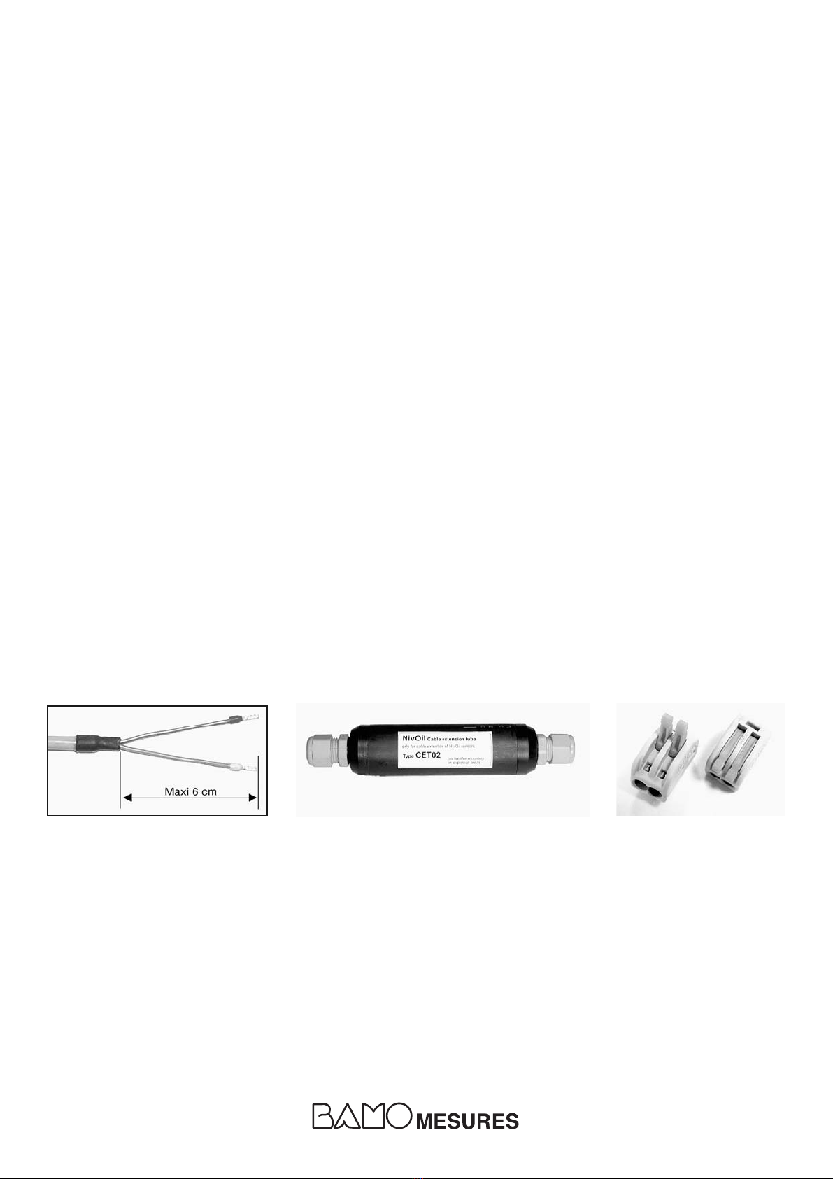
2°) Preparing the cables: Remove the external sheath as on the picture A and fit on a cable ter-
minal ends
Cable extension
The maximal length of an extension is 300 m.
Use the specific cable reference SK-PVC-2x1, ATEX certified.
The easier way to extend the cable accordingly with ATEX rules, is to use the CET02 cable
coupling (Pic.B), reference NivOil-JT, suitable to ATEX zone 0category 1.
The device is delivered with 2 WAGO connectors (Pic. C) for fast coupling.
Cable cross section: 4 mm2as a maximum
Protection: IP 65 (not for a continuous immersion)
The shield must not be connected.
Both ends must be pressed to the limit and pressure cable glands well tightened.
3°) Connect the sensors to the control unit NivOil in accordance with the obligations due to Ex
area, as shown on the drawing.
The measuring loop, as an intrinsic safe circuit, must not be connected to the ground.
Connect the control unit to the main power line.
Pic. C
Pic. B
Pic. A
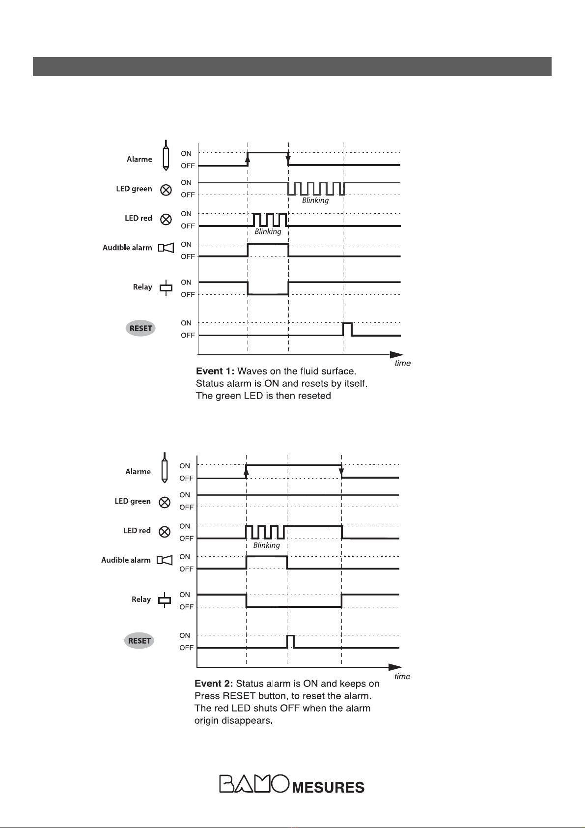
Monitoring modes: continuous monitoring, cyclic monitoring
The energy consumption is adjustable by modifying the duration of each monitoring cycle through
the settings of the DIP switch and the selector. The monitoring frequency is adjustable from 6
minutes to 9 days. Between 2 monitoring, the alarm unit is in sleep mode (monitoring function
in stand by).
When there is not a specific sleep mode period (selector on "0" and DIP 6, 7 and 8 are in ON
position), the alarm unit is continuously monitoring.
When the cyclic monitoring mode is set up, each monitoring cycle begins with a self-diagnostic
of sensors and detection loops in order to begin an alarm routine if necessary.
With 3 sensors connected to the alarm unit, a survey monitoring is completed in about 90 seconds.
The progress of each cycle is shown through a blinking LED (each 4 seconds approx.) on the
front panel.
During the sleep mode period, by pressing the TEST button (1 second approx.) it is possible to
begin directly a monitoring sequence:
lAt this moment, the alarm unit begins its self-diagnostic
lIn case of an alarm condition detected, it begins an alarm routine.
lAfter 90 seconds, the system goes back to the previous cyclic mode.
_________________________

531 M1 02 A 16-07-2010 6
4 START-UP – TESTS
As soon as the alarm unit is powered, it begins a test of its alarming devices (LED and buzzer).
lTest of all sensors connection (short circuit and broken cable of measuring loops).
lDetection of sensor type, if the result is positive, the corresponding LED will light on.
In case of a defect detected, the 3 LED, corresponding to this input, will be flashing.
For a non connected channel, the 3 LED keep OFF.
During the first start-up, the alarm device NivOil memorizes the type of sensor connected
to each chan-nel.
lWhen the TEST mode is activated, an audible signal occurs if everything is correct.
The factory settings are: "without sensors"
lWhen you connect a new sensor on a free channel, the alarm device NivOil will identify and
memorize it as soon as you switch on the power.
If a sensor is removed, the corresponding 3 LED will be flashing (defect alarm).
Proceed to a reset, pressing the RESET button at least 5 seconds to confirm the removal of the
sensor.
lWhen a sensor is removed without a complete RESET, then all the LED will be flashing to alarm
of this error status.
4°) Connect back
the ribbon cable and close
the cabinet

531 M1 02 A 16-07-2010 7
5 ALARM SYNOPTIC DIAGRAMS
Note: To avoid false alarms a 10 seconds delay is factory set up.
For hydrocarbon fluid layer thickness and overfilling sensors (DIP3 = OFF)

531 M1 02 A 16-07-2010 8
The test could be completed with the probe outside the separator and totaly immersed in water.
After the auto diagnostic sequence, the control unit recognized the sludge probe and will:
- Alarming when the probe ends are in the air
Or/and
- When probe ends are inside 1 cm or 2 cm inside sludges (sand, soils etc.)
The alarm synoptic diagrams for the sludge probe are identical to the diagrams for hydro-
carbon fluid layer thickness and overfilling sensors
For sludge probe (DIP3 = OFF)
Repeat alarm function:
The alarm repeat function is disabled
or activated with the DIP switch 2.
When DIP 2 is in position "ON" the
alarm will repeat again 24 hours
after the first event, if the alarm
event is not corrected.

531 M1 02 A 16-07-2010 9
6 ALARM SIGNALS
When the unit starts up (and after the self diagnostic)
When the device is operating during MONITORING MODE
Defect Signal
eAll the green LED are blinking
Short circuit in the measuring loop eAudible alarm is ON
eRelays are OFF
eAll the LED are shut OFF
Measuring loop cable is broken eAudible alarm is shut OFF
eRelays are OFF
eAll the LED are shut OFF
Wrong polarity on sensor wiring eAudible alarm is shut OFF
eRelays are OFF
Sensor status Alarm status Signals
Without defect No alarm Green LED (on corresponding function) eLight on
No reset No alarm All green LED (on corresponding channel) eBlinking + buzzer
defect
Reset defect, but No alarm All green LED (on corresponding channel) eBlinking
not corrected
Without defect No reset alarm Red LED (on corresponding channel eBlinking + buzzer
Green LED (on corresponding function) eLight on
Without defect Reset alarm, but Red LED (on corresponding channel) eLight on
not corrected Green LED (on corresponding function) eLight on
Sensor status Alarm status Signals
Without defect No alarm Green LED (on corresponding function) eBlinking
No reset No alarm All green LED (on corresponding channel) eDoubled blinking
defect
Reset defect, but No alarm All green LED (on corresponding channel) eDoubled blinking
not corrected
Without defect No reset alarm Red LED (on corresponding channel eDoubled blinking
Green LED (on corresponding function) eBlinking
Without defect Reset alarm, but Red LED (on corresponding channel) eBlinking
not corrected Green LED (on corresponding function) eBlinking
When the device is operating during SLEEP MODE

531 M1 02 A 16-07-2010 10
7 AUDIBLE ALARM
To disable the audible alarm use the DIP switch 1 inside the cabinet. Therefore the alarm status is
indicated by the LED (only).
8 TEST MODE
The NivOil alarm device NivOil runs an auto-diagnostic sequence each time you need to test
the system:
lPress the "TEST" button (at least 1 second)
ÂAuto-diagnostic routine begins, LED are blinking (LED test)
ÂThe buzzer is switch ON (Audible alarm test)
ÂCheck out of sensor parameters (test of sensor type, short-circuit, broken cable)
Positive test: Corresponding LED are ON
Negative test: Corresponding green LED are blinking
9 MAINTENANCE
The alarm device and its sensors do not require any maintenance operation in normal operation.
After an alarm occurred, the sensors must be cleaned as the separator is drained.
To clean out a sensor use a wetted rag, with a house cleaning and degreasing liquid.
10 PRECAUTION
Hydrocarbon fluid layer thickness sensor
Thickness detection cannot be performed properly in contact with existing chemical substances
such as emulsifiers and surface active wetting agents (detergent). The sensor must be in contact
only with liquids compatible with polyethylene.
Caution
Disconnect from the main power
Before opening the cabinet

531 M1 02 A 16-07-2010 11
11 TECHNICAL FEATURES
Main power supply: 10...27 V DC
Power consumption: 0.1 W / 12 V DC (3 sensors operating, 1 monitoring per hour)
Housing protection: IP65, according EN 60529
Temperature limits: -20...+60 °C
Sensor inputs: 3 inputs with automatic sensor type detection for hydrocarbon fluids
layer thickness, overfill level, sludge layer level
Monitoring: The alarm device NivOil has an auto-diagnostic of measuring loop.
An alarm signal occurs in case of dysfunction due to a short circuit
or a broken cable.
Display and signals: 1 function signal LED (green) on each channel
1 alarm signal LED (red) on each channel
Built-in audible alarm, disabled by DIP switch configuration
Front panel: 2 push buttons for diagnostic test and alarm clearance
Outputs: 3 relay outputs, 250 V AC / 0.45 A / 10 W, potential free change over
contacts
Ex protection class: I 3 (1) G Ex nAC [ia Ga] IIB / IIA T4 Gc
ATEX certificate: BVS 10 ATEX E 011
CE Marks: According to EC directives,
Low Voltage Guidelines: RL 2006/95/EG & RL93/68/EWG,
EMV Guidelines: RL 89/336/EWG (EN 61326)
ATEX: RL 94/9/EG (ATEX 95)
EN 60079-0 (General requirements)
EN 60079-11 (Intrinsic safety)
EN 60079-26 (Group II; category 1G)
NivOil CU/12 – Alarm device
(1) The alarm device NivOil may be installed in zone 2.
(2) For intrinsic safety parameters [Uo, Io, Poand Co, Lo],
see details in the ATEX certificate.

531 M1 02 A 16-07-2010 12
Sensor type: Capacitive, high frequency
Wetted parts: Antistatic PE stem; Stainless steel end probe
Cable: Elastomer resistant to oils and hydrocarbon fluids,
blue colour; wires 2x1mm2, connections to the
alarm device NivOil on screw connectors;
10 m long cable (max length is 300 m)
Protection: IP68 acc. EN 60529
Temperature limits: -20...+60°C
Ex protection class: II 1 G Ex ia IIB T4 (Intrinsic safety)
ATEX certificate: BVS 07 ATEX E 091X
Sensor type: Ultrasonic detector type
Wetted parts: PVC
Cable: Elastomer resistant to oils and hydrocarbon fluids,
blue colour; wires 2x1mm2, connections to the
alarm device NivOil on screw connectors;
10 m long cable (max length is 300 m)
Protection: IP68 acc. EN 60529
Temperature limits: -20...+60°C
Ex protection class: II 1 G Ex ia IIB T4 (Intrinsic safety)
ATEX certificate: BVS 09 ATEX E 021X
Sensor type: Ultrasonic detection type
Wetted parts: PVC
Cable: Elastomer resistant to oils and hydrocarbon fluids,
blue colour; wires 2x1mm2, connections to the
alarm device NivOil on screw connectors;
10 m long cable (max length is 300 m)
Protection: IP68 acc. EN 60529
Temperature limits: -20...+60°C
Ex protection class: II 1 G Ex ia IIB T4 (Intrinsic safety)
ATEX certificate: BVS 09 ATEX E 021X
NivOil-HPS/10 – Overfilling sensor
(Only for use with an alarm device NivOil)
NivOil-SP/10 – Sludge layer sensor
(Only for use with an alarm device NivOil)
NivOil-OP/10 – Hydrocarbon fluid layer thickness sensor
(Only for use with an alarm device NivOil)
(1) These sensors may be installed in zone 0
(2) For intrinsic safety parameters [Ui, Ii, Piand Ci, Li],
see the details in the ATEX certificate for each sensor.
Other manuals for NivOil
1
Table of contents
Other Bamo Security System manuals
Popular Security System manuals by other brands

Extel
Extel WESV 82500 Installation and user guide

Neat
Neat D-POS II user manual

Scientific Atlanta
Scientific Atlanta Explorer 8300 Getting started

Hiltron
Hiltron XR400GSM INSTALLATION GUIDE AND USE

Se-Kure Controls
Se-Kure Controls ME Jr. plus 2 SK-800MEI Series installation instructions

Dakota Alert
Dakota Alert AD-01 Kit owner's manual