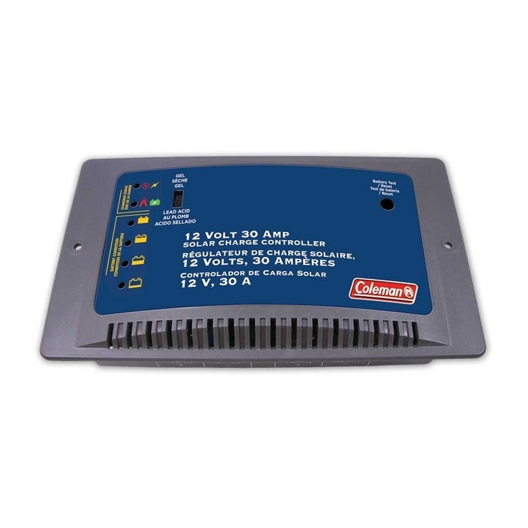
The AVC1 is an external voltage regulator/recƟfier
designed for use with single-phase permanent-magnet
alternators up to 20A in size. Over-voltage protecƟon,
Charging System-fault and Low-voltage warning
output, and field-adjustable charging voltage are
integrated into the AVC1 control package.
Case - Ground VOLT ADJ - Voltage RegulaƟon Adjustment
CONFIG - LV Warning ConfiguraƟon
Terminals 1 & 2 - AC Input
Terminal 5 - Warning Output
Terminals 3 & 4 - DC Output (+) Terminal 6 - Control Input
♦ For DucaƟretrofit, AVC1 may be installed with no
wiring changes. Otherwise, refer to Diagrams 1 & 2
(reverse) for suggested wiring configuraƟons.
♦ Disconnect ship’s baƩery, NegaƟve (-) post first.
♦ Mount the AVC1 & filter capacitor (if used) on the
firewall or selected locaƟon, terminal strip DOWN.
♦ Wire the AC input. Connect Terminals 1 & 2 to the
two AC leads from the alternator/dynamo, using
the supplied wire terminals and heatshrink, if
needed. Note: there is no polarity in these wires.
♦ Wire the DC power (+) output. Connect Terminals
3 & 4 to the posiƟve (+) post on the filter capacitor
(if used) and the aircraŌbus at the output current
limiter(s) or panel circuit breaker.
Download the full AVC1 Technical Manual
for more detailed installation guidance:
www.BandC.com/AVC1install
MONDAY-FRIDAY 9:00 - 4:30 CENTRAL
The AVC1 provides warning output for Charging-
System Fault (CSF) and Low-Voltage (LV) condiƟons.
LV warning is user-selected to trigger at one of three
voltage thresholds. It may be disabled, also, if desired.
LV warning opƟons may be selected by
posiƟoning two small
DIP switches behind
the machine screw
cap labeled “CONFIG”
on the side of the
AVC1 enclosure. The
factory preset is 12.7v.
LV Warning Switch 1 Switch 2
Disabled DOWN DOWN
12.7v DOWN UP
13.0v UP DOWN
13.3v UP UP
LV warning-select DIP switches
♦ Wire the Warning Output. Connect Terminal 5 to
appropriate EFIS input or the panel indicator light.
♦ Wire the Control Circuit. Connect Terminal 6 to the
baƩery/alternator master switch.
♦ Wire the Ground circuit. Using 12AWG M22759/16
wire, connect one of the two mounƟng flanges on
the AVC1 to the aircraŌfirewall Ground, Grounding
block, or baƩery NegaƟve (-) post.
♦ Connect ship’s baƩery, PosiƟve (+) post first.
♦ Test the installaƟon. Perform a normal engine start.
Charging should be indicated at 13.8v to 14.4v. LV
indicaƟon may occur iniƟally, but should cease as
bus voltage rises above the selected warning
threshold.


