B&K 4416 User manual
Bruel &Kjmr
r
--------------------------
~
037
-
26
1
4416
Response Test
Unit
valid from serial
no
.
575443
-.,

BRUEL & KJA:R
Ncerum -
Denmark
Consisting
of:
Service
In
struction
S
Imphfled
Diagram
Adjustment
Procedure
ZS
0298
Remote
Control
ZT
0294
Amplifier
/
Power
Supply
ZT
0295
Input
Filter
Circuit
Diagram
with
Parts
List
/
Cabinet
Parts
4 .
76
037
261
Service
Instruction
4416
4416
Response Test
Unit
Page
0- 1
0- 2
1 1
1- 2
1- 3
1- 4
2
1
2
valid
from
serial
no
.
575443
Dat
e
4.
76
4.76
4
.7
6
4
.76
476
4 .
76
.
76
.
76
.
76
.
76
1.
76
TroubJe
Shooting
If
any
faults
should
occur
please
check
the
instrumenl
according
10
Ihe
Adjustment
Procedure
.
When
a
fault
has
been
traced
and
corrected
,
the
voltages
and
adjuslments
influenced
by
the
correction
must
be
rechecked
. The
comp
let
e
instrument
shou
ld
then
be tes
ted
to
make
sure
that
all basic
functions
are
operative
.
The
tolerances
given
in
thes
e
notes
are
intended
for
use
as gUide
for
ad-
justments
.
Before
correcting
any
apparent
deviation
make
sure
that
th
e
measuring
instrument
has
tolerances
small
enough
not
to
affect
th
e
measurernenl.
Modifications
Due
to
the
constant
technical
progress
the
instrument
will
be
modified
from
time
to
time
in
order
to
provide
continously
improved
performance
.
For
this
reason
there
may
be
smal
l
differencies
between
the
instrument
and
the
Service
Instru
ction.
However.
the
local
Representative
Service
is
in
possession
of
all
informa-
tion
regarding
the
modifications
that
have
been
made
.
Spare
Parts
Please
state
type
and
serial
number
of
the
instrument
when
ordering
spare
parts
.
0-1

~
N
-!:>
-..J
(j)
Amplifier
Preamp
.
Zi47kIl
~
Input
10
mY
I
{/
R
10mY
Boost
75}JS
IEC
To
po
Input
100
mY
p
Generator
ILin
'r
I
5 V
RE=:3O---
L+R
~
Chop
~
I I 5 V
I
R
Rumble A -0"0 f T
~!
s'
R
5V
Rumble 8 ..,..-0
ItT
I
-i
s
Out
R
100 mY
5V
~
5V
1Hz
Choppor
to V
11
_ t
oV13
--
-to V 12
to
Q 8, 9
Y11
to
V
23
Rumble
A B
LP
315
Hz BP
315
Hz
U:~m
.
f '
J"'
Cf)
3
~
3
CO
a.
o
'"
<C
...,
'"
3
-!:>
-!:>
(j)
BRUEL
&
KJ~R
Nrerum
-
Denmark
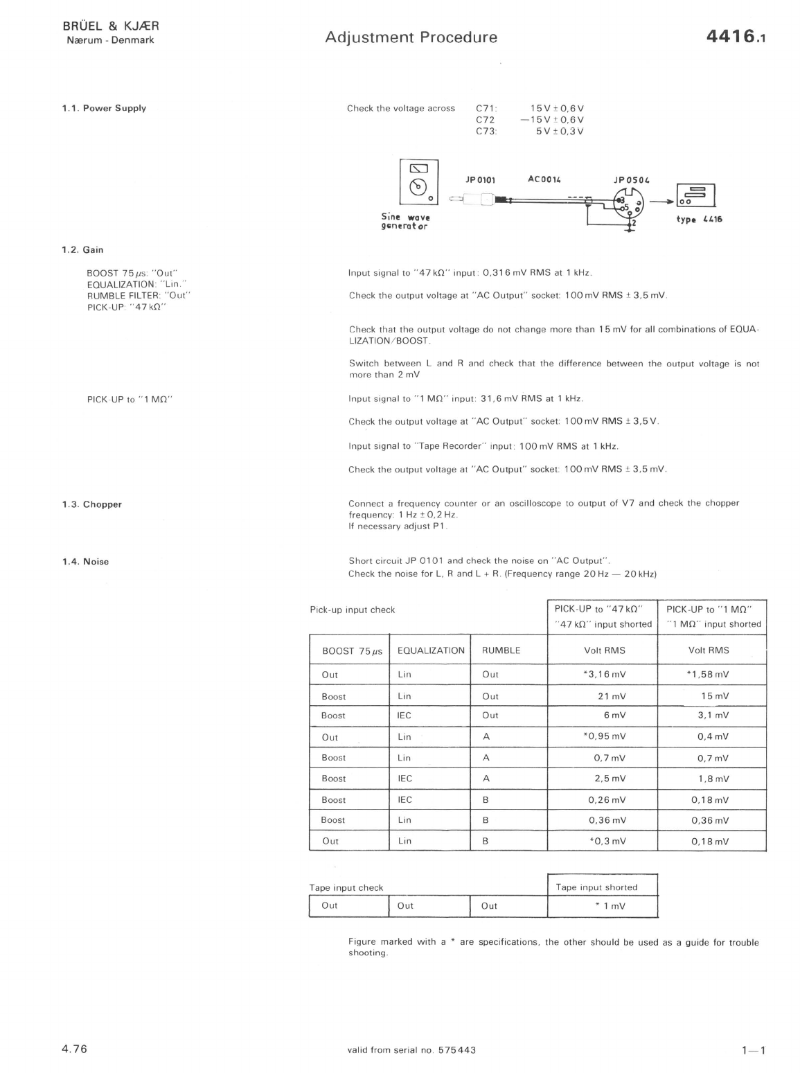
1.1.
Power
Supply
1.2.
Gain
BOOST 7511S
"Out"
EQUALIZATION
"Lin
."
RUMBLE FILTER:
"Out"
PICK-UP "
47kO
"
PI
CK
-UP to " I
MO
"
1.3.
Chopper
1.4.
Noise
4.76
Adjustment
Procedure
4416.1
Check
the
voltage across
C7
1:
C72
C73
JPOIOI
15V
±
0,6V
-
15V
±
0.6V
5V±0.3V
ACOOI'
c
=L
=
"-Ia:ll======~i:::::::;
5"
-
~
__
~JP050'
~
I1
°
type
4416
Sine
waVe
gQnorot
or
Input
signal to
"47
kO"
input
0.
316
mV
RMS at 1 kHz .
Check
the
output
voltage
at
"AC
Output"
socke
t:
1
00
mV
RMS ±
3.5
mV
.
Check
that
the
output
voltage
do
not
ch
ange
more
than
15
mV
for
all
combinations
of
EQUA-
LIZATION/BOOST.
Switc
h
between
Land
R and check
that
the
difference
between
the
outp
ut
voltage is
not
more than 2
mV
I
nput
signal
to " I
MO
"
inpu
t:
31
.6
mV
RMS at 1 kHz.
Check
the
output
voltage at "AC
Output
" socket: 1
00
mV
RMS ± 3,5 V.
Input
signal to
"Tape
Recorder"
input
·
100
mV
RMS at 1 kHz.
Check
the
output
voltage at
"AC
Output"
socket: 1
00
mV
RMS ± 3.5
mV
.
Connect a
fr
e
qu
ency cou
nt
er
or
an oscilloscope to
outp
ut
of
V7
and check
the
chopper
fr
equency:
1 Hz ±
0.2
H
z.
If necessary
ad
ju
st
PI
Short
circu
it
JP
0101
a
nd
check
the
noise
on
"AC
Output"
Check
th
e noise for L.
Rand
L + R. (Frequency range
20
Hz -
20
kH
z)
Pick-
up
input
check PICK -UP to "
47kO
" PICK-UP to " I
MO
"
"
47
kO"
input
shorted
" I
MO
"
input
s
hort
ed
BOOST
7511S
EQUALIZATION RUMBLE
Vo
lt
RMS
Volt
RMS
Out
Lin
Out
*3.16mV
*1 ,
5BmV
Bo
ost
Lin
Out
21
mV
15mV
Boost
IE
C
Out
6mV
3.1 mV
Out
Lin A *0
.95
mV
O.4mV
Boost Lin A
O,7mV
0.7mV
Bo
ost
IE
C A
2.5mV
1
.8
mV
Boost
IEC
B
0.26
mV
0.
18mV
Boost Lin B 0,
36
mV
0,
36
mV
Out
Lin
B *0 ,3
mV
0,
18mV
Tape
input
check Tape
input
sho
rted
l
Out
l
Out
l
Out
* 1
mV
Figure
marked
with
a * are
specifications
, the
other
s
hould
be used as a
guide
for
troubl
e
s
ho
o
ting
.
valid
fr
om serial
no
.
575443
1- 1

Adjustment
Procedure
4416
.1
1.5 .
Distortion
1.6 .
Frequency
Res
pons
e
• Bruel & Kim,
Check
the
dis
tortion
for
L.
Rand
L + R according
to
the
scheme
belove.
The
distortion
sho
uld
be
measured
w
ith
an
output
voltage
of
1 V
RMS
.
Tape
input
IEC/BOOST
Pick-
up
input
LIN
/BOOST
Remote
Control
1
AQ
0038
2010
2307
UB
OOLl
Qlnput
9
r BFO I
Output
20Hz
-
20
kHz
5 Hz -
50
kHz
5 Hz -
50
kHz
r LL16 1
'lor
Zi
L7k1l.
<
70dB
<
60dB
<
50dB
/f
rom
"AC
Output
"
to
AC
voltme
ter
(f
.
inst
.2L 27)
To check
it
em
1
.6
an
d 1.7 a Level R
ecorder
and a
Sine
Wave
generator
(
fr
equ
ency
range
2 Hz -
200
kHz) is
necessary
.
The w
ritin
g
width
of the Level
Recorder
is
100
mm.
Bruel & Kim, Bruel & Kimr
00000000000000
0000
000
00000000000
00000000000000000
la-rueI& Kjrer Potentiomete,
Range
:
~dB
Rectifier:
RMS
lower
lim
.
Freq.:~Hz
Wr
. Speed:
-1Lmm
/sec.Paper Speed
:...L
mm
/sec
1- 2
Copenhagen
50
25
1075
1:
Lin
...
dBdB
2:
Lin
+ Boost, 75
J.l.S
dBdB
3: IEC 2+
4020
4: I
EC
+ Boost, 75
J.l.S
Ta
60
Measuring Obi
.:
3 &4-
I-
:,
3015
1-
.
64!
~onse
-
curves
...Q!...ly~
~
~
1 &2 1 &4
4416
20
10
430
3
lOrs
215
Rec.
No
.:
y100
kHz
Date 27·6·75
Sign.: JAH oLa
10
20
Hz
50
100
200 500
1000
2000 5000
10000
200a.-~
00
A B C
lin
. 0
QP
1124
Multiply
Frequency Scale by Zero
level
:
1612
/
2112
A B C
750634
RUMB
LE
FILTER: "
Out
"
Knob
se
tting
f
or
Type
2307
LOWER
LIMIT
FREQ.. "
10H
z"
WRITING SPEED: "
16
mm
"
PAPER SPEED: " 1
mm"
Set
the f
reque
ncy
to
10H
z in 2 Hz - 2 kHz log
frequency
range.
Inp
ut
volt
age
to
"
47
kO"
input
·
0,3
16
mV
RMS.
Start
th
e Level R
eco
rder
and
l
et
it
run
until
approxima
tely
1 kHz.
Stop
the
Level R
ecor
der,
change
the
frequency
r
ange
of
the
generator
to
200
Hz -
200
kHz
and
set
the
fr
e
quency
pointer
to
the
frequ
ency
where
it
was
stopped
.
Start
th
e L
eve
l R
eco
rder
and
l
et
it
run
o
ut
the
'
rest
of
the
chart.
Thi
s
chec
k
sho
uld
be
don
e f
or
L, R, L + R
and
for
both
47
kO/ l
MO
input
s.
4.76

Adjustment
Procedure
4416
.1
1.7 .
Rumble
Filter
BrGel &
Kjmr
-Measuri
ng
Object:
BrGel &
Kjmr
OOOOOOOODDDODOOODDOOOOOOOOOOOOOOOOOOOOOOOOOOOOOOO[
~B
Recording
No
.: Sign
.:
Date
: Potentiometer: Zero Level: 0
ABC
lin.
40
Rumble
A
30
10
o
2 Z 0
IU
OP
1143
Pot
. Range,
EQUALIZATION: "
Lin
."
CHANNEL SELECTOR:
"L
I R"
RUMBLE FILTER:
"Out
"
RUMBLE FILTER
to
"A"
RUMBLE FILTER to
"8
"
1.8.
Max.
Output
Voltage
EQUALIZATION:
"Lin"
RUMBLE FILTER:
"O
ut
"
1.9
.
Cross
talk
4.
76
EQUALIZING:
"Lin
."
CHANNEL SELECTOR: "
R"
PICK-UP"
47
kO"
PICK-UP to " 1
MO
"
o
50 dB
± 1 dB
Rumble
B
50
100
200
500
2
1000
2000
5000
'-10000
20000
50000
100000
3 mm/
sec
.
Rectifier
.:
RMS
lower
lim
.
Freq.:
Hz Writing Speed:
25
mm
/sec.
Paper Speed:
Adjust
the
input
voltage
to
exactly
1 V RMS at
315Hz
on
"AC
Output"
.
Output
voltage: 1 V RMS ±
20
mV
.
Output
voltage: 1 V RMS ±
20
mV
.
Record
the
frequency
response
for
RUMBLE A and RUMBLE B
filters
.
Connect
an osc
ill
oscope to
"AC
Output"
socket and check
that
the
output
signal is
not
dis-
tored
for
an
input
voltage
of
:
23
mV
RMS
to
"47
kO"
input
2,
3V
RMS
to " 1
MO"
input
Check max.
output
voltage for L, R, L + R and
for
both
47
kO
and 1
MO
inputs
.
Connect
the
input
signal
to
pin 3 and short
circuit
pin 5 to
gro
und
on
47
kO
input
Adjust
the
input
signal
to
3,16
V
RMS
at 1 kHz on "AC o
utput
"
Switch
C
HANNEL
SELECTOR to
"L"
and check the cross
talk
acording to
the
scheme
below
.
Inpu
t
Pi
ck-
up
Tape
fr
equency
47
kO 1
MO
1 kHz
-65
dB
-65
dB
-65dB
20
kH
z
-45d
B
-40d
B
-45
dB
50kHz
--
35
dB
-30d
B
-3
5 dB
Change
the
input
to
channe
l
"L"
and check the cross
talking.
Change
the
input
S
ignal
to " 1
MO
"
input
and check
the
cross
talk
as described
for
" 47
kO
"
input
.
Change
the
input
s
ignal
to
"Tape"
input
and
check
the
cross
talk
as described
for
" 47
kO"input
valid
from
se
rial
no
.
575443
1- 3

Adjustment
Procedure
4416.1
1.
10
.
Synchrostarter
1- 4
Le¥l!l
Recorder
start
:
OV
EQUALIZING "Lin
."
CHANNEL SELECTOR: " L , R"
RUMBLE FILT
ER
:
"Ou
t"
PICK-UP: "
47kO
"
SYNCHROSTART:
"A
ut."
Level Recorder
type 2307 I
I
I
~~~~~;
.-----
--
,
I 0 : \
~--_1""H>
I "
I
io
I Remote Control
I
I
I
I
I
I
--
-~
Level Recorder
type 2305
G
Remote
Control
Automatic
Stop
Clutch
Remote
Control
Coble
AQ 003e
type
4416
30V
from
Level
1IecQ-~
~
,
6,
I
15V
a
JOZ
C
305
Connect
" R
emo
te
Control"
on Type
44
16 to "Remote
Control
" on the Level Recorder.
Ad
ju
st
the
input
signal
fa r 1
00
mV
RMS at
950
Hz on "AC
Output
".
Switch
PAPER DRI
VE
FUNCTION on Type
2307
to
"
Continue
F
".
Press "BFO
Stop"
on Type
2010
and check
th
at
the
Level R
ecorder
sta
rt
s,
If
the
Level Recorder does
not
start
adjust
L301
(on
ZS
0298)
until
the
relay
0301
will
be
energized and repeat the check.
Change t
he
input
frequency
to
1050
Hz and check
again
the
start
function
.
If the Level R
ecorder
does
not
s
tart
adjust
L
30
1
until
the
relay
030
1
will
be energized a
nd
repeat
the
star
t
function
.
Change
the
input
frequen
cy
to
700
Hz and let the Level Recorder
run
until
a
utomatic
stop.
Increase
the
input
fr
e
quency
sl
ow
ly and check t
hat
the
relay
will
be energized
between
800
Hz and
950
Hz and
the
Level Recorder
will
be
started
between
1
050
Hz and
1250
Hz
.
Repeat the
adjustment
of L
30
1
until
this
is
fullfill
ed.
4.
76
BRUEL & KJ.tER
Nrerum -
Denmark
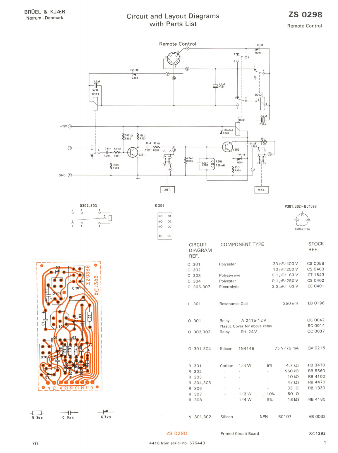
Circuit
and
Layout
Diagrams
with
Parts
List
Remote
Control
lN4148
Q)02
ZS
0298
Remote
Control
lN41411
+lSV
lO)----
--f,-----
T--T---------------
---1~
-
-l
-c:J-
R
3xx
.
76
I
I
I
I
I
4,7kO
@>-----+.bi4
J
]nF
~1-D1+--'.>N30""
____
-I-r
1
0302,303
1 2
0 0
[;
0
1 6
-1~
c
3xx
3
~
-<>
,
18kO
Rloa
~
Q3xx
1
I
~
0301
' 0 01
, 0
02
60
03
' 0
01
CIRCUIT
DIAGRAM
REF
.
C 301
C
302
C
303
C
304
C
305
-
307
L 301
0 301
0
302
,
303
Q 301 -
304
R 301
R
302
R
303
R
304
,
305
R
306
R
307
R
308
V 301 ,
302
ZS
0298
4416
from
serial no.
575443
330
AJDS
V301.302 -
BC
107B
B
,0,
Botlom
...
i,w
COMPONENT TYPE STOCK
REF.
Polyester
33
nF
/
400V
CS
0058
10
nF1250
V
CS
0403
Polystyrene 0 ,1
/JF
1
63
V
CT
1543
Polyester 0,1 /JF1250 V
CS
0402
Electrolytic
2,2/JF
/
63V
CE
0401
Re
sonance Coil
250
mH
LB
0196
Relay A
2415-12V
OC
0042
Plastic Cover for above relay
SC
0014
Relay
RH
-
24V
OC
0037
Silicon
lN4148
75
V175
mA
QV
0216
Carbon 1/
4W
5%
4,7
kO
RB
3470
560
kO
RB
5560
10
kO
RB
4100
47
kO
RB
4470
33
0
RB
1330
1/
3W
10
%
50
0
1/
4W
5%
18
kO
RB
4180
Silicon
NPN
BC107
VB
0032
Printed
Circuit
Board XC
1292

BROEL
&
KJA:R
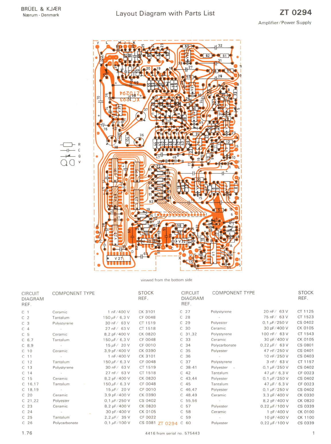
Ncerum -Denmark Layout Diagram
with
Parts List ZT
0294
Ampl
ifier
/
Power
Supply
-c:J-
R
--I~
c
~a
00
v
I.
I
I.
I
1_
________
J
_____
-I
viewed
from
the
bottom
side
CIRCUIT
COMPONENT
TYPE STOCK CIRCUIT
COMPONENT
TYPE STOCK
DIAGRAM
REF.
DIAGRAM
REF
.
REF
. REF.
C 1 Ceramic 1
nF
/
400
V
CK
3101
C
27
Polystyrene
20
nF
I
63
V
CT
112
5
C 2
Tantalum
150IJ
F/
6,3V
CF
0048
C
28
75
nF
I
63
V
CT
1523
C 3 Polystyrene
30
nF
I
63
V
CT
1519
C
29
Polyester
0,1
IJF
/
250
V
CS
0402
C 4
27
nF
I
63
V
CT
1518
C
30
Ceramic
30
pF
/
400
V
CK
0105
C 5 Ceramic 8,2
pF
/
400
V
CK
0820
C
31
,
32
Polystyrene
100
nF
I
63
V
CT
1543
C 6,7
Tantalum
150IJ
F/
6,3V
CF
0048
C
33
Ceramic
30
pF
/
400
V
CK
0 1
05
C 8,9
15IJF
/
20V
CF
0010
C
34
Polycarbonate
O,22IJF
1
63
V
CS
0801
C
10
Ceramic
3,9
pF
/
400
V
CK
0390
C
35
Polyester
47
nF/
250
V
CS
0401
C
11
1
nF
/
400
V
CK
3101
C
36
10
nF
/
250
V
CS
0403
C
12
Tantalum
150IJF
/
6,3V
CF
0048
C
37
Polystyrene 3
nF
I
63
V CT
1157
C
13
Polystyrene
30
nFI
63
V
CT
1519
C
38-41
Polyester 0,1
IJF
/
250
V
CS
0402
C
14
27
nFI
63
V
CT
1518
C
42
Tantalum
47
IJF
I
6,3
V
CF
0023
C
15
Ceramic 8,2
pF
/
400
V
CK
0820
C
43.44
Polyester 0,1
IJF
/
250
V
CS
0402
C
16
,
17
Tantalum
150IJ
F/ 6,
3V
CF
0048
C
45
Tantalum
47
IJF
I 6,3 V
CF
0023
C
18
,
19
15IJF
I
20V
CF0010
C
46.47
Polyester 0,1
IJF
/
250
V
CS
0402
C
20
Ceramic 3,9
pF
/
400
V
CK
0390
C
48.49
Ceramic 3,3
pF
/
400
V
CK
0330
C
21
,
22
Polyester 0,1
IJF
/
250
V
CS
0402
C
55
,
56
8,2
pF
/
400
V
CK
0820
C
23
Ceramic 8,2
pF
/
400
V
CK
0820
C
57
Polyester O,
22IJ
F/ 1
00
V
CS
0339
C
24
30
pF
/
400
V
CK
0105
C
58
Ceramic 1
pF
/
400
V
CK
0100
C
25
Tantalum
2,
2IJF
1
35
V
CF
0022
C
59
10
pF
/
400
V
CK
110
0
C
26
Polycarbonate O,
lIJF
/
100V
CS038
1
ZT0294
C
60
Polyester
O,22IJF
/ 1
00
V
CS
0339
1.
76
4416
from
serial no.
575443

ZT
0294
Layout Diagram
with
Parts List
CIRCUIT
DIAGRAM
REF
.
C
61
C
62
C
63
,
64
C
65
C
68
,
69
C
70
C
71
-
73
C
74
-
77
C
78
P 1
o 1-
20
o
28
-
30
R
R 2
R 3
R 4
R 5
R 6
R 7
R 8
R 9
R
10
R
11
.12
R
13
R
14
R
15
R
16
R
17
R
18
R
19
R
20
R 21
R
22
R
23
R
24
,25
R
26
R
27
.28
R
29
R
30
R
31
R 32
R
33
R
34
R
35
-39
R
40
R
41
R
42
R
43
R
44
R
45
R
46
R
47
R
48
R 49
2
COMPONENT TYPE
Ceramic
Polyester
Ceramic
Electrolytic
Tantalum
Ceramic
Electrolytic
Cermet
Silicon 1
N4148
1N4004
Metal
Carbon
Metal
Carbon
Metal
Carbon
Me
ta
l
Carbon
Metal
Carbon
Metal
Carbon
Met
al
Carbon
Metal
Carbon
Metal
Ca
rb
on
1/
4W
1
pF
/
400
V
10
pF
/
400
V
0,1 IlF/
250
V
30
pF
/
400
V
100llF
I
40
V
470llF
I
40V
151lFI
20V
47
nF
I
30V
221lF
I
40V
1%
5%
1%
5%
1%
5%
1%
5%
1%
5%
1%
5%
1%
5%
1%
5%
1%
1%
5%
22
kO
75
V175
mA
400
V/ 1 A
61
.9
kO
100
0
2
kO
47
kO
3,32
kO
9,
76
kO
115
kO
12
,7
kO
10
kO
4,75
kO
47
,5
kO
47
kO
61.9
kO
100
0
2
kO
47
kO
3,;32
kO
9.
76
kO
115
kO
12,7
kO
10
kO
4,75
kO
47
,5
kO
47
kO
49
,9
kO
24
,9
kO
22
kO
330
kO
10
kO
100
kO
15
kO
100
kO
39
kO
15
kO
39
kO
15
kO
39
kO
15
kO
39
kO
15
kO
22
kO
15
kO
STOCK
REF
.
CK
0100
CK
1100
CS
0402
CK
0105
CE
0443
CE
0417
CF
0010
CK
4470
CE
0428
PG
3221
OV0216
OV
0237
RF
4619
RB
2100
RF
3200
RB
4470
RF
3332
RF
3976
RF
5115
RF
4127
RB
4100
RF
3475
RF
4475
RB
4470
RF
4619
RB
2100
RF
3200
RB
4470
RF
3332
RF
3976
RF
5115
RF
4127
RB
4100
RF
3475
RF
4475
RB
4470
RF
4499
RF
4249
RB
4220
RB
5330
RB
4100
RB
5100
RB
4150
RB
5100
RB
4390
RB
4150
RB
4390
RB
4150
RB
4390
RB
4150
RB
4390
RB
4150
RB
4220
RB
4 150
CIRCUIT
DIAGRAM
REF.
R
50
R
51
R
52
R 53
R
54
,
55
R
56
R
57
R
58
R
59
R
60
R
61
R
62
R
63-65
R
66
.
67
R
69
R
70
R
71
R
72
-
75
R
76
R
81
-
87
R
90
R
91
,
92
R
95
,
96
R
97
R
98
R
99
.
100
R 101
R
102
R
103
R
104
,
05
V
V 2-7
V 8
V 9-
13
V
14
-
20
V
21
,
22
V
23
-
25
V
26
V
27
V
28
V
29
V
30
V
31
V
32
-3
4
V
35
V
36
V
37
V 38
COMPONENT TYPE
Metal
Carbon
Metal
Carbon
Metal
Carbon
Metal
Carbon
1/
4W
1%
5%
1%
5%
1%
5%
1%
5%
Metal 1%
Carbon
Metal
Carbon
2 x Op.
Amp
.
Op
.
Amp
.
Silicon
PNP
FET
N
Silicon
PNP
Op.
Amp
.
FET
N
4 x 2 Input NAND
S-R Flip-Flop
2 x 4 Input NAND
6 x
IN
V
4 x 2 Input NAND
S-R Flip-Flop
Op.
Amp
.
±
15
V Regulator
Sili
co
n
PNP
5%
1%
5%
NP
N
5 V R
eg
ulator
Printed Circuit Board
Heatsink
8 pin-Socket for dual-in-
lin
e
14
pin-Socket for dual-in-
lin
e
16 pin S
oc
ket for
ci
rcuit b
oa
rd
82
,5
kO
15
kO
82
,5
kO
15
kO
39
kO
45
,3
kO
17,4
kO
5,
62
kO
27
kO
11
kO
3,
83
kO
12
kO
100
kO
4,7
kO
68
kO
47
kO
10
kO
1
kO
100
0
1
kO
390
0
1
kO
499
kO
316
kO
330
kO
499
kO
316
kO
330
kO
220
kO
150
0
739
301
BC
177
NF510
BC177
301
NF510
7400
74279
7420
7416
7400
74279
301
4195
40406
404
07
78M
05
STOCK
REF
.
RF
4825
RB
4150
RF
4825
R8
4150
R84390
RF
4453
RF
4174
RF
3562
RB
4270
RF
4110
RF
3383
RB
4120
R85100
RB
3470
RB
4680
RB
4470
RB
4100
RB
3100
RB2100
RB
3100
RB
2390
RB
3100
RF
5499
RF
5316
RB
5330
RF
5499
RF
5316
RB
5330
RB
5220
RB
2150
VE
0079
VE
0044
VB
0071
VB
1021
VB
0071
VE
0044
VB
1021
VD
0002
VD
0073
VD
0007
VD
0051
VD
0002
VD
0073
VE
0044
VE
0068
VB
0053
VB
0054
VE
00
69
XC
1293
DT
0036
JJ
0804
JJ
1408
JJ
16
24
1.
76

BRUEL
&
KJ...:ER
Nrerum -Denmark
-c::::J-R2
xx
-+-C2""
CIRCUIT COMPONENT TYPE
DIAGRAM
REF.
C
201
Polystyrene
C
202
Ceramic
C
203
C
204
Polystyrene
C
205
C
206
Ceramic
C
207
Polys
tyr
ene
C
208
Ceramic
C
209
C
210
Polys
tyr
ene
C 211
C 212 Ceramic
C
213
-215
Push
Button
Selector
1.
76
Layout Diagram
with
Parts List
o
------------------
·
---------
----
--
--
-
~
~r
• I
cr
I>
r
c 011>"
.0.0
II) II)
I
I
0-
I
, ,
-l
U I
: : I : I
V1
X I
e-
-- -
-,
;oO~l-
r~~~
T
-,
j;r
r;;:~~
rT~~~
r-
---
-a
Vie
wed
from
the
top side
STOCK CIRCUIT
COM
PONENT TYPE
REF
.
DIAGRAM
REF.
l ,
6nF
/
500V
CT
1103
R
201
Metal
1/
4W
33
pF/
400
V
CK
1330
R
202
150
pF
/
400
V
CK
2151
R
203
11
nF
I
63
V
CT
1551
R
204
Carbon
130pF
/ l
00V
CT
1138
R
205
Met
al
150
pF
/
400
V
CK
2152
R
206
1,6 nF/
500
V
CT
1103
R
207
33
pF
/
400
V
CK
1330
R
208
150
pF
/
400
V
CK
2151
R
209
11
nFI
63
V
CT
1551
R
210
130
pF
/ l
00
V
CT
1138
R
211
Ca
rbon
150
pF
/
400
V
CK
2151
R
212
Metal
47nF
/
30V
CK
4470
R
213
R
214
OJ
0056
V
201
-
204
Op.
Amp
.
Printed Circ
uit
Board
ZT
0295
4416
from
serial no.
575443
ZT
0295
Input
Filter
STOCK
REF
.
1%
47
,5
kO
RF
4475
2,21
kO
RF
3221
4,
99
kO
RF
3499
5% 4,7
kO
RB
3470
1%
953
0
RF
2953
9,
53
kO
RF
39
53
475
0
RF
2475
47
,5
kO
RF
4475
2,21
kO
RF
3221
4,
99
kO
RF
3499
5% 4,7
kO
RB
3470
1%
953
0
RF
2953
9,
53
kO
RF
3953
475
0
RF
24
75
301
VE
0044
XC
1294


BRUEL & KJA:R
Nrerum -
Denmark
Circuit Diagram
with
Parts List
1
1
1
1
1
1
1
I
1
1
1
1
1 /
I,
QA
0048
Q
21
-
27
R
77
-
80
R
88
,
89
1.76
LED
RL209
Carbon 1/
4W
Printed
Circuit
Board
5%
3900
3900
Print
ed
Circuit
Board
with
components
16-pole
Fl
exible I
nterconnector
BNC Socket
7-
pin
DIN
Socket
Banana Socket
Mains
Socket
Stand
-
Off
Main
s
Voltage
Selector
Fu
se, s
low
220
V
Fuse,
slow
110
V
Mains
Transformer
QV
4001
RB
2390
RB
2390
XC
1295
OZ
0011
AR
1010
JJ
0121
JJ
0709
JT
6204
OA
0037
XL
0163
JS
0001
VF
0012
VF
0026
TN
0103
YV
1325
~
~e
Mains
Switch
Cover
for
above
switch
"Pick
up"
Selector
5-
pin
DIN
Socket
Circuit
Board
with
components
Remote
Control
Amplifier
/
Pow
er
Supply
Input
Filter
GV
0673
valid
from
serial
no
.
575443
4416.2
!
@
NN
0014
DO
0088
NN
0040
JJ
0501
ZS
0098
ZT
0294
ZT
0295
2 - 1

47kO
V27,31- SN
74279
nv
"
"'
U
l
.1t
Preamplifiers
B,2pF
C!iS
61,9kO
l.ft
1 0
+15V
O,luF
1'"
0
J..
O,
I,uF
Tezz
~-15V
a,22,uf
2
x499kn
C51
'95
'96
B,2pF
C56
Pick-up
I pf
C58
V32
IpF
RI
13
loon
"
l
OOn
'15
J16kO
'"
1
r--
--,
V26
-3
0 SN
7400
V29-
SN
741
6
V28-SN
7420
0
:
'
V"
. "
GNO
I
C61 JI6 kO
2x49HO
R99
~10
0
V1-)JA739
0'''
·
'0''
Ouip -
lilu
A I Dulp .
lau
B
i"p
-
l,!!
A:
11
In
p. l B
Nu
"
Inverti
ng I Inp .
"9
Invelling
I
Non
Inverling
- v ' I
.verllng
Top
vi"w
RI
OI
V2-7,21,22,32-34,
201-204
LM301
c,mp
·O
c
,m
p
.
- I
+\1
Inp ,+ I Outp -
-v
• B
,la
n
tl
Equalizers
,---
----
I
I
I
I
I
I
R201
3
Jt4
7n
Fl
1
C113
I
.TC214
TC21
~
I5V
L
______
_
R204
R211
J,12kO
21nF
ZT
0295
JJpF
t20'
'5Jo
R212
R
18
RI9
V35-4195
15V
c,mp
·O
+
v
GNO . 1
+lSY
elmp.
I B
alanu
-v
' -lSV
V3
7-
NPN
40407
10kO
'22
V
9-
13
,
23-25
F510
B
oHo
m
yil'W
1l.BO
Amplifiers
Stereo
Output
RB
211150
,uF
47
.SkO
,---
~~~~~--
~~~~
4,
I
I
I
I
I
I
I
I
I
I
I
$+l5v
~
- 1
5v
rr=r
~
13
I
1
-------~
V38-78M05
5V
L+R
C6
C7
330
kO
'"
2.2,uF
Generator
TC25
-15'11
Zx150,uF 41,5kO
R2'
~~~~
--
-M~
41k
O
'26
+IV
1k0
'
12
C
20
+ 1
5V
~nF
J-~
-
.l
lO
OnF
-~
O{]-------------
-t
------------
----
~_'l2
S
15
" R
+IV
+
5V
~
47nF
lN4148
1k0
J-~
.19
R14
II S
10
R
, R
C2J
Chopper
!OkO
2HJ\.
'32
PI
V17
V2
7
A '
V17
V27
left
L+ R
-
15'11
Ri
ht
IODkO
RJ1
ChOp
01
HV
OZ
0
011
,--,
I A I
I
I
I
I
I
+5V
1
kO
'86
I
I
I I
I I
...
1k0
lOut I
~
L_:J
Rumble
Filter
Selector
J9kO
"'.
~8
2.5kO
CJ4
JR
52
ISkO
'41
V
IS
19kO
'42
'56
IN41
48
0"
15
kO 15kO
"3
'"
VI6
J9kO
" 4
Rumble
Filters
2HO
'58
l1kO
12kO
R60
R62
Rumble
A Rumble 8
IN4148
,10
15kO
'"
VI7
+'V
O-
~~----~
-1~
--~~------~--------~----------
~--
-------+
------
~
V36
IN L(lOL
+15V
- I 5 V
0-----
--+-
----
-4-
---------"'-'---
--.../
+
5V
o---~
--
--'i
J9kO
'"
O,lA/
HOV
O,2A/
lI
QV
575443
-19
,75
-'416

Other B&K Test Equipment manuals


Popular Test Equipment manuals by other brands

vaetrix
vaetrix HTG Series user manual

Money Controls
Money Controls SR3 instructions

Sonel
Sonel P-3 Operation manual

Scott Fetzer
Scott Fetzer Carefree of Colorado CAREFREE OMEGA II Owners manual instructions

Dräger
Dräger Alcotest 7410Plus RS Instructions for use

Klein Tools
Klein Tools NCVT-2 owner's manual

System Sensor
System Sensor RTS451 Installation and maintenance instructions

Gedore
Gedore Dremotest E 8612-012 operating instructions

Burster
Burster DIGISTANT 4463 Operation manual

haupa
haupa MultiCheck II operating instructions

Anritsu
Anritsu MU150101A Operation manual

Bosch
Bosch rexroth VT-SVTSY-1 operating instructions


