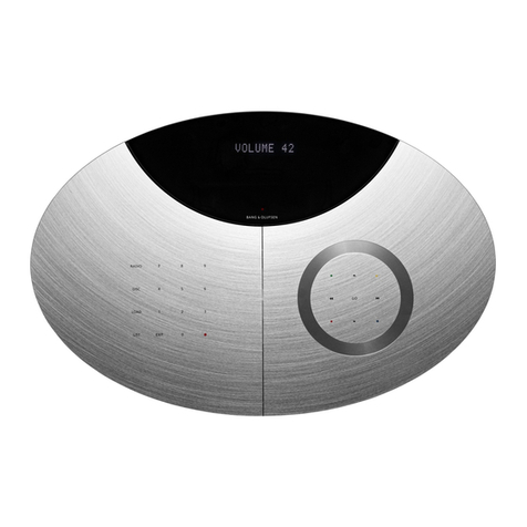
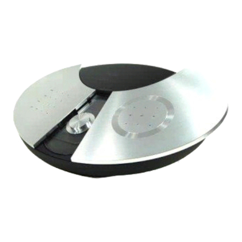
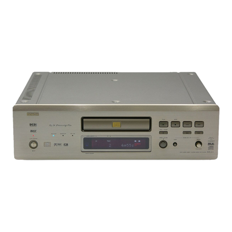
Bang & Olufsen DVD 1 MKII Service manual

DVD 1 MKII
Type 4621 - 4627
Service Center repair guide
English

CONTENTS
English............................................................................................. 1
Disassembly..................................................................................... 8
Specication guidelines for service use ........................................ 9
Wiring diagram .............................................................................. 10
Available parts................................................................................ 11
There is no Brief operation guide in this Service Center repair guide.
Instead an english version of the user guide is enclosed the back-up
suitcase.

1.1
SMPS A/V Board
Keyboard & Display
DVD Drive mechanism
DVD
Main board
-
(Mini DIN)
(Phono)
CONTROL
(Mini jack)
(Phono)
MAINS SCART S-VIDEO
VIDEO
DIG. Audio
LINE OUT L RGB,
Y/C,
CVBS
Switch
LINE OUT R
02
01
77
95
03
SERVICE
(Mini jack)
P5
P14P15
P6
P4
P12P9
P10
P16
P11
P13
P1
P2
P1
DVD Drive
P25P22
P9
P8
P4
P2
Survey of modules
Contents, Survey of modules, English
&75/ 6(59,&(
/ ,1 ( 28 75
/ ,1 (28 7/ &9%6
5* %
<&
9,' (2 $9 69,'(2
' ,* 2 8 7
AVIS leectrique ne pas ouvrir
LASER PRODUCT
CLASS 1
CAUTION
RISK OF ELECTRIC SHOCK
DO NOT OPEN
Risque de choc
Complies with FCC rules part 15,
subpart C and J
Complies with 21 CFR
1040.10 and 1040.11
Manufactured under license from
Dolby Laboratories. "Dolby" and the
Double-D symbol are trademarks
of Dolby Laboratories.
Confidential unpublished works.
1992-1997 Dolby Laboratories.
All rights reserved.
Apparatus Claims of U.S. Patent
Nos. 4,631,603,4,577,216,
4,819,098 and 4,907,093 licensed
for limited veiwing uses only.
DOLBY
D I G I T A L
C
D
D
D
D
0$,16
How to service .......................................................................... 1.2
Cautions ................................................................................... 1.3
Service Mode ............................................................................ 1.4
ServiceTool ................................................................................ 1.5
Repair tips ................................................................................. 1.6
Final check after repair .............................................................. 1.7

1.2
1.3
How to service
DVD1 mkII is supposed to be serviced in the customer’s home.
In order to support the general service strategy the Back up suite case contains all
replaceable modules.
The ServiceTool is required in several service situations, e.g.
Error codes – read out and clearing, update of SW or changing the Region setting.
Refer to the ServiceTool for full description of functions and operation.
How to service, English

1.2
1.3
Cautions, English
CLASS 1
LASER PRODUCT
COMPACT
DIGITAL AUDIO
COMPACT
DIGITAL VIDEO
STATIC ELECTRICITY
MAY DESTROY THE
PRODUCT
ESD
Caution
Service
The DVD1 may only be serviced by qualied technical personal.
The product contains a laser system and is classied as a class 1 laser product
The use of any controls, adjustments or procedures other than those specied
herein may result in hazardous radiation exposure.
This product incorporates copyright protection technology that is protected by
claims of certain US patents and other intellectual property rights owned by
technology must be authorized by Macrovision Corporation, and is intended for
home and other limited viewing uses only unless otherwise authorized by
Macrovision Corporation. Reverse engineering or disassembly is prohibited.
Warning
Static electricity
Static electricity may damage the product.
Static-protective eld service kit.
A static-protective eld service kit must always be used when the product is
disassembled or modules are being handled.
The modules must always be connected to the static-protective eld service kit or
placed in an ESD-proof bag.
Follow the instructions in the guide and use the ESD-mat for both old and new
modules.
Please note:
When mains voltage on the DVD1 is required, remove the connection between the
DVD1 and the ESD-mat.

1.4
1.5
Service Mode
Software version.
Read SW version
- Remove CD/DVD from loader.
- Disconnect the mains supply.
- Press and hold [PLAY] and [<<].
- Connect to the mains supply.
- Switch on the mains supply.
The software version is displayed on the Display.
Memory clear.
Memory clear resets the Initial Settings to the default setting.
The Region setting is not affected by the Memory clear.
- Insert CD/DVD into loader.
- Disconnect mains supply.
- Press and hold [PLAY] and [>>].
- Connect to the mains supply.
- Switch on the mains supply.
- Hold [PLAY] and [>>] until DVD player starts to play, approx. 6 sec.
Service Mode, English

1.4
1.5
ServiceTool
Considerations before connecting the ServiceTool to the product.
- Disconnect the product from the Mains supply.
- Follow the instructions described in the ServiceTool.
Contents in Servicetool.
The ServiceTool will contain the complete information concerning:
- How to connect the ServiceTool to the product.
- List of functions handles by the ServiceTool.
- Detailed instruction for using the functions.
The ServiceTool does not contain:
- Description of access and connection to internal connectors inside the product.
ServiceTool, English

1.6
1.7
Repair tips
Picture
Poor picture
Dirt on lens
The laser lens must never be touched !
Refer to “Optical Disc Reference Book” for full description.
The “Optical Disc Reference Book” is available in the following languages:
English (Part no. 3540685), German (Part no. 3540686), French (Part no.
3540687), Danish (Part no. 3540688), Italian (Part no. 3540689), Spanish (Part no.
3540690), Nederland (Part no. 3540691)
Dirt/defect disc
Refer to user guide for cleaning the disc.
Pixel error or frozen picture is typically due to DVD mechanism failure.
Repair Tips, English
Summary from Optical Disc Reference Book
Optical unit
The optical unit, also called the OPU - Optical Pick-Up Unit - with actuator, laser
optics and belonging electronics is the single most expensive and delicate part of
the DVD mechanism. It is especially the OPU which must be protected against
unintentional contact, dust or other pollution during storage, transport,
production and service.
Furthermore, special care must be taken to prevent ElectroStatic Discharge (ESD).
The laser lens must never be touched!
The actuator (the motion mechanism for the lens/mirror system) has together
with the complete OPU been adjusted by the supplier. The adjustment is xed
and is not supposed to be readjusted. Please also take note that the actuator
includes magnets which may attract iron particles from screw-cuttings etc. and
this may detriment the function of the actuator. Furthermore, please avoid that
other magnets, in for instance loudspeakers or magnetic screw drivers get into
close contact with the OPU. The OPU which has been adjusted individually
together with the mechanism itself cannot be readjusted, repaired or replaced.
Cleaning and test of the OPU
Because of the design of the lens it can be very difcult to determine whether
the lens is dirty, therefore always clean the lens when servicing. A nger print on
the lens will, like dust and other contaminants affect the performance of the
lens negatively. If a contamination has taken place the lens can be cleaned with
care. Loose particles usually can be removed with air (use e.g. a blower brush for
camera lenses). Finger prints etc. can be removed with a special cleaning uid -
“Kodak Lens Cleaner CAT 176 71 36” - on a cotton bud (e.g. of the ESD safe
wooden type).
Clean the lens by dipping the cotton bud “Kodak Lens Cleaner CAT 176 71 36”
and carefully wipe it with circular movements. Remove the moisture on the lens
with the dry end of the cotton bud.

1.6
1.7
No picture
DVD mechanism failure
DVD main board failure
AV Board failure
Power supply failure
Refer to wiring diagram for point of measurement.
1. Check Video signal on selected output.
RGB AV connector
CVBS Video
YC S-Video
2. Check Video signal, RGB or YC on input to AV Board.
R, G, B and Y, C
3. Check power supply to DVD Main board
RGB OK and CVBS failure.
Video buffer on AV Board defect – Replace PCB2, AV Board.
Power supply check
SMPS output
Supply power for DVD main board and mechanism.
2P15
Sound
DVD or CD sound
The DVD Main Board delivers a digital audio signal to the AV Board.
Analog audio signal are measured on the output sockets.
Play DVD/CD
1. Check Audio signal on selected output
Line out R / L, AV or DIG. OUT.
2. Check power supply to DVD Main Board.
Display/Keyboard
Refer to wiring diagram for measuring points.
1. Check +5V supply.
2. Check for activity on KCLK_Display, KDATA_Display and CS_Display.
3. Check function of keys, shift to low voltage when activated.
Loader/Tray
Mechanical failure
No power from AV Board
1P5 pin 1 LOADER_MOTOR - 3.6V open
1P5 pin 2 LOADER_MOTOR+ 3.6V close
No function
Check power supply.
Repair Tips, English

1.8
Final Check after repair
Insulation test
DVD 1 must be insulation tested if it has been dismantled.
Make the test when the DVD 1 is reassembled and is ready to be returned to the
customer.
Insulation test
- Short-circuit the two pins of the mains plug and connect them to one of the
terminals of the Insulation tester. Connect the other terminal of the insulation
tester to ground on the DIGITAL OUTPUT socket.
- To avoid damaging the DVD 1, it is essential to ensure that both terminals of the
insulation tester have good contact.
- Slowly turn up the voltage control of the insulation tester until a voltage of 2.5kV(ac) is
obtained.
- Maintain that voltage level for one second, then slowly turn it down again.
- During the testing the current must not exceed 10mA.
Please note:
Avoid all skin contact with the AC plug and all other metal parts while performing
the test, as this contact may inuence the measurement.
Conrm picture and sound
DVD
Conrm the region setting is correct, use a DVD with the correct region.
CD
Conrm audio sound, use a CD.
Error log.
Clear the error log. Use the ServiceTool.
Customer setup.
Remember to inform the customer of any changes that has been made in the user
setup, due to service procedures, such as “Memory clear”.
Restore the customers setup.
Clean the DVD1.
Wipe dust off the surface off DVD 1 using a dry, soft cloth. If necessary, remove
grease stains or more persistent dirt with a rmly wrung soft cloth which you have
dipped in a solution of water containing a few drops of mild detergent.
Never use alcohol or other solvents to clean any part of DVD 1.
Final Check after repair, English

Both sides of DVD1
8.1
Disassembly
Disassembly
TX10
TX10
TX10TX10

PCB1 Swich Mode Power supply PCB2 A/V Board
8.2 Replacement of PCB1, PCB2
1P2
TX10
2x
2P5
2P14
2P15
2P6
2P4
2P13
TX10
6x

Replacement of PCB3 8.3
Push to "unlock" front
PCB3 Keyboard & Display
2P4
TX10
3x

8.5
8.4 Replacement of PCB77
PCB77 DVD Main board
TX10
4x
TX10
1x
77P8
77P9
77P22
77P25
77P22
77P25
3x
95P106
1
2
3
4
5
6
When reconnecting
- be sure to connect cables correct

8.5
J
OldNew
New
Old
Place cables so they are placed the same
way as on the old mechanism
When reconnecting
- be sure to connect cables correct
Replacement of PCB95
PCB95 DVD Mechanism
77P8
Remove PCB77 DVD Main board (1 - 5)

8.6

9.1
SPECIFICATION GUIDELINES FOR SERVICE USE DVD 1 MKII
DVD Region * See type survey
Cabinet nish Black, Silver
Operation Close-up operation
Beo 4, Beo 1 remote control via BeoVison recommended
Disc size 12 cm. - 8 cm
Audio frequency response 4 -20,000 Hz
Playback the following DVD-Video, Video CD, CD-A, CD-R, CD-RW, CD-MP3
Multistandard PAL/NTSC
Signal/noise ratio Audio ≥ 110 dB, A weighted
Dimensions W x H x D/Weight 38 x 9.7 x 28 cm/4.0 kg
Power supply 100-120 volts or 220-240 volts/50/60 Hz (* See type survey)
Power consumption Typical 13 watts / st-by < 1 watt
Connections
AV Pin 1 Audio R out 1.8V RMS 1k ohm
Pin 2 Not used
Pin 3 Audio L out 1.8V RMS 1k ohm
Pin 4 Audio GND
Pin 5 Blue GND
Pin 6 Not used
Pin 7 Blue out 0.7 Vpp 75 ohms
Pin 8 OV / 6V (16:9) / 12V (4:3)
Pin 9 Green GND
Pin 10 Not used
Pin 11 Green out 0.7 Vpp 75 ohms
Pin 12 Not used
Pin 13 Red GND
Pin 14 Blanking GND
Pin 15 Red out 0.7 Vpp 75 ohms
C out 0.3 Vpp 75 ohms
Pin 16 Blanking out 75 ohms Logic 0 = 0V to 0.4V
Logic 1 = 1V to 3V
Pin 17 Video out GND
Pin 18 Video in GND
Pin 19 Composite video out 1 Vpp 75 ohms
Y out 1 Vpp 75 ohms
Pin 20 Not used
Pin 21 Shield
S-VIDEO Pin 1 Y GND
Pin 2 C GND
Pin 3 Y out 1 Vpp 75 ohms
Pin 4 C out 0.3 Vpp 75 ohms
VIDEO Composite video out 1 Vpp 75 ohms
DIG. OUT Digital audio output 0.5 Vpp ± 20%
LINE OUT L & R Audio L & R out 1.8 V RMS 100 kohm
CTRL AVL 9.5 V - 12 V 4:3 (Logic 1)
5 V - 7 V 16:9
0 V - 2 V Logic 0
SERVICE ATI
Subject to change without notice
Specication guidelines for service use

9.2
* Type survey
Type Market DVD Region Mains voltage
4621 Austria, Bahrain, Belgium, Croatia, Czech Repub., Denmark, Egypt, Finland, 2 220-240 Volts
France, Germany, Greece, Holland, Hungary, Israel, Italy, Kuwait, Lebanon,
Norway, Oman, Poland, Portugal, Qatar, Saudi Arabia, Slovak Rep., Slovenia,
South Africa, Spain, Sweden, Switzerland, Turkey, UK, United Arab Emirates
4622 Taiwan 3 100-120 Volts
4623 Hong Kong, Indonesia, Malaysia, Singapore, Thailand 3 220-240 Volts
4624 Brazil, Mexico 4 100-120 Volts
4625 Argentina, Australia, Chile, New Zealand, Peru, Uruguay 4 220-240 Volts
4626 Morocco, Russia 5 220-240 Volts
4627 China 6 220-240 Volts
Mains voltage
100 - 120 V
220 - 240 V
1J2
Type survey
1J2
1J2

10.1 Wiring diagramWiring diagram 10.1 10.1
Wiring diagram
6200075
W02
6200076
W03
6277197
W04
6277194
W01OEM
CNa
<
>
<
>
<
<
<
<
>
<
<
<
>
<
>
<
>
>
>
>
>
<
>
<
>
<
<
>
<
>
<
>
>
>
>
>
<
>
<
>
<
<
<
>
<
<
<
<
>
<
>
<
OEM CN8
95
DVD DRIVE MECHANISM
Solder
>
>
>
<
<
<
<
<
<
>
>
<
OEM
<
>
<
<
<
<
<
<
<
>
>
>
CN2
Solder
>
>
>
>
W07
OEM
OEM
W08
OEM
W09
OEM
>
>
>
>
CN4
6277199
W05P601
>
>
<
>
<
P5
>
>
<
>
<
DVD MAIN BOARD
77
OEM
CN22
>
>
>
>
>
>
>
>
>
>
>
>
>
>
>
>
>
>
>
>
>
<
>
<>
<>
>
>
>
<
<
<
<
>
>
>
<>
<>
<
>
>
>
>
>
>
>
>
>
>
>
>
>
>
>
>
>
>
>
>
>
>
P15
<>
<>
<>
<
<
<
<
<
<
<
<
<
<
<
<
<
<
<
<
<
<
<
<
<
<
<
OEM
CN25
P14
<
<
<
<
<
<
<
<
<
<
<
<
<
<
<
<
<
<
<
<
<
<
<
<>
<>
<>
>
>
<
<
<
CN9 OEM
P6
<
<
<
>
>
>
<
<
<
<
<
>
>
>
>
>
>
P1
P4
>
>
>
>
>
>
<
<
<
<
<
>
W06
6200077
KEYBOARD & DISPLAY
03
AV BOARD
02
>
>
>
<
>
>
>
>
>
>
>
>
>
>
P13
P2
>
>
>
>
>
>
>
>
>
>
<
>
>
>
<
<
>
<
>
P8
P7
>
<
<
<
>
>
<
01
SMPS

11.1 List of available partsList of available parts 11.111.1
AVAILABLE PARTS
DVD 1 MKII
DVD 1 9001 3400482 Top cover, black
3400487 Top cover, silver
9002 3451358 Iron chassis
9003 3320756 Side panel, left
9004 3320755 Side panel, right
9005 3451357 Front panel w/buttons
1Module 8006898 PCB1, Switch Mode Power Supply
7221406 PCB1, Jumper for 115V mains conversion
2Module 8001444 PCB2, A/V Board
3Module 8001346 PCB3, Keyboard
77Module 8001347 PCB77, DVD Mainboard
95Module 8001355 DVD Mechanism
9001
9002
9003
9004
9005
2
1
3
Wire bundles See wiring diagram page 3.1.
The part no. is printed on the diagram above the wire bundle, as shown.
6277197
W04
>
>
<
<
<
CN9 OEM
P6
<
<
<
>
>
Parts not shown 6100245 Mains lead EU
6100328 Mains lead GB
6100248 Mains lead AUS
6100040 Mains lead CHN
6100306 Mains lead US
6270803 AV cable
6270804 Data cable 10cm w. mini jack
6270775 SPDIF cable
3375258 Bag w/screws and washers
3395242 Back-up suitcase
Packing 3396135 Set of foam
3392509 Outer carton
Available documentation See Retail System
77
95
Table of contents
Other Bang & Olufsen DVD Player manuals

Bang & Olufsen
Bang & Olufsen BeoCenter 2 MK II User manual

Bang & Olufsen
Bang & Olufsen BeoCenter 2 Assembly instructions

Bang & Olufsen
Bang & Olufsen DVD 2 User manual

Bang & Olufsen
Bang & Olufsen BeoMedia 1 User manual

Bang & Olufsen
Bang & Olufsen UG4 User manual

Bang & Olufsen
Bang & Olufsen DVD 2 User manual

Bang & Olufsen
Bang & Olufsen DVD 1 User manual