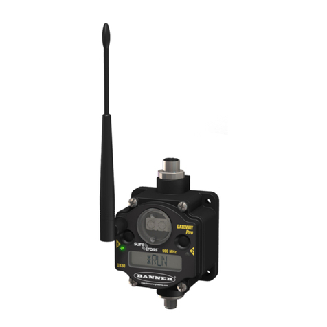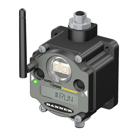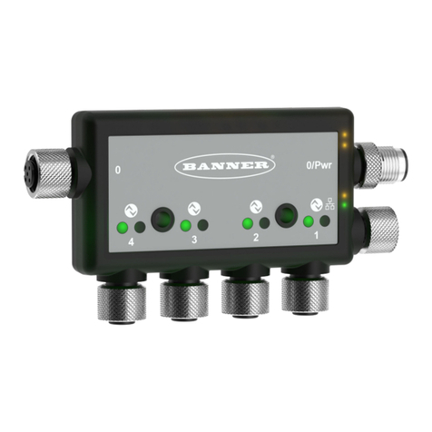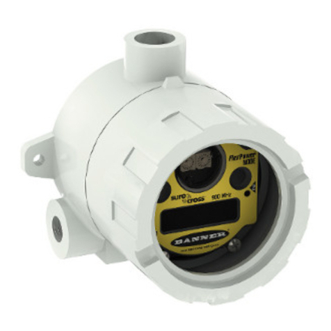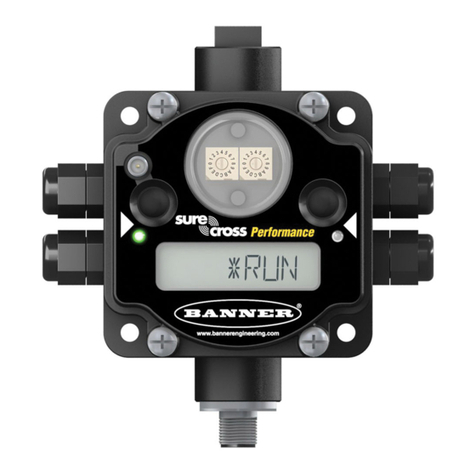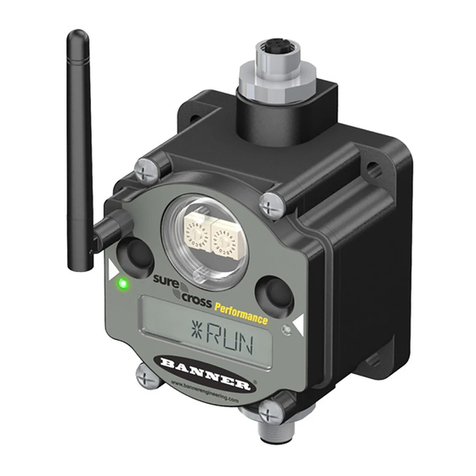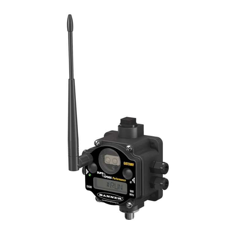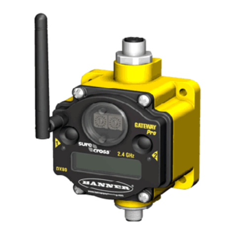
Point Away From Direct Sunlight. When you are not using a secondary enclosure, mini-
mize the damaging effects of ultra-violet radiation by mounting the devices to avoid facing
intense direct sunlight.
• Mount under an overhang or other source of shade,
• Install indoors, or
• Face the devices north when installing outside.
For harsh outdoor applications, consider installing your radio inside a secondary enclosure.
For a list of available enclosures, refer to the Accessories list.
Mount Vertically to Avoid Collecting Rain. When possible, mount the devices where rain
or snow will drain away from the device.
• Mount vertically so that precipitation, dust, and dirt do not accumulate on permeable
surfaces.
• Avoid mounting the devices on flat or concave surfaces, especially if the display will be
pointing up.
Moisture and Condensation. If condensation is present in any device, add a small desic-
cant packet to the inside of the radio.
To help vent the radios, Banner also sells a vented plug (model number BWA-HW-031) for
the 1/2" NPT port of the SureCross radios.
Vented plug for the 1/2" NPT port.
Watertight Glands and NPT Ports
Watertight Glands and Plugs
To make glands and plugs watertight, use PTFE tape and follow these steps.
To make the glands watertight:
1. Wrap four to eight passes of polytetrafluoroethylene (PTFE) tape around the
threads as close as possible to the hexagonal body of the gland.
2. Manually thread the gland into the housing hole. Never apply more than 5 in-
lbf of torque to the gland or its cable clamp nut.*
Seal any unused PG-7 access holes with one of the supplied black plastic plugs. To install a watertight PG-7 plug:
1. Wrap four to eight passes of PTFE tape around the plug’s threads, as close as possible to the flanged surface.
2. Carefully thread the plastic plug into the vacant hole in the housing and tighten using a slotting screwdriver. Never apply more than
10 in-lbf torque to the plastic plug.
* This is not a lot of torque and is equivalent to the torque generated without using tools. If a wrench is used, apply only very light pres-
sure. Torquing these fittings excessively damages the device.
Watertight NPT Plugs
Seal the 1/2” NPT port if it is not used. To install a watertight NPT plug:
1. Wrap 12 to 16 passes of PTFE tape evenly across the length of the threads.
2. Manually thread the plug into the housing port until reaching some resistance.
3. Using a 9/16” crescent wrench, turn the plug until all the plug’s threads are engaged by the housing port or until the resistance
doubles. Do not overtighten as this will damage the SureCross unit. These threads are tapered and will create a waterproof seal
without overtightening.
* This is not a lot of torque and is equivalent to the torque generated without using tools. If a wrench is used, apply only very light pres-
sure. Torquing these fittings excessively damages the device.
SureCross DX70 Wireless Point-to-Point Kits
P/N 133214 rev. H www.bannerengineering.com - tel: 763-544-3164 7
