Banner SSA-EB Series User manual

Instruction Manual
30 mm Panel Mount Electro-Mechanical Push Buttons
• Four styles of actuators: standard, illuminated, lockable, and illuminated lockable
• Push-to-stop, twist-to-release (standard and lockable), or pull-to-release (standard)
operation per IEC 60947-5-5
• Latching design complies with ISO 13850; direct (positive) opening operation per EN
60947-5-1
• Compliant with ANSI B11.19, NFPA 79, and IEC/EN 60204-1 Emergency Stop
requirements
• “Safe Break Action” ensures normally closed (NC) contacts will open if the contact block
is separated from the actuator
• Panel mount though 30 mm mounting hole
• "Emergency Stop" legend optional
Models SSA-EB… series are "mushroom-style" electro-mechanical emergency stop push buttons. These buttons mount through a
30 mm hole in an enclosure. When the button is armed, the switch's safety contacts (normally closed/NC) are closed and its
monitoring contacts (normally open/NO), if present, are open. When the button is pushed, the switch's safety contacts open, and the
monitoring contacts close. The contacts remain in this condition until they are manual rearmed.
The standard 40 mm and 60 mm actuators can be rearmed by pulling or twisting clockwise the red actuator. The lockable 44 mm
actuator can be rearmed only by twisting the actuator clockwise. Do not pull the actuator while twisting or the switch may be
damaged, causing a malfunction or operational failure. The illuminated models provide a red indication within the face of the button
that allows for easy identification of a pushed/actuated button.
SSA-EB1M… series padlock-style lockable emergency stop push buttons are intended to prevent unauthorized or accidental
resetting of a pushed/latched button. The SSA-EB1M… series are not to be used as an energy isolating device or as the sole means
of complying with Lockout/Tagout or with the requirements of the isolation of hazardous energy (see OSHA 29CFR1910.147, ANSI
Z244.1, CSA Z460, ISO 14118). The locking feature can be used to provide supervisory/personal control and provide an additional
safety measure(s) to reduce the likelihood of inadvertent arming and energization of the emergency stop circuit.
Models
Table 1: Non-illuminated models
Standard 40 mm Standard 60 mm Lockable 44 mm Safety Contacts Monitor Contacts
SSA-EB1P-02 SSA-EB2P-02 SSA-EB1MP-02 2 normally closed (NC)
SSA-EB1P-04 SSA-EB2P-04 SSA-EB1MP-04 4 normally closed (NC)
SSA-EB1P-11 SSA-EB2P-11 SSA-EB1MP-11 1 normally closed (NC) 1 normally open (NO)
SSA-EB1P-13 SSA-EB2P-13 SSA-EB1MP-13 3 normally closed (NC) 1 normally open (NO)
SSA-EB1P-22 SSA-EB2P-22 SSA-EB1MP-22 2 normally closed (NC) 2 normally open (NO)
Table 2: Illuminated models
Standard 40 mm Lockable 44 mm LED Safety Contacts Monitor Contacts
SSA-EB1PL1-02 SSA-EB1ML1P-02 Per wiring connection 2 normally closed (NC)
SSA-EB1PL1-04 SSA-EB1ML1P-04 Per wiring connection 4 normally closed (NC)
SSA-EB1PL1-11 SSA-EB1ML1P-11 Per wiring connection 1 normally closed (NC) 1 normally open (NO)
SSA-EB1PL1-13 SSA-EB1ML1P-13 Per wiring connection 3 normally closed (NC) 1 normally open (NO)
SSA-EB1PL1-22 SSA-EB1ML1P-22 Per wiring connection 2 normally closed (NC) 2 normally open (NO)
SSA-EB1PL2-12 SSA-EB1ML2P-12 PUSH ON 2 normally closed (NC) 1 normally open (NO)
ISD Connect—All models with 2 normally closed (NC) contacts can be used with Banner's SSA-ISD-TCA by using an
MQDMC-5xx(RA) series cable.
Important... Read this before proceeding!
The user is responsible for satisfying all local, state, and national laws, rules, codes, and regulations relating to the use of this
product and its application. Banner Engineering Corp. has made every effort to provide complete application, installation, operation,
and maintenance instructions. Please contact a Banner Applications Engineer with any questions regarding this product.
SSA-EB Series Emergency Stop Push Button
Original Document
194992 Rev. D
21 September 2022
194992

The user is responsible for making sure that all machine operators, maintenance personnel, electricians, and supervisors are
thoroughly familiar with and understand all instructions regarding the installation, maintenance, and use of this product, and with the
machinery it controls. The user and any personnel involved with the installation and use of this product must be thoroughly familiar
with all applicable standards, some of which are listed within the specifications. Banner Engineering Corp. makes no claim regarding
a specific recommendation of any organization, the accuracy or effectiveness of any information provided, or the appropriateness of
the provided information for a specific application.
WARNING:
•Not a safeguarding device
• Failure to follow these instructions could result in serious injury or death.
• This device is not considered a safeguarding device because it requires an overt action by an individual
to stop machine motion or hazards. A safeguarding device limits or eliminates an individual's exposure
to a hazard without action by the individual or others. This device cannot be substituted for required
safeguarding. Refer to the applicable standards to determine those requirements.
Emergency Stop Considerations
NFPA 79, ANSI B11.19, IEC/EN 60204-1, and ISO 13850 specify emergency stop requirements, including the following:
• Emergency-stop push buttons shall be located at each operator control station and at other operating stations where
emergency shutdown is required.
• Stop and emergency-stop push buttons shall be continuously operable and readily accessible from all control and operating
stations where located. Do not mute or bypass E-stop buttons.
• Actuators of emergency-stop devices shall be colored red. The background immediately around the device actuator shall be
colored yellow (where possible). The actuator of a push-button-operated device shall be of the palm or mushroom-head
type.
• The emergency-stop actuator shall be a self-latching type.
WARNING:
•Do not mute or bypass any emergency stop device
• Muting or bypassing the safety outputs renders the emergency stop function ineffective.
• ANSI B11.19, NFPA 79 and IEC/EN 60204-1 require that the emergency stop function remains active at
all times.
WARNING:
•Connect two or more devices to the same safety module (controller) in series
• Connecting devices in parallel defeats the switch contact monitoring ability of the module and creates an
unsafe condition that could result in serious injury or death.
• Failure to test each device individually in this manner could result in undetected faults and create an
unsafe condition that could result in serious injury or death.
• Connect the contacts of the corresponding pole of each switch in series. Never connect the contacts of
multiple switches in parallel. Individually actuate (engage) each device, then release (or re-arm) and
reset the safety module. This allows the module to check each switch and its wiring to detect faults.
Perform this check during the prescribed checkouts.
Installation and Maintenance
The device must not be affected by environmental conditions. Install the device so that operation is not impeded, but should be
protected against inadvertent operation (for example, accidental actuation by being bumped or leaned against). Do not operate
the switch using a tool. Do not expose the switch to excessive shocks and vibrations, otherwise the switch may be deformed or
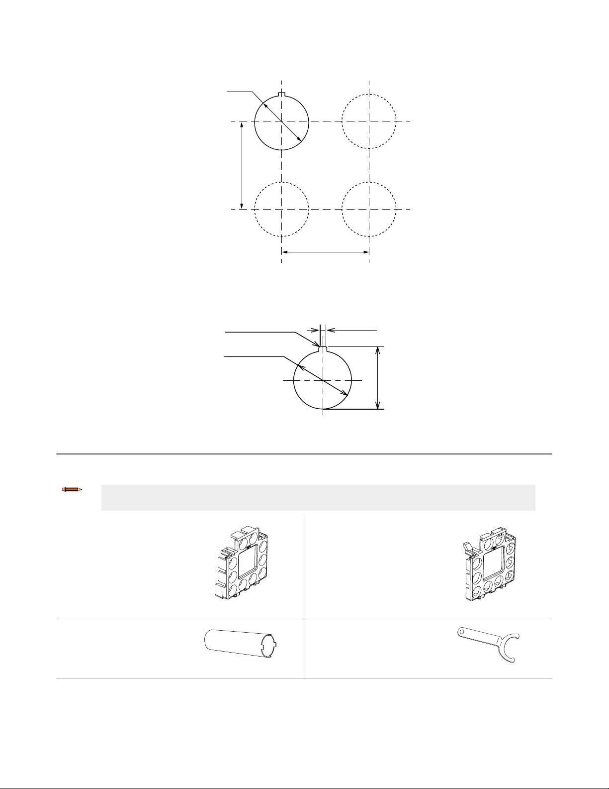
damaged, causing malfunction or operation failure. See Dimensions on page 8.
Electrical installation must be made by qualified personnel 1 and must comply with NEC (National Electrical Code), NFPA 79 or
IEC/EN 60204-1, and all applicable local standards. It is not possible to give exact wiring instructions for a device that interfaces to a
multitude of machine control configurations. The following is general in nature; it is recommended to perform a risk assessment to
ensure appropriate application, interfacing/hookup, and risk reduction (see ISO 12100 or ANSI B11.0).
For SSA-EB1M..-.. series padlock-style lockable emergency stop push buttons, make sure that an applicable padlock and hasp is
used. The total weight of the padlock and hasp must not exceed 1500 g (3.3 lbs) or the switch may malfunction or fail.
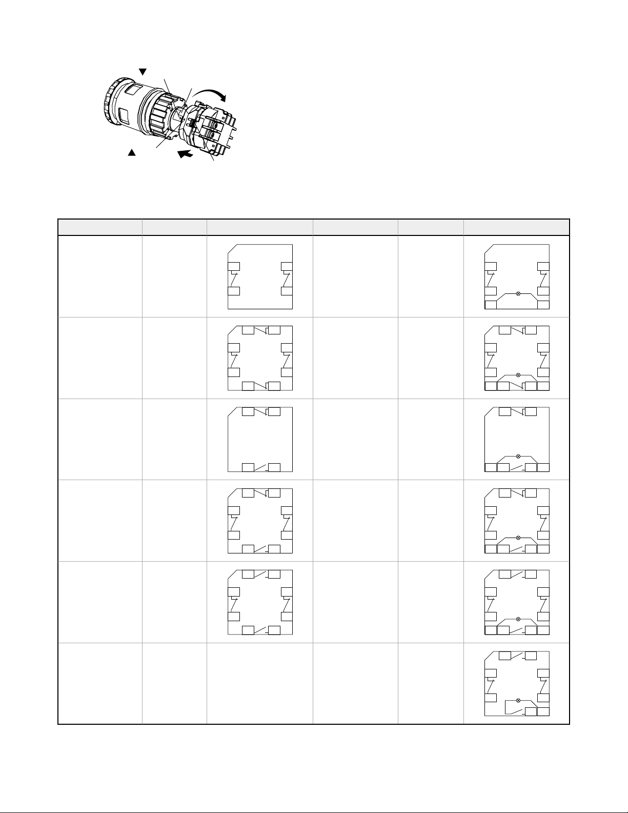
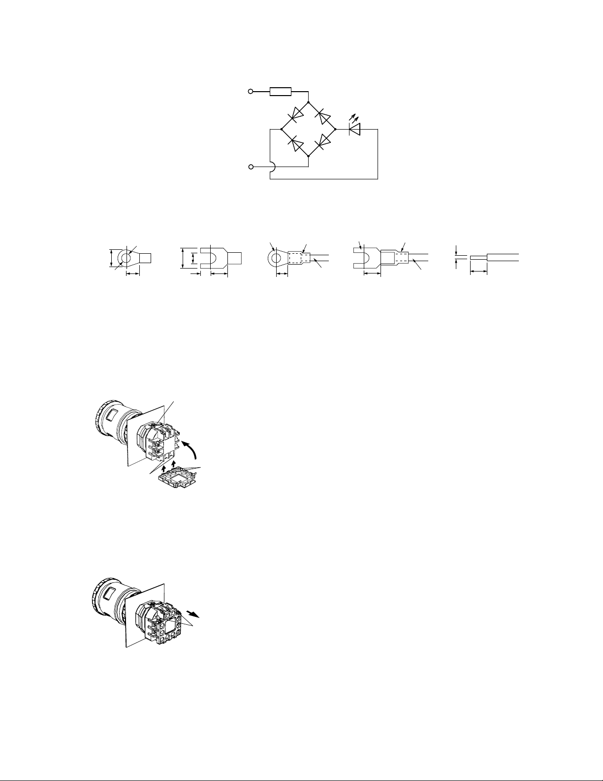
Removing and Installing the Contact Block and Panel Mounting
For more information, please refer to the training video at https://www.youtube.com/watch?v=FjfR6d4ljrA.
1A Qualified Person possesses a recognized degree or certificate or has extensive knowledge, training, and experience to solve problems relating to the
emergency stop installation.
SSA-EB Series Emergency Stop Push Button
2 www.bannerengineering.com - Tel: + 1 888 373 6767 P/N 194992 Rev. D

Remove the Contact Block
1. Arm (reset) the actuator (button). Do not attempt to remove the contact block while the actuator is latched (pushed), or the
switch may be damaged.
2. Grip the beveled surfaces at the corners of the yellow bayonet ring and pull the ring toward the contact block until the latch
pin clicks.
If the switch is not installed, place the contact block against the base of the index finger and grip the bayonet ring with the
thumb, index finger, and middle finger, then squeeze until the click is heard.
3. Rotate the contact block counterclockwise and pull out to remove the contact block. Do not use excessive force when
removing the contact block, or the switch may be damaged.
For illuminated pushbuttons, the LED lamp is built into the contact block. When removing the contact block, pull the contact
block straight to prevent damage to the LED lamp. Do not use excessive force or the LED lamp may be damaged and fail to
light.
When the contact block is removed, the monitor contact (normally open contact) is closed.
Bayonet Ring Beveled Surface
Latch Pin
Contact Block
Pull
Contact Block
Panel Mounting
1. Remove the contact block and the M30 jam nut from the actuator and verify that the rubber gasket is in place.
2. Align the anti-rotation key on the bezel with the keyway (notch) in the panel.
3. Insert the actuator into the hole from the front of the panel, and tighten the M30 jam nut using wrench SSA-EB1-LRW or
SSA-EB1-LRTW to a maximum torque of 2.5 N•m (1.8 ft-lbs).
Note:
• The allowable panel thickness is 1 mm to 5 mm for SSA-EB1P… and 1 mm to 6 mm for SSA-
EB1M….
• Banner recommends that the anti-rotation key/keyway is placed at the top of the hole (0° versus
90° or 180°) so the word “TOP” on the contact block and actuator is on the top so that the
terminal label is easier to read.
• If using ESLP1-30/60-.. Plastic Emergency Stop legend, remove the anti-rotation projection on
the legend using pliers, and then install the legend onto the actuator before inserting it into the
hole.
Install the Contact Block
1. Arm (reset) the actuator (button). Do not attempt to install the contact block while the actuator is latched (pushed), or the
switch may be damaged.
2. Align the small ▼ mark on the edge of the actuator with the small ▲ mark on the yellow bayonet ring. The contact block
(TOP LOCK) should be turned approximately 45° counterclockwise from the anti-rotation key/keyway on the bezel.
3. Hold the black contact block (not the yellow bayonet ring), and slide the contact block onto the actuator. Push until the
actuator is fully inserted into the contact block (the bayonet ring will compress and motion will stop).
Note: If not installed on a panel, press on the actuator’s bezel (not the button).
4. Turn the contact block clockwise until the yellow bayonet ring pops into position and clicks.
When properly seated, the contact block cannot be turned or pulled.
SSA-EB Series Emergency Stop Push Button
P/N 194992 Rev. D www.bannerengineering.com - Tel: + 1 888 373 6767 3

Push
Mark
Mark
TOP Lock
TOP
Turn
Clockwise
Wiring Diagrams
Non-Illuminated Contacts Wiring Illuminated Contacts Wiring
SSA-EB1P-02
SSA-EB1MP-02
2 normally closed
(NC)
12
11
21
22
SSA-EB1PL1-02
SSA-EB1ML1P-02
2 normally closed
(NC)
12
11
21
22
X2X1
LED24V
SSA-EB1P-04
SSA-EB1MP-04
4 normally closed
(NC)
22
11 12
21
41
42
32 31
SSA-EB1PL1-04
SSA-EB1ML1P-04
4 normally closed
(NC)
22
11 12
21
41
42
X23132X1
LED24V
SSA-EB1P-11
SSA-EB1MP-11
1 normally closed
(NC) / 1 normally
open (NO)
11 12
24 23
SSA-EB1PL1-11
SSA-EB1ML1P-11
1 normally closed
(NC) / 1 normally
open (NO)
11 12
X22324X1
LED24V
SSA-EB1P-13
SSA-EB1MP-13
3 normally closed
(NC) / 1 normally
open (NO)
22
11 12
21
41
42
34 33
SSA-EB1PL1-13
SSA-EB1ML1P-13
3 normally closed
(NC) / 1 normally
open (NO)
22
11 12
21
41
42
X23334X1
LED24V
SSA-EB1P-22
SSA-EB1MP-22
2 normally closed
(NC) / 2 normally
open (NO)
22
13 14
21
41
42
34 33
SSA-EB1PL1-22
SSA-EB1ML1P-22
2 normally closed
(NC) / 2 normally
open (NO)
22
13 14
21
41
42
X23334X1
LED24V
SSA-EB1PL2-12
SSA-EB1ML2P-12
(Push ON LED)
2 normally closed
(NC) / 1 normally
open (NO)
22
13 14
21
31
32
X2X1
LED24V
SSA-EB Series Emergency Stop Push Button
4 www.bannerengineering.com - Tel: + 1 888 373 6767 P/N 194992 Rev. D

Figure 1. LED unit internal circuit
X1
X2
LED
R
Figure 2. Applicable Crimping Terminal
ø3.2 min.
ø6.0 max.
4.7 min. 3.0 max.
6.0 max.
3.2 max.
4.7 to 5.9
Insulation Tube
Crimping
Terminal
Ring Terminal Spade Terminal Solid Wire
Wire
4.7 to 5.9 4.7 to 5.9 6.2 max.
Insulation Tube
Crimping
Terminal
Wire
ø1.2 max.
Banner recommends the use of crimp terminals with stranded wire or solid core wire to prevent short circuits between terminals.
Ensure that the insulation tube is installed on crimp terminals.
Installing and Removing the Terminal Cover
Install the SSA-EB1-TC Terminal Cover
1. Align the TOP mark on the SSA-EB1-TC terminal cover with the TOP mark on the contact block.
2. Place the two projections on the bottom of the contact block into the slots in the SSA-EB1-TC terminal cover.
Place projections
on contact block
Press on the
terminal cover
TOP Mark
Slots
3. Press the SSA-EB1-TC terminal cover toward the contact block.
Remove the SSA-EB1-TC Terminal Cover
1. Pull out the two latches on the top of the SSA-EB1-TC terminal cover. Do not exert excessive force on the latches, or the
latches may break.
Projections
(pull)
2. Remove the SSA-EB1-TC terminal cover.
SSA-EB Series Emergency Stop Push Button
P/N 194992 Rev. D www.bannerengineering.com - Tel: + 1 888 373 6767 5

Install the IP20 Fingersafe SSA-EB1-FSTC Terminal Cover
The SSA-EB1-FSTC terminal covers cannot be installed after wiring. After installation, the SSA-EB1-FSTC terminal cover cannot be
removed.
With the SSA-EB1-FSTC terminal cover installed, crimping terminals cannot be used. Use solid wires.
Make sure that the SSA-EB1-FSTC terminal cover is securely installed. IP20 cannot be achieved when installed loosely, and electric
shocks may occur.
WARNING:
•Risk of electric shock
• Use extreme caution to avoid electrical shock. Serious injury or death could result.
• Always disconnect power from the safety system (for example, device, module, interfacing, etc.),
guarded machine, and/or the machine being controlled before making any connections or replacing any
component. Lockout/tagout procedures might be required. Refer to OSHA 29CFR1910.147, ANSI
Z244-1, or the applicable standard for controlling hazardous energy.
• Make no more connections to the device or system than are described in this manual. Electrical
installation and wiring must be made by a Qualified Person 2 and must comply with the applicable
electrical standards and wiring codes, such as the NEC (National Electrical Code), NFPA 79, or IEC
60204-1, and all applicable local standards and codes.
1. Align the TOP mark on the cover with the TOP mark on the contact block.
2. Press the cover toward the contact block.
TOP Mark
Press
TOP Mark
Checkout
At machine set up, a Designated Person 3 should test each safety point for proper machine shutdown response. A Designated
Person should check the safety point for proper operation, physical damage, button looseness, and excessive environmental
contamination. This should take place on a periodic schedule determined by the user, based on the severity of the operating
environment and the frequency of switch actuations.
Adjust, repair, or replace components as needed. If inspection reveals contamination on the switch, thoroughly clean the switch and
eliminate the cause of the contamination. Replace the switch and/or appropriate components when any parts or assemblies are
damaged, broken, deformed, or badly worn; or if the electrical/mechanical specifications (for the environment and operating
conditions) have been exceeded.
Always test the control system for proper functioning under machine control conditions after performing maintenance, replacing
the safety point, or replacing any component of the device.
2A person who, by possession of a recognized degree or certificate of professional training, or who, by extensive knowledge, training and experience, has
successfully demonstrated the ability to solve problems relating to the subject matter and work.
3A Designated Person is identified in writing by the employer as being appropriately trained to perform a specified checkout procedure. A Qualified Person
possesses a recognized degree or certificate or has extensive knowledge, training, and experience to solve problems relating to the emergency stop
installation.
SSA-EB Series Emergency Stop Push Button
6 www.bannerengineering.com - Tel: + 1 888 373 6767 P/N 194992 Rev. D

Specifications
Button/Locking Collar
Polyamide/Aluminum
Insulation Resistance
100 MΩ minimum (500 V DC megger)
Rated Current (Ith)
5A
Impulse Withstand Voltage
2.5 kV
Pollution Degree
3
Overvoltage Category
II
Vibration Resistance
Operating extremes: 10 Hz to 500 Hz, amplitude 0.35 mm acceleration 50
m/s2
Shock Resistance
Operating extremes: 150 m/s2 (15G)
Direct Opening
Force: 80 N Minimum
Travel: 4.0 mm Minimum
Button Travel
4.5 mm Maximum
Contact Resistance
50 mOhm maximum (initial value)
Operating Frequency
900 operations/hour
LED Color
Red (The LED is built into the contact block and cannot be replaced)
LED Voltage/Maximum Current
24 V AC/DC ±10%, 15 mA
Total Weight of Padlock and Hasp (SSA-EB1M..-.. only)
1500 g (3.3 lb) maximum
Rated Insulation Voltage (Ui)
250 V
Operating Humidity
45% to 85% RH (no condensation)
Contact Material/Bounce 4
Gold plated silver / 20 ms
Electrical Rating
Minimum load: 1 mA at 5 V AC/DC
Maximum Rated Load: See table
UL Applications: 1.5 A at 250 V AC, 1 A at 30 V DC (pilot duty)
CE Applications: AC-15: 1.5 A at 250 V AC, DC-13: 1 A at 30 V DC
Electrical Life
100,000 operations minimum, 250,000 operations minimum at 24 V
AC/DC, 100 mA
Output Configuration
See Installation and Maintenance on page 2
Mechanical Life
250,000 operations
Terminals
M3 screw terminal (terminal cover included)
Recommended Torque: 0.6 to 1.0 N·m (5.3 to 8.8 in-lbf)
Allowable Wire: 0.75 to 1.25 mm2 (18 to 16 AWG)
B10d
100,000 (based on ISO13849-1(2006))
Operating Temperature
Non-illuminated: –25 °C to +60 °C (–13 °F to +140 °F)
Illuminated: –25 °C to +55 °C (–13 °F to +131 °F)
Environmental Rating
Actuator: IP65 (IEC 60529)
Terminal: IP20 with SSA-EB1-FSTC installed
Standards
Design and Compliance: EN/IEC 60497-5-1, EN/IEC 60947-5-5, UL 508, CSA
C22.2 No.14
Application and Other Applicable Standards (not all inclusive): ISO 13850,
ANSI B11.19, IEC 60204-1, NFPA79
Date code format (U.S. Standard Format)
YYWWX: 2-digit year, 2-digit week, "X” internal code
Certifications
S
Banner Engineering Europe Park Lane,
Culliganlaan 2F bus 3, 1831 Diegem,
BELGIUM
Turck Banner LTD Blenheim House,
Blenheim Court, Wickford, Essex SS11 8YT,
Great Britain
4When the button is reset, the normally closed contacts will chatter. When pressing the button, the normally open contacts will chatter. When designing a control circuit, take the contact chatter time
into consideration. Do not expose the switch to external shocks, otherwise the contacts will bounce.
SSA-EB Series Emergency Stop Push Button
P/N 194992 Rev. D www.bannerengineering.com - Tel: + 1 888 373 6767 7

Rated Operating Voltage (Ue) and Current
Safety Contact (N.C.) 30 V 125 V 250 V
AC 50/60 Hz
Resistive Load (AC-12) - 5 A 3 A
Inductive Load (AC-15) - 3 A 1.5 A
DC
Resistive Load (DC-12) 2 A 0.4 A 0.2 A
Inductive Load (DC-13) 1 A 0.22 A 0.1 A
Monitor Contacts (N.O.) 30 V 125 V 250 V
AC 50/60 Hz
Resistive Load (AC-12) - 1.2 A 0.6 A
Inductive Load (AC-14) - 0.6 A 0.3 A
DC
Resistive Load (DC-12) 2 A 0.4 A 0.2 A
Inductive Load (DC-13) 1 A 0.22 A 0.1 A
The operating current is classified according to EN 60947-5-1 making and breaking capacities and are measured at resistive/inductive load types specified in
EN 60947-5-1. See "Electrical Rating" above for specific model and UL/CE maximum ratings.
Required Overcurrent Protection
WARNING: Electrical connections must be made by qualified personnel in accordance with local and national electrical codes and
regulations.
Overcurrent protection is required to be provided by end product application per the supplied table.
Overcurrent protection may be provided with external fusing or via Current Limiting, Class 2 Power Supply.
Supply wiring leads < 24 AWG shall not be spliced.
For additional product support, go to www.bannerengineering.com.
Supply Wiring (AWG) Required Overcurrent Protection (Amps)
20 5.0
22 3.0
24 2.0
26 1.0
28 0.8
30 0.5
Dimensions
SSA-EB Series Emergency Stop Push Button
8 www.bannerengineering.com - Tel: + 1 888 373 6767 P/N 194992 Rev. D

All measurements are listed in millimeters [inches], unless noted otherwise.
ab c d
7 mm max 19 mm max 39 mm min 15 mm min 5
Mounting Hole Layout
The values are the minimum dimensions for mounting with other ø 30 mm push buttons. For other control units of different sizes and
styles, determine the values according to the dimensions, operation, and wiring convenience.
For padlock-style lockable emergency stop push buttons, determine the values according to the size and number of padlocks and
hasp.
5Dimension d is 6 mm or more when attaching a padlock from the side of a switch
SSA-EB Series Emergency Stop Push Button
P/N 194992 Rev. D www.bannerengineering.com - Tel: + 1 888 373 6767 9

Figure 3. Mounting hole layout
70 mm
minimum
70 mm
minimum
Ø30.5
Figure 4. Notch dimensions
φ 30.5
R0.8
maximum 4.8 +0.2
0
+0.5
0
33.0 +0.5
0
Accessories
Note: Actuators and contact blocks (including LED indicators) are only available as complete units and are not
sold separately.
SSA-EB1-FSTC
IP20 Finger-safe terminal cover
SSA-EB1-TC
Standard terminal cover
(supplied)
SSA-EB1-LRW
Jam nut wrench
SSA-EB1-LRTW
Jam nut twist wrench
SSA-EB Series Emergency Stop Push Button
10 www.bannerengineering.com - Tel: + 1 888 373 6767 P/N 194992 Rev. D

ESLP1-30/60-NW
• E-Stop Legend, Plastic
• Blank
• 60 mm diameter (OD)
• 30 mm hole
ESLP1-30/60
• E-Stop Legend, Plastic
• "Emergency Stop”
• 60 mm diameter (OD)
• 30 mm hole
ESL-41/60 (1 each)
ESL-41/60-10 (10 each)
• E-Stop Legend, Label
• "Emergency Stop”
• 60 mm diameter (OD)
• 41 mm hole for
application around
SSA-EB1P…
ESL-41/60-ENES (1 each)
ESL-41/60-ENES-10 (10 each)
• E-Stop Legend, Label
• "Emergency Stop -
Parada de Emergencia”
• 60 mm diameter (OD)
• 41 mm hole for
application around
SSA-EB1P…
ESL-44/70 (1 each)
ESL-44/70-10 (10 each)
• E-Stop Legend, Label
• "Emergency Stop”
• 70 mm diameter (OD)
• 44 mm hole for
application around
SSA-EB1M…
E
M
E
R
G
E
N
C
Y
S
T
O
P
E
M
E
R
G
E
N
C
Y
S
T
O
P
w
w
w
.
b
a
n
n
e
r
e
n
g
i
n
e
e
r
i
n
g
.
c
o
m
ESC-1-YW
• Emergency stop cover
• 72 mm wide; 30 mm center hole
• For use on standard (non-lockable)
40mm models
U.S. Application Standards
ANSI B11.0 Safety of Machinery, General Requirements, and Risk Assessment
ANSI B11.19 Performance Criteria for Safeguarding
NFPA 79 Electrical Standard for Industrial Machinery
International/European Standards
EN ISO 12100 Safety of Machinery – General Principles for Design — Risk Assessment and Risk Reduction
ISO 13850 (EN 418) Emergency Stop Devices, Functional Aspects – Principles for Design
IEC 62061 Functional Safety of Safety-Related Electrical, Electronic and Programmable Control Systems
EN ISO 13849-1 Safety-Related Parts of Control Systems
IEC/EN 60204-1 Electrical Equipment of Machines Part 1: General Requirements
EN 60947-1 Low Voltage Switchgear – General Rules
EN 60947-5-1 Low Voltage Switchgear – Electromechanical Control Circuit Devices
EN 60947-5-5 Low Voltage Switchgear – Electrical Emergency Stop Device with Mechanical Latching Function
EU/UK Declaration of Conformity (DoC)
Banner Engineering Corp. herewith declares that these products are in conformity with the provisions of the listed directives,
regulations, and all essential health and safety requirements have been met. For the complete DoC, please go to
www.bannerengineering.com.
Product Directive
SSA-EB1P and PL Emergency Stop Push Button EU: Machinery Directive 2006/42/EC; Low Voltage Directive
2014/35/EU
UK: Machinery (Safety) Regulations 2008
Representative in EU: Spiridon Lachanidis, Managing Director, Banner Engineering Europe Park Lane, Culliganlaan 2F bus 3,
1831 Diegem, BELGIUM
SSA-EB Series Emergency Stop Push Button
P/N 194992 Rev. D www.bannerengineering.com - Tel: + 1 888 373 6767 11

Representative in UK: Tony Coghlan, Managing Director, Turck Banner LTD Blenheim House, Blenheim Court, Wickford, Essex
SS11 8YT, Great Britain
Banner Engineering Corp. Limited Warranty
Banner Engineering Corp. warrants its products to be free from defects in material and workmanship for one year following the date of shipment. Banner Engineering Corp. will repair or
replace, free of charge, any product of its manufacture which, at the time it is returned to the factory, is found to have been defective during the warranty period. This warranty does not
cover damage or liability for misuse, abuse, or the improper application or installation of the Banner product.
THIS LIMITED WARRANTY IS EXCLUSIVE AND IN LIEU OF ALL OTHER WARRANTIES WHETHER EXPRESS OR IMPLIED (INCLUDING, WITHOUT LIMITATION, ANY
WARRANTY OF MERCHANTABILITY OR FITNESS FOR A PARTICULAR PURPOSE), AND WHETHER ARISING UNDER COURSE OF PERFORMANCE, COURSE OF DEALING OR
TRADE USAGE.
This Warranty is exclusive and limited to repair or, at the discretion of Banner Engineering Corp., replacement. IN NO EVENT SHALL BANNER ENGINEERING CORP. BE LIABLE TO
BUYER OR ANY OTHER PERSON OR ENTITY FOR ANY EXTRA COSTS, EXPENSES, LOSSES, LOSS OF PROFITS, OR ANY INCIDENTAL, CONSEQUENTIAL OR SPECIAL
DAMAGES RESULTING FROM ANY PRODUCT DEFECT OR FROM THE USE OR INABILITY TO USE THE PRODUCT, WHETHER ARISING IN CONTRACT OR WARRANTY,
STATUTE, TORT, STRICT LIABILITY, NEGLIGENCE, OR OTHERWISE.
Banner Engineering Corp. reserves the right to change, modify or improve the design of the product without assuming any obligations or liabilities relating to any product previously
manufactured by Banner Engineering Corp. Any misuse, abuse, or improper application or installation of this product or use of the product for personal protection applications when the
product is identified as not intended for such purposes will void the product warranty. Any modifications to this product without prior express approval by Banner Engineering Corp will void
the product warranties. All specifications published in this document are subject to change; Banner reserves the right to modify product specifications or update documentation at any time.
Specifications and product information in English supersede that which is provided in any other language. For the most recent version of any documentation, refer to:
www.bannerengineering.com.
For patent information, see www.bannerengineering.com/patents.
SSA-EB Series Emergency Stop Push Button
© Banner Engineering Corp. All rights reserved
This manual suits for next models
27
Table of contents
Other Banner Safety Equipment manuals
Popular Safety Equipment manuals by other brands

Larson Electronics
Larson Electronics HAL-EMG-EXT-12W-2L Series instruction manual

heightec
heightec RescuePack WK32 quick start guide

fadini
fadini SEMIAUTOMATIC TALOS instructions

HABERKORN
HABERKORN Euroline EDGER INSTRUCTIONS FOR USE AND TEST MANUAL

DELTA-SPORT
DELTA-SPORT GK-1468 Instructions for use

Petzl
Petzl NAVAHO VABRIOLET quick start guide