Pelsue TFAT-14C User manual

Part #501003-001
Product Manual:
Model #TFAT-14C
Telescopic Fall Arrest Tower
T.A. Pelsue Company
2500 South Tejon Street
Englewood, Colorado, USA 80110
Tel. 800-525-8460 or 303-936-7432
Fax. 303-934-5581
Internet: www.pelsue.com
Email: [email protected]
ISO 9001 Certified

#501003-001 - Product Manual: Model #TFAT-14C TELESCOPING FALL ARREST TOWER - Revision 00 - Date: 06-16-2008
Page 2

#501003-001 - Product Manual: Model #TFAT-14C TELESCOPING FALL ARREST TOWER - Revision 00 - Date: 06-16-2008 Page 3
Since our inception in 1963 – the T.A. Pelsue
Company has designed and manufactured high
quality equipment to improve the personnel effi-
ciency and working conditions in various under-
ground, confined, and outdoor areas.
Founded by T.Allen Pelsue, the company has estab-
lished a continuing reputation for excellence in the
production of fine products for a broad spectrum of
industry throughout the world.
Now, in our second generation of family direction,
continued commitment to innovation and quality
makes Pelsue a leading source of equipment for
many types of confined spaces. We specialize
in safety, retrieval, fall arrest, ventilation, cable
placing, splicing, and maintenance nationally and
abroad. With more than 70,000 square feet of facil-
ities available, Pelsue continues the dedication that
has made us pre-eminent in this field.
ISO 9001 Certified

#501003-001 - Product Manual: Model #TFAT-14C TELESCOPING FALL ARREST TOWER - Revision 00 - Date: 06-16-2008
Page 4
Table of Contents
Section Description Page #
1.0......................................General Information..................................5
1.1...........................Quality Policy
1.2...........................Pelsue Product Warranty
2.0......................................Introduction & Product Information........7
2.1...........................Serial Number
3.0......................................Configuration & Assembly........................8
3.1...........................Label Locations
4.0......................................Safety..........................................................10
4.1...........................Warning Statement
4.2...........................Safety Alert Symbol
4.3...........................General Safety Information
4.4...........................Operating Safety
4.5...........................Maintenance Safety
4.6...........................New Operator Safety Information
5.0......................................Product Operation.....................................13
5.1...........................Product Description & Capabilities
5.2...........................Product Installation & Set-Up
6.0......................................Maintenance & Inspection........................18
6.1.......................... Maintenance
6.2.......................... Inspection
6.3...........................Inspection Log
7.0......................................Storage...................................................... 22
8.0......................................Contact Information..................................22

#501003-001 - Product Manual: Model #TFAT-14C TELESCOPING FALL ARREST TOWER - Revision 00 - Date: 06-16-2008 Page 5
1.0 General Information
T.A. Pelsue Company
Quality Policy
OUR GOAL IS THE PURSUIT OF NEVER-ENDING IMPROVEMENT IN
PRODUCT QUALITYAND BUSINESS SYSTEMS.
METHODS TO BE EMPLOYED INATTAINING THIS GOALWILL INCLUDE
NEW PRODUCT QUALITY PLANNING, EMPLOYEE TRAINING, AND
UTILIZATION OF EMPLOYEE INVOLVEMENT GROUPS TO SOLVE
PROBLEMS.
IN AN INCREASINGLY COMPETITIVE MARKETPLACE, ENSURING
CUSTOMER SATISFACTION IS ONE OF THE DIFFERENTIATORS THAT
SETS YOU APART FROM THE PACK AND YIELDS A COMPETITIVE
ADVANTAGE.
THEREFORE, WE WILLSUPPORTTOTALCUSTOMER SATISFACTION
BY
IMPLEMENTING THE ISO 9001 QUALITY SYSTEM AND PROVIDING
THE NECESSARY ATMOSPHERE AND TRAINING TO NURTURE THIS
CONCEPT THROUGHOUT OUR ORGANIZATION.
WE WILLMAKE EVERY BUSINESS DECISIONASTHOUGHTHE
QUALITY OF
THE PART OR SERVICE PROVIDED WAS DESTINED FOR OUR OWN
OR OUR FAMILY’S USE. WE WILLALWAYS THINK QUALITY FIRST.
EVERY T.A. PELSUE COMPANY EMPLOYEE IS EXPECTED TO COMMIT TO
THIS PHILOSOPHY IN THE PERFORMANCE OF HIS OR HER DAILY TASKS.
QUALITY FIRST!
T.A. PELSUE COMPANY SENIOR MANAGEMENT TEAM
1.1 Quality Policy

#501003-001 - Product Manual: Model #TFAT-14C TELESCOPING FALL ARREST TOWER - Revision 00 - Date: 06-16-2008
Page 6
1.2 - Pelsue Product Warranty
Pelsue products are designed and engineered to perform as stated in published specifications.
Quality materials and workmanship are used in the manufacture of this product. With regular
maintenance and proper care, Pelsue equipment provides many trouble free hours of opera-
tion.
The T.A. Pelsue Company warrants to the buyer that the Hoist Product furnished will conform
to specifications and will be free from defects in material and workmanship from the date of
shipment to the original buyer, for a period of 3 months (90 days). In the event of failure of any
components of a Pelsue product within the warranty period, service must be pre-approved by
the T.A. Pelsue Company, and service must be performed by the T.A. Pelsue Parts and Ser-
vice Department in Englewood, Colorado, or at the option of the T.A. Pelsue Company, service
may be performed at any designated service center, which may include any authorized service
center for the component manufacturer. Unauthorized repairs will not be covered by this war-
ranty.
Damageorfailuredueto misuse, mishandling,orunauthorizedmodifications will notbecovered
by this warranty. Unless otherwise agreed, the T.A. Pelsue Company shall repair or replace the
defective components within (30) calendar days of notice of failure. T.A. Pelsue Company’s
obligation hereunder, shall be limited to the repair or replacement of the product or component
as set forth above and shall not include any liability whatsoever for damages caused by such
failure, including, but not limited to consequential or incidental damages flowing from use or
lack of use of product.
Anyreplacement, repair, modification,installation, or other service performedby theT.A.Pelsue
Company shall be warranted by the remainder of the unexpired period of the warranty, or for a
period of (90) calendar days, whichever is longer.
All materials or parts returned for credit or warranty shall be returned only with prior approval,
and will be subject to factory inspection before credit is allowed, Parts claimed defective will
be replaced upon request and will be invoiced as purchased, subject to credit when the parts
claimed to be defective have been received and examined by the factory.
This warranty is expressly in lieu of all other warranties expressed or implied, including any
warranties of merchantability or warranties of fitness for any particular use and all other obliga-
tions or liabilities in connection with the sale of this equipment.
T.A. Pelsue Company, 2500 South Tejon Street, Englewood, Colorado 80110, 800-525-8460

#501003-001 - Product Manual: Model #TFAT-14C TELESCOPING FALL ARREST TOWER - Revision 00 - Date: 06-16-2008 Page 7
2.0 - Introduction & Product Information
MODEL:____________________________________________
Serial Number :______________________________________
Date of Manufacture (DOM):___________________________
Congratulations on your choice of a Pelsue Model #TFAT-14C Telescopic Fall Arrest Tower to compliment your
complete fall arrest system. This equipment has been designed and manufactured to exceed fall arrest requirements
and regulations in order to meet the needs of the discriminating operator for the efficient and safe working conditions of
personnel at height.
Safe, efficient and trouble-free operation and maintenance of the system requires that anyone who will be operating,
maintaining, or inspecting the equipment, read, understand and follow all of the operation, safety, maintenance, and
inspection instructions contained within this manual. This manual covers the Pelsue Model #TFAT-14C Telescopic Fall
Arrest Tower. Use the Table of Contents as a guide to find specific information.
Keep this manual available for future reference and for usage as a tool in the instruction of new operators. Establish a
regular training program for all operators. Establish a regular maintenance and inspection program to keep the equip-
ment in top condition.
This product is a part of a complete Fall Arrest
System. The user must read, understand and follow
the instructions contained in this manual and for each
componentofthetotal systembefore usingthis equip-
ment. Establish an appropriate training, maintenance
and inspection program for approved users and the
equipment itself. Failure to follow these instructions
could result in serious injury or death.
2.1 - Serial Number
Product Serial Number
Alwaysgive yourdealer theserialnumber ofyour PelsueFall
Arrest product when ordering parts or requesting service or
other information.
The serial number decal is permanently embossed with a
serialnumber. The serialnumberdecal willappear asshown
in
Figure 2a
at the right and is located on the base plate of
thetower(see
Figure2b
). Aspace has been provided below
for the recording of the serial number for future reference.
Figure 2a:
Serial Number Decal
#TFAT-14C
Figure 2b:
Serial Number Decal Location
SERIAL
NUMBER
LOCATION

#501003-001 - Product Manual: Model #TFAT-14C TELESCOPING FALL ARREST TOWER - Revision 00 - Date: 06-16-2008
Page 8
Figure 3b: #TFAT-14C
Diagram & Parts List
LOWER ASSEMBLY
#500912-001
MIDDLE ASSEMBLY
#500916-001
1
3
3
5
1
3
2
3.0 - Configuration &Assembly
Upon initial receipt of the #TFAT-14C system inspect the packaging for any evidence that the product may have been
damaged in shipment. While unpacking the product, inspect all of the components for damage. If damage to any of
the components is discovered, DO NOT USE THE PRODUCT! Alert the shipping carrier immediately of the damage
to the shipment.
Verify that all parts are present before use.
The #TFAT-14C is normally shipped fully asssembled.
1. In some isolated cases, the lower & middle assembly may be separated for shipping purposes. If this is the case,
the lower and middle assembly must be joined prior to operation. Refer to the following steps to properly configure
the #TFAT-14C for usage.
2. To install the middle section to the lower section; first, remove one of the handles from the handle shaft by turning
it counter clockwise.
3. Once one handle is removed from the shaft, pull on the other handle to extract the remaining handle & shaft from
the middle weldment.
4. Slide the middle weldment into the lower section while aligning the handle hole in the middle weldment with the
machined slot in the lower assembly.
5. Insert the shaft/handle assembly through the slot (lower) & the handle hole (middle) in order to join the two assem-
blies. Once the threaded handle shaft is through to the other side, re-attach the handle by threading it clockwise.
**Thread-locking compound is required on the handle threads in order to prevent the handle from working loose during
operation.
**Refer to parts list above if replacement parts are required. Replacement parts can be ordered from the T.A. Pelsue
Company at 800-525-8460.
LOWER ASSEMBLY 500912-001
ITEM# PART# DESCRIPTION
1. 500913-001 Weldment - Lower Section
2. 500551-001 Pin - Hitch with Ring Grip
3. 500565-001 Screw Peg Assembly (2X)
MIDDLE ASSEMBLY 500916-001
ITEM# PART# DESCRIPTION
1. 500918-001 Weldment - Middle Section
2. 500966-002 T Handle Hitch Pin w/ Cotter
3. 500193-001 Bearing Collar
4. 500992-001 Handle Shaft
5. 500993-001 Handle (2X)
4
2

#501003-001 - Product Manual: Model #TFAT-14C TELESCOPING FALL ARREST TOWER - Revision 00 - Date: 06-16-2008 Page 9
Figure 3.1: #TFAT-14C
Label Locations
1
2
3
4
5
1) 500984-001
2) 500973-001
3) 500985-001
4) 500234-001
5) 103299-001
3.1 - Label Locations

#501003-001 - Product Manual: Model #TFAT-14C TELESCOPING FALL ARREST TOWER - Revision 00 - Date: 06-16-2008
Page 10
The following section will address the safety precautions which must be adhered to when working with Pelsue Elevated
FallArrest Safety equipment such as the #TFAT-14C Telescopic FallArrest Tower. Any user must familiarize themselves
with the information in this section before utilizing the equipment.
SIGNAL WORDS:
Note the use of the signal words DANGER, WARNING and CAUTION with the safety messages. The appropriate signal
word for each message has been selected using the following guidelines:
DANGER- Indicates an imminently hazardous situation that, if not avoided, will result in death or serious injury. This
signal word is to be limited to the most extreme situations or for hidden or unseen hazards.
WARNING- Indicates a potentially hazardous situation that, if not avoided, could result in death or serious injury and
includes obvious and hidden hazards. It may also be used to alert against unsafe practices.
CAUTION- Indicates a potentially hazardous situation that, if not avoided, may result in minor or moderate injury. It
may also be used to alert against unsafe practices.
You are responsible for the safe operation, maintenance and inspection of your Pelsue #TFAT-14C Telescopic FallArrest
Tower. You must ensure that anyone who will operate, maintain, inspect or work around the equipment be familiar with
theoperatingandmaintenanceproceduresandrelatedsafetyinformationcontainedinthismanual.This manual will take
you step-by-step through the workings and capabilities of the #TFAT-14C Telescopic Fall Arrest Tower and alert you to
all good safety and operating practices while using the system.
Remember, you are the key to safety. Good safety practices not only protect you but also the people around you. Make
these practices a working part of your safety program. Be certain that everyone operating this equipment is familiar with
the procedures recommended and follows safety precautions. Remember, most accidents can be prevented. Do not risk
injury or death by ignoring good safety practices.
• System owners must give operating instructions to operators or employees before allowing them to use the
equipment and at least annually thereafter.
• The most important safety device on this equipment is a safe operator. It is the operator’s responsibility to read
and understand all safety and operating instructions in the manual and to follow these. Most accidents can be
avoided.
• A person must understand the operation of this equipment and be trained in it’s usage before operating the
equipment. An untrained operator exposes himself and others to possible serious injury or death.
• Do not modify the equipment in any way. Unauthorized modification may impair the function and/or safety and
could affect the life of the equipment.
• Think SAFETY! Work SAFELY!
4.0 - Safety
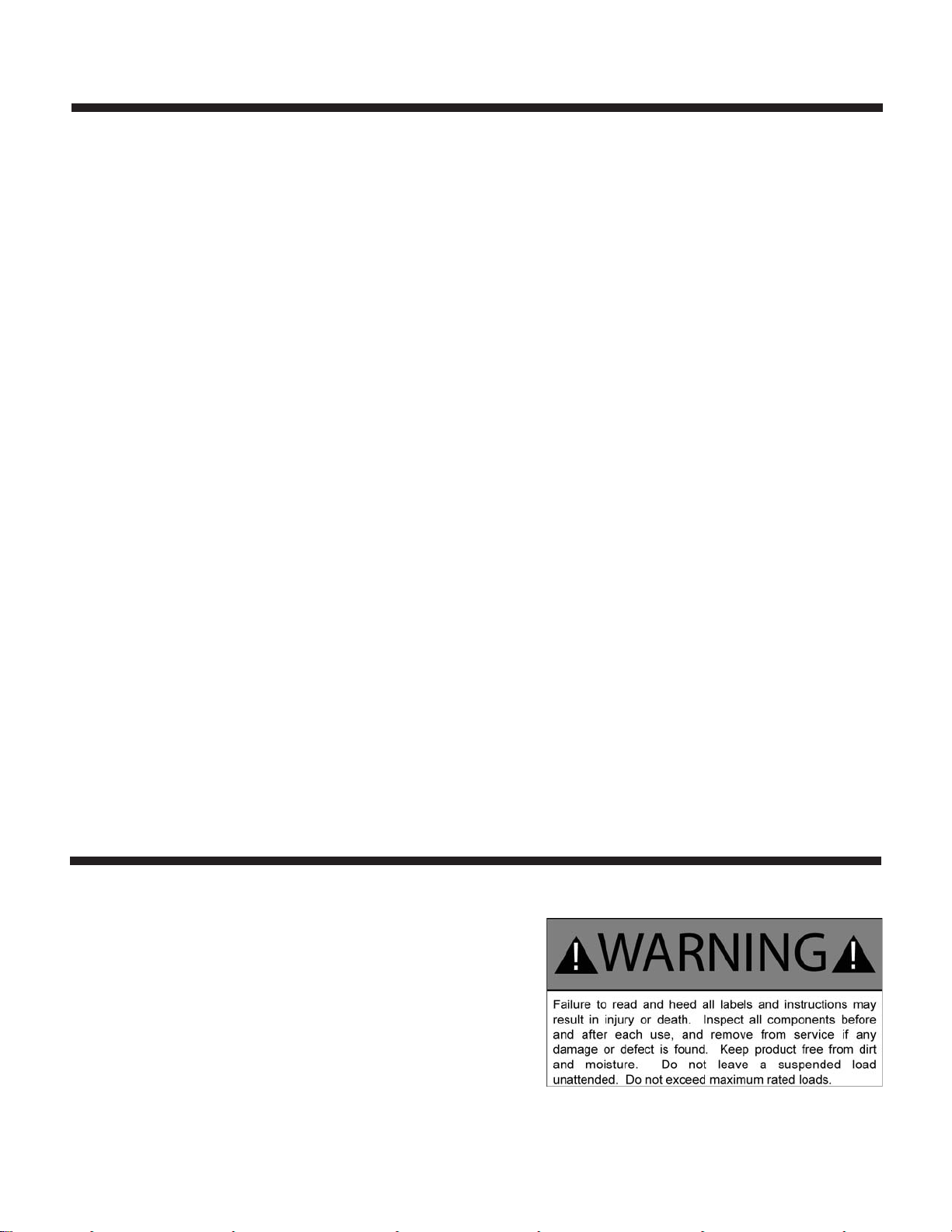
4.1 - Warning Statement
WARNING!
Products manufactured or sold by the T.A. Pelsue Company are
intended for use by professionals trained and experienced in the
use, inspection and maintenance of these products.
Paraprofessional users such as volunteer rescue workers and
sportsmen involved in risk sports such as climbing and caving will
be held to the same standard of experience and training as profes-
sionals.
Technical rescue, repelling, climbing and the training involved are
hazardous activities. Each situation has its own unique conditions
and must be evaluated. Effective risk management comes from
experience, proper training and good personal judgement.

#501003-001 - Product Manual: Model #TFAT-14C TELESCOPING FALL ARREST TOWER - Revision 00 - Date: 06-16-2008 Page 11
SAFETY ALERT SYMBOL
This Safety Alert symbol means ATTENTION! BECOME
ALERT! YOUR SAFETY IS INVOLVED!
TheSafetyAlert symbol identifiesimportant safety messages
on your Pelsue Retrieval Product and in the manual. When
you see this symbol, be alert to the possibility of personal
injury or death. Follow the instruction in the safety mes-
sage.
Why is this symbol important to you?
3 BIG Reasons: Accidents Disable and Kill.
Accidents Cost You Money.
Accidents Can Be Avoided.
4.2 - SafetyAlert Symbol
4.3 - General Safety Information
1. Read, understand, and follow the Product Manual and all safety signs before using, maintaining or inspecting the
equipment.
2. Refer to and follow applicable standards and regulations. Comply with requirements of local regulations for your
applications.
3. Establish an equipment-use training program for inexperienced employees. Only trained, competent persons shall
use the equipment. An untrained operator is not qualified to operate the system.
4. Have a first-aid kit available for use should the need arise and know how to use it.
5. Provide a fire extinguisher for use in case of an accident. Store in a highly visible place.
6. Install and properly secure all guards and shields before operating.
7. Wear appropriate protective gear. This list includes but is not limited to:
• A hard hat
• Protective shoes with slip resistant soles
• Heavy gloves
• Protective clothing
• Face Protection
8. Review and follow the Pre-Operation Checklist before using a component in the system or system itself.
9. Establish a regular maintenance and inspection program with your equipment and maintain detailed records.
10.Review safety related items and operating instructions with all personnel on a regular basis.
4.4 - Operating Safety
1. Read, understand and follow the Product Manual as well as all printed warnings that may be located on the product itself
before using, maintaining or inspecting the equipment.
2. Train all operators before allowing them to use the product.An untrained operator exposes themselves, bystanders
and workers to possible serious injury or death.
3. Visuallyinspect the productandallauxiliarycomponentsandequipment before using. Correct any problems before
using the equipment.
4. Securely anchor the product before using.
5. Use only certified anchor and connector components in your system.
6. Use only an approved full body harness for the workers.

#501003-001 - Product Manual: Model #TFAT-14C TELESCOPING FALL ARREST TOWER - Revision 00 - Date: 06-16-2008
Page 12
4.4 - Operating Safety (continued)
4.5 - Maintenance Safety
1. Read, understand and follow the Product Manual as well as any printed warnings that may be present on the product
before using, maintaining or inspecting the equipment.
2. ANSI and OSHA require a regular inspection program for all fall arrest equipment as well as properly-documented
results of the inspections. Follow the inspection procedures contained in this manual and use the inspection form
to document the results (see section 6.0).
3. Keep instructional and safety signs clean and legible at all times. Clean or replace as required.
4. Removetheequipmentfromserviceifa problem is found during the inspection. Return to an authorized repair depot
or the factory for service.
The Pelsue Model #TFAT-14C Telescopic Fall Arrest Tower is designed to provide a single elevated fall arrest system
anchor point. Every new operator must read, understand and follow the instructions in this Product Manual. No person
shouldbe permitted to use the equipment without prior propertraining.The training should be reviewed withexperienced
operators on a regular basis. At regular intervals, perform a detailed inspection of the equipment and document the
results. Remove the product from service if any deficiencies are found.Alterations or misuse of this equipment or failure
to follow instructions may result in serious injury or death.
It is the responsibility of the owner’s organization to ensure that the proper training is provided to all operators of any fall
arrest device before they start working with the equipment. Follow all safety instructions exactly. Safety is everyone’s
business. By following recommended procedures, a safe working environment is provided for the operator, bystanders
and the area around the work site. Untrained operators are not qualified to operate the equipment.
Manyfeatures incorporatedinto this equipmentare theresultof suggestionsmadeby customerslikeyou. Readthis manual
carefully to learn how to operate & install the equipment safely and as intended. By following the operating instructions
in conjunction with a good maintenance program, your product will provide many years of trouble free service.
4.6 - New Operator or Owner
7. Always work in teams. When working upon an elevated surface where a fall is possible, making a subsequent
rescue necessary, personnel must be available and ready for rescue immediately. Working alone with this equip-
ment is inherently dangerous and not advised!
8. Do not exceed the capacity & capabilities of the system at any time (see section 5.1).
9. Establish a regular training program for all operators and potential rescuers.
10. Establish a detailed inspection program for your equipment and document the findings. Return the equipment to
the manufacturer for repair if any problems are found.
11. Plan your work program before starting. Have the required people, equipment and procedures readily available in
order to safely complete any task prior to commencing.
12. Do not use the equipment around physical or environmental hazards. This list includes but is not limited to:
• Corrosion that may affect the structural integrity of the lifeline or other components.
• Chemicals which can degrade components in a manner which can not be visually identified.
• Toxic gases: Rescuers or workers can be killed in toxic environments.
• Heat or elevated temperatures.
• Moving machinery: Workers or auxiliary equipment can be contacted by or pulled into moving components.
• Sharp edges: Workers or the rescue equipment can be injured by or damaged by sharp edges or components.
• Electrical hazards: Stay away from power lines or components carrying electrical power.
• Overload: Do not overload the system at any time during operation (see section 5.1).
• Follow elevated work area and fall protection regulations and standards.

#501003-001 - Product Manual: Model #TFAT-14C TELESCOPING FALL ARREST TOWER - Revision 00 - Date: 06-16-2008 Page 13
The load rating
given here super-
sedes any load
rating reported
with the composite
tower insert. The
capabilities of the
#500573-001 tower
are limited by the
#TFAT-14C tele-
scoping system.
5.0 - Product Operation
The Pelsue #TFAT-14C Telescopic FallArrest Tower is constructed of structural aluminum and incorporates several steel
and engineered plastic components. The #TFAT-14C Telescopic tower is designed as an accessory component to the
Pelsue Model #FT-C70 Fall Arrest Tower. The Model #FT-C70 possesses a composite upper section (#500573-001)
which can be inserted into its standard base (#500019-001) to create a 70” high anchor point or can be inserted into the
#TFAT-14C to create up to a 14’ high anchor point. All specifications, instructions, and procedures provided within this
manual or upon Pelsue Specification Documents are based upon and only valid for usage with a Pelsue #500573-001
Composite TowerAssembly. The T.A. Pelsue Company can not verify equipment safety and/or compliance when utilized
with anything other than Pelsue approved bases and accessories.
5.1 - Product Description & Capabilities
The following section will address the capabilities and the general operation of the Pelsue #TFAT-14C Telescopic Fall
Arrest Tower. The instructions contained within this section should be adhered to each and every time the product is
used. Any person tasked with installing or operating this piece of equipment should be familiar with these procedures.
! WARNING ! - The user must ensure that the structure to which the tower base is installed is
capable of withstanding the weight of the system combined with the system proof loads in order to
retain the stated compliance of the entire system.
! WARNING ! - The user must ensure that the tower system is properly installed & completely
vertical in order to retain the stated compliance and stability of the entire system.
! WARNING ! - The user must ensure that the handles of the tower are set in one of the three provided positions
and that the pin securing the composite section is locked in place in order to retain the stated compliance of the entire
system.
Figure #5.1a: Loading Diagram
#TFAT-14C with #500573-001
1800 LB.
[816.5 kg]
Proof Load
20º
#500573-001
TFAT-14C
**The Model #TFAT-14C can only be used in conjunction with part #500573-001
Composite FallArrest Tower and is not rated for usage on its own, or with any
other upper insert.
The #500573-001 composite tower is available separately from Pelsue, or can
be ordered as part of a complete fall arrest tower system, including a standard
base as a Pelsue Model #FT-C70.
Telescopic Fall Arrest Tower - #TFAT-14C
General Specifications
• Safe Working Radius @ Tower Base- 5’
• Structure Weight - 75 lbs.
• 3 Tower Heights - Maximum Height - 13’ 9”
Mid Height - 11’ 9”
Minimum Height - 10’ 4”
Load Capacity
• Single user with a maximum weight of 350 lb.
with a safe working radius of 5’ @ Tower Base
• Refer to loading diagrams for proof loads.
Materials & Construction
• Welded Aluminum
Features:
• Easily installs adjacent to elevated work stations
requiring access.
• Provides an elevated fall arrest anchor point
• Constructed primarily of lightweight &
corrosion-resistant powder coated
aluminum
! WARNING !- Any lifeline connection made to the #TFAT-14C system must be made in conjunction with
a 900 LB. MAF fall arrest device. Failure to do so can result in serious injury or even death.

#501003-001 - Product Manual: Model #TFAT-14C TELESCOPING FALL ARREST TOWER - Revision 00 - Date: 06-16-2008
Page 14
Prior to Operation, the #TFAT-14C Telescopic Fall Arrest Tower must be
configured and prepared according to the following guidelines.
1. Pre-Operation Inspection:
It is necessary to perform a visual inspection prior to each time using the
product. If deficiencies are found, remove the product from service and
contact the T.A. Pelsue. regarding repair. The following checklist coupled
with Figure #5.2a should be used as a guide to determine whether the
equipment is in good operating condition prior to usage. Equipment that
is not in good condition can endanger the safety of the user and nearby
workers.
The Pre-Operation Visual Inspection is not limited to, but must include the
following items;
a. Checkthat the product has no structural defects, suchasdents,bends,
cracks, or fractures.
b. Ensure that all product rating & warning labels are clear and legible.
c. Checkthat the sections slide smoothly inandout of each other (Binding
can be indicative of other damage).
d. All hardware (Pins, Leveling Screws) have not been damaged
and are in working condition.
5.1 - Product Description & Capabilities (continued)
5.2 - Product Installation & Set-up
Figure #5.2a: #TFAT-14C Series
Pre-Operation Inspection Points
Leveling
Screws
Pin
Base Plate
Maximum Height
Loading Diagram
310 LB.
[140.6 kg]
Maximum
User Weight
20º
5’ SAFE
WORKING
RADIUS
(All Heights)
Additional Requirements & Notes:
• The #TFAT-14C Series Fall Arrest Tower must be set on a level surface and
made vertical prior to use.
• In order to ensure compliance, it is the user’s responsibility to ensure that
the structure to which the #TFAT-14C is attached is capable of withstand-
ing all of the loads imparted to it by the proof-loaded #TFAT-14C Fall Arrest
Tower.
• An approved Pelsue base assembly is required for operation & installation
(i.e. Pelsue Model #FB-SW1 Base Plate).
• Any single user lifeline connection made to the Model #TFAT-14C tower
system must be made utilizing a 900 LB. MAF (Maximum Arrest Force)
device integrated into the lifeline.
! WARNING ! - Any lifeline connection made to the
#TFAT-14C system must be made in conjunction with a
900 LB. MAF fall arrest device. Failure to do so can result
in serious injury or even death.
! WARNING ! - A pre-operation inspection is required each time
the product is to be installed or utilized as a connection point.

#501003-001 - Product Manual: Model #TFAT-14C TELESCOPING FALL ARREST TOWER - Revision 00 - Date: 06-16-2008 Page 15
Leveling
Pegs
2. Setup of the #TFAT-14C Telescopic Fall Arrest
Tower:
Choose a location where installation will provide suitable
proximity to the work area yet minimize obstructions during
use and in the event a rescue is necessary. Once a location
is chosen;
a. Alignthe holesin the towerbase with theholes ofthebase
plate “ears” and insert the base’s pin in order to secure
the tower to the base plate (Refer to Fig. #5.2b).
b. Plumb the #TFAT-14C using the levelling pegs (Refer to
Fig. #5.2c) so that the structure is vertical and perpen-
dicular to the intended working surface.
5.2 - Product Installation & Set-up (continued)
Figure #5.2c: #TFAT-14C
Tower Vertical and Secured to Structure
Figure #5.2b: #TFAT-14C
Base Pin
! WARNING ! - The Model #TFAT-14C must be
plumbed vertically prior to the attachment of any
lifeline. The #TFAT-14C is only approved for life-
line attachment when mounted vertically
! WARNING ! - Ensure that the
mounting structure will withstand
all loads imparted to it by the proof-
loaded #TFAT-14C tower system
! WARNING ! The Model #TFAT-14C must
be positioned so that the lifeline angle will
not exceed 20 degrees off of the vertical in
the event that a fall occurs.

#501003-001 - Product Manual: Model #TFAT-14C TELESCOPING FALL ARREST TOWER - Revision 00 - Date: 06-16-2008
Page 16
5.2 - Product Installation & Set-up (continued)
c. Lower Position: If the #TFAT-14C is to be utilized in its lowest position,
remove the “T” Handle hitch pin at the upper end of the tower, insert the
Composite tower section into the #TFAT-14C** and reinsert the “T” handle
pinthereby securing the compositetubeto the #TFAT-14C. The composite
tube may need to be rotated by hand in order to align the pin holes.
Middle & Upper Position: If the #TFAT-14C is to be utilized in either of
its middle or upper position, remove the “T” Handle hitch pin at the upper
end of the tower and insert the Composite tower section into the top the
#TFAT-14C**. Prior to securing, grasp the two protruding handles, one in
each hand, and raise the tower to its middle position. The middle section
must be rotated approximately 10 degrees in order to secure the handle
shaftinto the inverted “J-shaped” slot. Re-Insert the “T”Handlepinthereby
securing the composite tube to the #TFAT-14C. The composite tube may
need to be rotated by hand in order to align the pin holes. Once the pin si
inserted,the tower can be extended and securedinits upper most position,
using the two handles, if maximum height is required.
d. Asinglelifelinemay now be attached toanyof the three tie-offrings located
at the top of the composite tower. Only a single lifeline may be attached
to the top of the tower at any one. Any attached lifeline must be equipped
with a 900 LB. MAF (Maximum Arrest Force) Fall Arrest Device.
**NOTE: It will likely be easier to attach the lifeline/SRL to the composite
towers anchorage point prior to inserting into to #TFAT-14C or elevating the
system to its desired position.
Figure #5.2d: Composite
Component Tower Installation
Height
Adjustment
Handles(2X)
Composite
Tower
“T” Handle
Tower
Anchoring
Pin
! DANGER !
The 3-Person rating published on
the composite tower is not valid
when installed within the #TFAT-
14C system. The 3-Person rating
requires Installation within the
#500019-001Uni-Lite BaseAssem-
bly.

#501003-001 - Product Manual: Model #TFAT-14C TELESCOPING FALL ARREST TOWER - Revision 00 - Date: 06-16-2008 Page 17
! WARNING ! The single
allowed lifeline connection
must be made in conjunction
with a 900 LB. MAF (Maxi-
mum Arrest Force) Fall Arrest
Device
! DANGER !
The 3-Person rating published
on the composite tower is not
valid when installed within
the #TFAT-14C system. The
3-Person rating requires Instal-
lation within the #500019-001
Uni-Lite Base Assembly.
Figure #5.2e: #TFAT-14C
Installed & secured at Mid-Position
5.2 - Product Installation & Set-up (continued)
Detail “C”: Anchorage
Tie-Off Rings
Detail “B”: Properly
Secured “T” Handle
Tower Anchoring Pin
Detail “A”: Handle
Shaft Properly Secured
in the inverted “J” Slot at
the Mid Position
! WARNING ! The model #TFAT-
14C is only approved for the attach-
ment of a single lifeline for a user of
a maximum of 310 LBS.
! WARNING ! The Handle
Shaft must be secured in one
of the 3X) Inverted “J” slots
as shown in Detail “A” prior to
usage of the system

#501003-001 - Product Manual: Model #TFAT-14C TELESCOPING FALL ARREST TOWER - Revision 00 - Date: 06-16-2008
Page 18
In general, the Model #TFAT-14C is intended to be a maintenance-free piece of equipment, however several steps can
be taken to keep the system in top-notch working order and also extend the working life of the product.
Before Each Use:
1. Visual Inspection: Perform a complete visual inspection. Refer to section 6.2 for guidelines and take any
maintenance steps that are necessary.
Annually:
1. Clean Product: Use a damp cloth and mild soap to clean the structure and labels of dirt and residue. Be sure
that the labels are legible (replacements are available from Pelsue)
2. Lubricate the threaded screw pegs in order to ensure smooth operation.
3. Complete Inspection: Perform a thorough inspection, paying attention to the bullet points provided within
section6.2.Recordtheresultsandfilethedocumentationforfuturereference. Alog sheet has been provided
in section 6.3 specifically for the recording of the dates & results of the annual system inspections.
Periodic Factory Service Inspection: It is recommended that the product be serviced by a factory authorized
service center or the manufacturer after a period of three years. Extreme working conditions may indicate
the necessity to increase the frequency. Factory servicing shall include but not be limited to an intensive
inspectionand cleaning of all internal and external components. Failure toprovideproperservice may shorten
product life and could endanger performance or function.
6.2 - Inspection
MAINTENANCE & INSPECTION
6.0 - Maintenance & Inspection
1. Read, understand and follow the Product Manual and all
informationlocated on theproduct beforeusing, maintain-
ing or inspecting the equipment.
2. ANSIand OSHArequirea regularinspectionprogramfor all
fall arrest equipment and to maintain documented results
of these inspections. Follow the inspection procedure
contained in this manual and use the inspection form to
document the results.
3. Keep instructional and safety signs clean and legible at
all times. Clean or replace as required.
4. Remove the equipment from service if a problem is found
duringthe inspection.Return toan authorizedrepair depot
or the factory for service.
6.1 - Maintenance
When completing an inspection of the Model #TFAT-14C Telescopic FallArrest Tower, the following specific items should
be checked;
1. Labels:
Check that all of the labels are clean and legible (Refer to Section 3.1). Clean the labels if any are dirty using mild
soap and a damp cloth. Replace them if any are illegible. Decals & labels provide valuable warning and caution
information applicable to product usage and limitations, and should be visible and present at all times.
2. Fasteners:
Check that all screws and other fasteners are present and secure. Note that not all fasteners are tightened to their
maximum allowable torque. This is done in order to allow for pivoting and folding motions in certain components.
Over-tightening of fasteners can interfere with the operation of the device and can damage the structure. Consult
the Pelsue Company with any questions regarding fastener torque or specifications. All fasteners on the Model
#TFAT-14C system are of a self-locking design. Bolt threads should extend all the way though their locking nuts. If

#501003-001 - Product Manual: Model #TFAT-14C TELESCOPING FALL ARREST TOWER - Revision 00 - Date: 06-16-2008 Page 19
6.2 - Inspection (continued)
any fasteners have appeared to “back-out” or loosen the product should be removed from service until the problem
can be identified and corrected.
3. Leveling Pegs:
Ensure that the Leveling Screws are in working condition. Oil or grease the threaded portions if required, and at
least annually. Also, visually inspect and verify that both the internal and external threads of the leveling screw
system do not contain an inordinate amount of debris or metal shavings and have not been otherwise damaged.
4. Structure:
The entire product structure should be checked for cracks, dents, bends or breaks. If there are major dents or any
other structural damage, the unit should be removed from service and returned to the factory for evaluation and
possiblerepair. If there is any question astothestructuralintegrity of the product, remove form service immediately
and await further evaluation by a qualified organization or individual.
• Pay attention to the bearing collars in the middle section. Ensure that they are present within the tower receiver
and that they are damage free.
• Pay special attention to weld locations: look for cracks or separation at the welds. Keep in mind that the powder
coating can age and crack, this normal paint cracking can be confused with structural cracking. If there is any
uncertainty with regards to cracks, contact the Pelsue service department for assistance and/or recommenda-
tions
• Ensure that the two sections of the tower can move freely within one another when stood vertically and not sup-
porting a load.

#501003-001 - Product Manual: Model #TFAT-14C TELESCOPING FALL ARREST TOWER - Revision 00 - Date: 06-16-2008
Page 20
6.3 - Inspection Log
Date Labels Pins & Fasteners Leveling Screws Overall Structure Notes
Inspector (print & sign) :
Place a check (¥)in the box if item is acceptable, place an x (X) in the box if item requires maintenance or repair
Model Number
:
Serial Number
:
Date Purchased
:
#TFAT-14C
Table of contents
Other Pelsue Safety Equipment manuals